Démontage :
1 : Déposer le cache (1) avec un tournevis.
2 : Dévisser la vis (2).
3 : Insérer et tourner la clé (3) de 45°dans le sens anti-
horaire, puis déposer le mécanisme (4).
4 : Tourner la plaque de verrouillage (5) dans le sens
“Open”, puis la déposer.
5 : Extraire le contact électrique (6).
6 : Dévisser les vis (7) et extraire le boîtier (8).
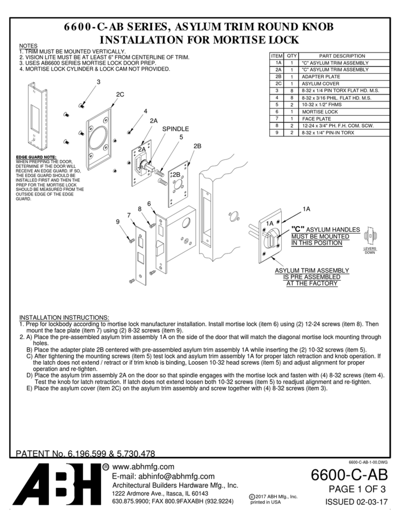
Mise en place de l’inverseur :
(pour un montage encastré, commencer à l’étape 2)
1 : Fixer le boîtier applique sur le mur par les quatre trous
oblong Ø5. Attention au sens de montage (fig.2 ).
2 : Mettre en place le boîtier (8) et visser les vis (7).
Attention au sens de montage (fig.1).
3 : Mettre en place le contact électrique (6).
4 : Mettre en place la plaque de verrouillage (5), puis la
tourner dans le sens “Close”.
5 : Mettre en place le mécanisme (4) avec la clé orientée
de 45° dans le sens anti-horaire par rapport à la posi-
tion verticale.
6 : Visser la vis (2) et mettre en place le cache (A) pour
une utilisation avec coffret d’automatisme ou le cache
(B) pour une utilisation stable - instable - mixte.
INVERSEUR UNIVERSEL À CLEF
F
SOMFY SAS, 400 Avenue de la République, 74300 CLUSES - FRANCE - &(33) 4 50 96 70 00 - capital 20.000.000 €- RCS Bonneville 303.970.230
Lire attentivement cette notice
avant toute utilisation.
5010776A
1Montage / Démontage
3Commande directe d’un moteur
2Configuration des modes de fonctionnements INSTABLE / STABLE / MIXTE
sens sens
Fonctionnement mixte
Stable sens
Instable sens
==
R
T
R
T
R
T
Fonctionnement
Instable sens et sens
R
T
R
T
Fonctionnement
Stable sens et sens
R
T
R
T
En Europe, le mode de fonctionnement doit être en conformité avec la Norme EN13241-1
Bleu
Marron
Noir
Rouge
Jaune/vert
230V - 50Hz
- Verrouillage mécanique du couvercle obligeant d’introduire la clé et de
tourner le barillet pour accéder aux câblages.
- Indice de protection IP : 54
- Conducteurs de section 1,5 mm2 maximum
- Contact : 5A - 230V AC
- Boitier applique pré découpé pour un presse étoupe de ø16 (non fourni)
- 4 Perçages oblong ø5 pour fixation du boîtier applique
- Livré avec 3 clés identiques (Barillet Européen)
- 2 Montages possibles : Applique et Encastré
- 4 possibilités de commande : STABLE - INSTABLE - MIXTE - BOUTON POUSSOIR
5Caractéristiques techniques
4Commande d’un coffret d’automatisme
Pour inverser le sens de rotation du moteur, inverser les fils (2) et (3) du moteur. Pour des raisons de sécurité ne pas laisser de câbles apparents.
L’inverseur universel à clef est livré en mode de fonctionnement instable. Pour changer le mode de fonctionnement, agir sur les cavaliers jaunes comme indiqué ci-dessous.
Boîte de dérivation
(non fourni)
Câblage à réaliser en conformité avec la norme CEI 364
Pour cette utilisation, les cavaliers doivent être positionnés pour un fonctionnement instable dans les deux sens (voir chapitre 2).
LT80 / LT 90
(fig.1)(fig.2)
(A)
(B)
L’inverseur à clef universel est conforme à la norme EN60947.
L’installation associée doit être conforme à la norme EN13241-1.
