8
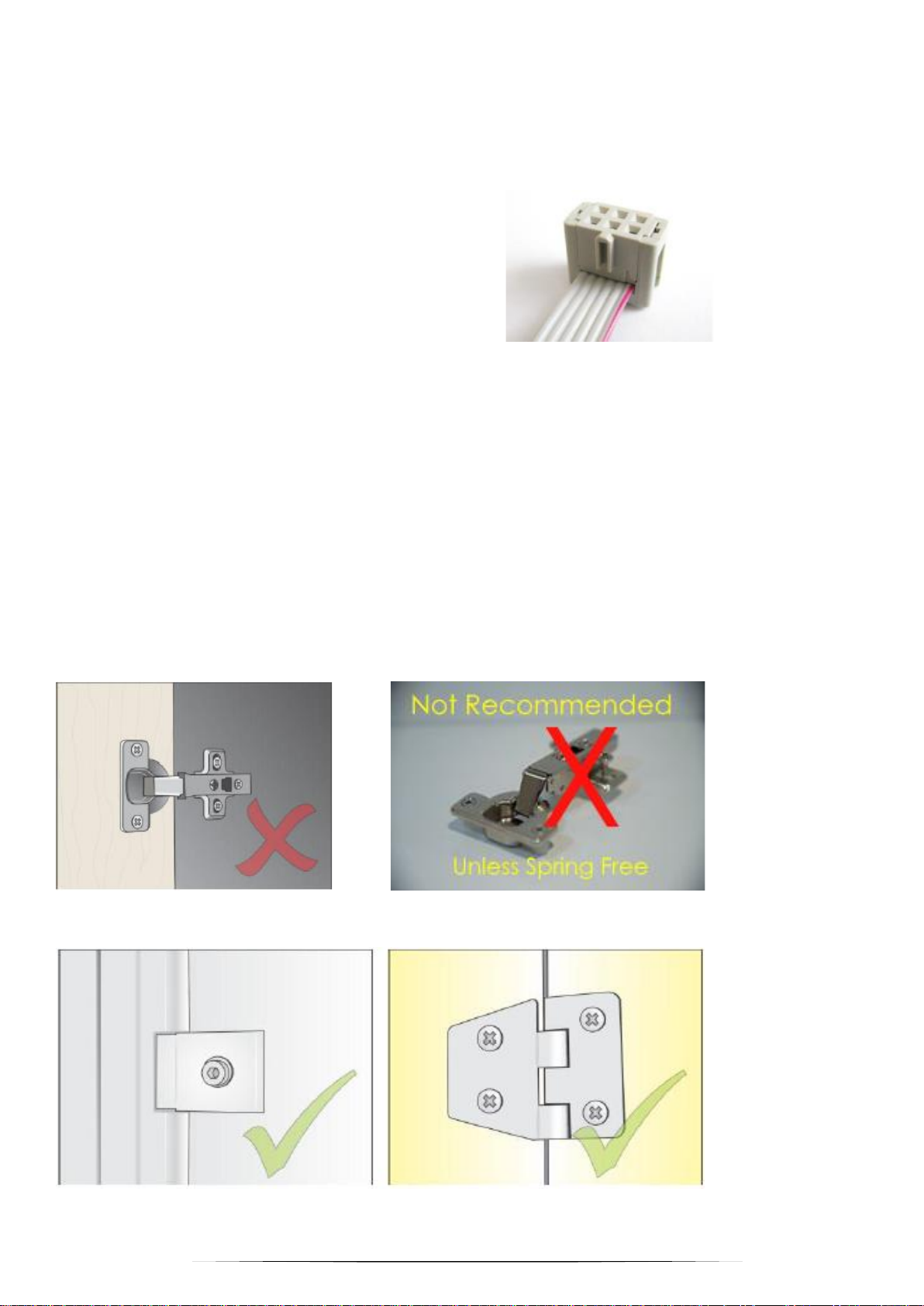
•Next, the Lock Body should be mounted first and then the door strike.
•There is a single type of Lock Body and it can be used for both Left and Right opening locker doors.
•(The lock is simply flipped over, as the mounting holes allow this)
•The Lock Body is usually placed on the side of the locker, or for very narrow lockers the Lock Body can be placed at
either the top or bottom of the locker.
•Use the following mounting screw information, to attach the Lock Body to the locker cabinet wall and mounting the
strike to the locker door.
•(For HPL or similar materials, it is best to tap 4mm threads or use threaded inserts, to mount the Lock Body and
Strike)
Mounting Screws
Use Pan Head screws only.
No Countersunk screws are to be used.
Damage to the lock can occur and this is not covered under warranty, if the wrong type of screws are used.
Stainless Steel PH2 screws are recommended for harsh environments or Zinc plated for office areas.
•32 mm 6g for Front of lock (x2)
•25mm 6g for Rear of lock (x2)
•16mm 6g for Strike –Mounted to locker door (x2)
•4mm Washers for Strike screws (x2)
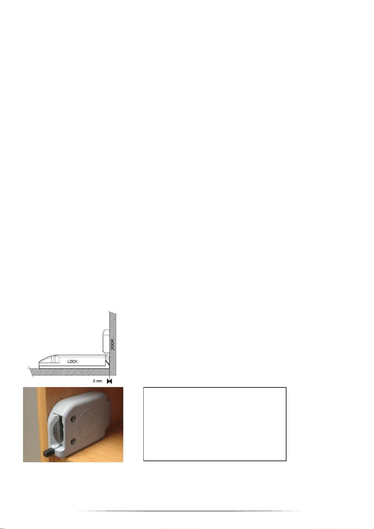
Mounting the Electronic Lock Body. –Continued.
13. The Electronic Lock body should be mounted so that the front face of the lock is slightly proud or flush with the
front face of the Locker carcass. If rubber bumpers are used, the Lock body must be moved further out.
The Electronic Lock body MUST NOT BE BEHIND THE FRONT FACE OF THE LOCKER CARCASS.