SOMFY Levixo 40 24V RTS User manual

Levixo 40/60 24V RTS
Manuel d'installation
Installation instructions
Montaj kılavuzu
FR
EN
TR
FA
AR
FR LEVIXO 40/60 24V RTS
2 Copyright©2017 SOMFY ACTIVITES SA. All rights reserved.
DANGER
Lamotorisationdoitêtreinstalléeetrégléeparuninstallateur
professionnel de la motorisation et de l’automatisation de
l’habitat, conformément à la réglementation du pays dans
lequel elle est mise en service.
Le non respect de ces instructions pourrait gravement
blesser des personnes, par exemple écrasées par la barrière.
1.1.Mise en garde - Instructions importantes de
sécurité
AVERTISSEMENT
Il est important pour la sécurité des personnes de suivre
toutes les instructions car une installation incorrecte peut
entraîner des blessures graves. Conserver ces instructions.
L’installateur doit impérativement former tous les
utilisateurs pour garantir une utilisation en toute sécurité de
la motorisation.
Le manuel doit être remis à l’utilisateur final. L’installateur
doit explicitement expliquer à l’utilisateur final que
l’installation, le réglage et la maintenance de la motorisation
doivent être réalisés par un professionnel de la motorisation
et de l’automatisation de l’habitat.
1.2.Introduction
1.2.1.Informations importantes
Ce produit est une barrière exclusivement réservée au passage
de véhicules motorisés. Ces instructions ont notamment pour
objectif de satisfaire les exigences de la dite norme et ainsi
d’assurer la sécurité des biens et des personnes.
AVERTISSEMENT
La barrière doit être exclusivement réservée au
passage des véhicules. Le passage des piétons est
strictement interdit dans l’aire de manoeuvre de la
barrière. Il est nécessaire de prévoir un passage piéton
distinct.
AVERTISSEMENT
Toute utilisation de ce produit hors du domaine d’application
décrit dans cette notice est interdite (voir paragraphe
«Domaine d’application» du manuel d’installation).
VERSION ORIGINALE DU MANUEL
SOMMAIRE
GÉNÉRALITÉS
Consignes de sécurité
Danger
Signale un danger entraînant immédiatement la mort ou des blessures graves.
Avertissement
Signale un danger susceptible d’entraîner la mort ou des blessures graves.
Précaution
Signale un danger susceptible d’entraîner des blessures légères ou moyennement graves.
Attention
Signale un danger susceptible d’endommager ou de détruire le produit.
1.CONSIGNES DE SÉCURITÉ
1. Consignes de sécurité 2
1.1. Mise en garde - Instructions importantes de sécurité 2
1.2. Introduction 2
1.3. Vérifications préliminaires 3
1.4. Installation électrique 3
1.5. Précautions de manutention 3
1.6. Précautions vestimentaires 3
1.7. Consignes de sécurité relatives à l’installation 3
1.8. Consignes de sécurité relatives à l’utilisation 3
1.9. Consignes de sécurité relatives à la maintenance 3
1.10.Réglementation 4
1.11.Assistance 4
2. Description du produit 4
2.1. Domaine d’application 4
2.2. Encombrement - Fig. 1 4
2.3. Installation type - Fig. 2 4
3. Installation 4
3.1. Préparation des fondations 4
3.2. Fixation du caisson - Fig. 5 4
3.3. Montage de la lisse - Fig. 6 4
3.4. Réglage des fins de course 5
3.5. Installation et réglage du ressort - Fig. 8 5
3.6. Equilibrage de la lisse - Fig. 9 5
3.7. Raccordement électrique - Fig. 10 5
4. Mise en service 5
4.1. Navigation dans le menu des paramètres 5
4.2. Réglage du sens d'ouverture de la barrière - Fig. 11 5
4.3. Calibrage des fins de course électronique - Fig.12 5
4.4. Mémorisation des télécommandes - Fig. 13 5
4.5. A vérifier avant toute utilisation 6
5. Utilisation 6
5.1. Utilisation standard des télécommandes - Fig. 14 6
5.2. Verrouillage/déverrouillage de la lisse - Fig. 15 6
5.3. Fonctionnement de la détection d’obstacle 6
5.4. Formation des utilisateurs 6
6. Raccordement des périphériques 6
6.1. Plan de câblage général - Fig. 16 6
6.2. Description des différents périphériques 6
7. Paramétrage avancé 6
7.1. Navigation en mode paramétrage 6
7.2. Liste des paramètres (menus et sous-menus) 7
8. Effacement des télécommandes et de tous les réglages 9
8.1. Effacement des réglages - Fig. 22 9
8.2. Effacement des télécommandes mémorisées - Fig.23 9
9. Diagnostic et dépannages 9
9.1. Diagnostic 9
10. Caractéristiques techniques 9
LEVIXO 40/60 24V RTS FR
3Copyright©2017 SOMFY ACTIVITES SA. All rights reserved.
L’utilisation de tout accessoire ou de tout composant non
préconisé par Somfy est interdit - la sécurité des personnes
ne serait pas assurée.
Tout irrespect des instructions figurant dans cette notice exclut
toute responsabilité et garantie de Somfy.
Si un doute apparaît lors de l’installation de la motorisation ou
pour obtenir des informations complémentaires, consulter le site
internet www.somfy.com.
Ces instructions sont susceptibles d’être modifiées en cas
d’évolution des normes ou de la motorisation.
1.3.Vérifications préliminaires
1.3.1.Environnement d’installation
ATTENTION
Ne pas projeter d’eau sur la motorisation.
Ne pas installer la motorisation dans un milieu explosif.
Vérifier que la plage de température marquée sur la
motorisation est adaptée à l’emplacement.
DANGER
MISE EN GARDE : Toute intervention sur les ressorts de la
barrière peut représenter un danger.
1.3.2.Spécifications de la barrière à motoriser
Après installation, s’assurer que les parties de la barrière
n’empiètent pas sur les trottoirs ou sur la voie publique.
1.4.Installation électrique
DANGER
L’installation de l’alimentation électrique doit être conforme
aux normes en vigueur dans le pays où est installée la
motorisation et doit être faite par un personnel qualifié.
La ligne électrique doit être exclusivement réservée à la
motorisation et dotée d’une protection constituée :
• d’un fusible ou disjoncteur calibre 10A,
• et d’un dispositif de type différentiel (30mA).
Un moyen de déconnexion omnipolaire de l’alimentation
doit être prévu. Les interrupteurs prévus pour assurer
une coupure omnipolaire des appareils fixes doivent être
raccordés directement aux bornes d'alimentation et doivent
avoir une distance de séparation des contacts sur tous les
pôles pour assurer une déconnexion complète dans les
conditions de catégorie de surtension III.
Les câbles basse tension soumis aux intempéries doivent
être au minimum de type H07RN-F.
L’installation d’un parafoudre est conseillée (de tension
résiduelle d’un maximum de 2kV).
Passage des câbles
Les câbles enterrés doivent être équipés d’une gaine de protection
de diamètre suffisant pour passer le câble du moteur et les câbles
des accessoires.
Pour les câbles non enterrés, utiliser un passe-câble qui
supportera le passage des véhicules (réf. 2400484).
1.5.Précautions de manutention
Utiliser les moyens de manutention adaptés (forme,
encombrement et poids de la charge) par exemple un diable de
transport.
1.6.Précautions vestimentaires
Enlever tous bijoux (bracelet, chaîne ou autres) lors de
l’installation.
Pour les opérations de manipulation, de perçage et de soudure,
porter les protections adéquates (lunettes spéciales, gants,
casque antibruit, etc.).
1.7.Consignes de sécurité relatives à l’installation
DANGER
Ne pas raccorder la motorisation à une source d’alimentation
(secteur) avant d’avoir terminé l’installation.
AVERTISSEMENT
S’assurer que les zones dangereuses (écrasement,
cisaillement, coincement) entre la partie entraînée et les
parties fixes environnantes dues au mouvement d’ouverture
de la partie entraînée sont évitées ou signalées sur
l’installation.
AVERTISSEMENT
Il est strictement interdit de modifier l’un des éléments
fournis dans ce kit ou d’utiliser un élément additif non
préconisé dans ce manuel.
Surveiller la barrière en mouvement et maintenir les personnes
éloignées.
Ne pas utiliser d’adhésifs pour fixer la motorisation.
AVERTISSEMENT
Le déverrouillage manuel peut entraîner un mouvement
incontrôlé de la barrière.
Après installation, s’assurer que :
• le mécanisme est correctement réglé
• le dispositif de débrayage manuel fonctionne correctement
AVERTISSEMENT
Dans le cas d’un fonctionnement en mode automatique ou
d’une commande hors vue, il est impératif d’installer des
cellules photoélectriques.
La motorisation en mode automatique est celle qui
fonctionne au moins dans une direction sans activation
intentionnelle de l'utilisateur.
Dans le cas d’un fonctionnement en mode automatique ou si la
barrière donne sur la voie publique, l’installation d’un feu orange
peut être exigée, conformément à la réglementation du pays
dans lequel la motorisation est mise en service.
1.8.Consignes de sécurité relatives à l’utilisation
AVERTISSEMENT
Cette motorisation peut être utilisée par des enfants âgés
d’au moins 8 ans et par des personnes ayant des capacités
physiques, sensorielles ou mentales réduites ou dénuées
d’expérience ou de connaissance, s’ils (si elles) sont
correctement surveillé(e)s ou si des instructions relatives à
l’utilisation de la motorisation en toute sécurité leur ont été
données et si les risques encourus ont été appréhendés.
Ne pas laisser les enfants jouer avec la motorisation.
Ne pas laisser les enfants jouer avec les dispositifs de
commande de la barrière. Mettre les télécommandes hors
de portée des enfants.
Le nettoyage et l’entretien par l’usager ne doivent pas être
effectués par des enfants.
1.9.Consignesde sécuritérelatives àlamaintenance
DANGER
La motorisation doit être déconnectée de toute source
d’alimentation durant le nettoyage, la maintenance et lors
du remplacement des pièces.

FR LEVIXO 40/60 24V RTS
4 Copyright©2017 SOMFY ACTIVITES SA. All rights reserved.
1.10. Réglementation
Somfy déclare que le produit décrit dans ces instructions lorsqu’il
est utilisé conformément à ces instructions, est conforme aux
exigences essentielles des Directives Européennes applicables et
en particulier à la Directive Machine 2006/42/EC et à la Directive
Radio 2014/53/EU.
Le texte complet de la déclaration CE de conformité est disponible
à l’adresse internet suivante : www.somfy.com/ce.
Antoine CREZE, Responsable réglementation, Cluses
1.11. Assistance
Vous rencontrez peut être des difficultés dans l’installation de
votre motorisation ou des questions sans réponses.
N’hésitez pas à nous contacter, nos spécialistes sont à votre
disposition pour vous répondre.
Internet : www.somfy.com
2.DESCRIPTION DU PRODUIT
2.1.Domaine d’application
Cette motorisation est exclusivement destinée à l’équipement d’une
barrière pour un usage résidentiel et collectif, pour passage des véhicules
uniquement.
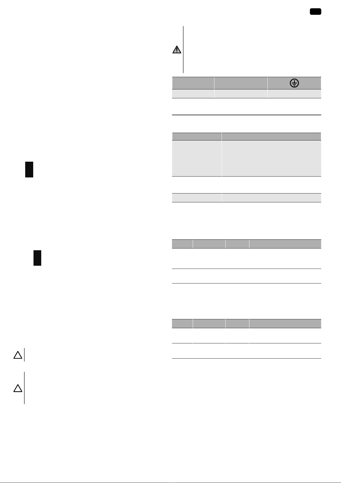
Longueur utile de lisse
Accessoirisation de la lisse
Caoutchouc sous
la lisse (Ref.
9017045)
999 999
Caoutchouc sur
la lisse (Ref.
9017045)
99 99
Kit éclairage led
(Ref. 9020718)
99
Béquille de repos
(Ref. 9020720)
9999
Levixo 60
H3 L min 4,2 m 4,3 m 4,5 m 4,8 m 4,6 m 4,7 m 5 m 4,7 m
Lmax5m5m5m5m5m5m5m6m
H2 L min 2,6 m 3 m 3,2 m 3,4 m 3,3 m 3,4 m 3,6 m 4,1 m
L max 4 m 4,1 m 4,4 m 4,7 m 4,4 m 4,6 m 4,7 m 4,6 m
Levixo 40
H3 L min 2,8 m 2,8 m 2,8 m 2,8 m 2,8 m 2,8 m 4 m 3,8 m
Lmax4m4m4m4m4m4m4m4m
H2 L min 2,2 m 2,3 m 2,5 m 2,6 m 2,6 m 2,6 m 2,6 m 2,9 m
L max 2,7 m 2,7 m 2,7 m 2,7 m 2,7 m 2,7 m 2,7 m 3,7 m
H1 L min 1,4 m 1,4 m 1,5 m 1,6 m 1,7 m 1,8 m 1,9 m 2,1 m
L max 2,2 m 2,3 m 2,5 m 2,6 m 2,6 m 2,7 m 2,7 m 3 m
H1 H1
H2 H2
H3 H3
Montage gauche Montage droite
2.2.Encombrement - Fig. 1
2.3.Installation type - Fig. 2
Rep. Désignation Câble (mm²)
1 Moteur Levixo 40/60 2 x 1,5 + T
2 Lisse -
3 Lyre de repos -
4 Colonne pour cellule photoélectrique 2 x 0,75 + 4 x 0,75
5 Feu orange 2 x 0,75
6 Spirale magnétique câble fourni avec la
spirale magnétique
ref. 9020724
3.INSTALLATION
Attention
Vérifier que le sol est de niveau.
La barrière peut être installée soit directement au sol, soit avec la
plaque de fixation fournie (conseillée pour faciliter la mise à niveau).
La barrière est livrée pour un montage gauche.
3.1.Préparation des fondations
Attention
Avant toute ouverture de la porte du caisson, s’assurer de la
détente du ressort en amenant la lisse en position verticale,
comme sur la figure 15.
La porte du caisson doit être orientée vers l’intérieur de la propriété.
3.1.1.Fondations avec plaque d’assise (en option) et
fondation béton - Fig. 3
1) Creuser une fondation adaptée au type de terrain.
2) Prévoir plusieurs conduites pour le passage des câbles électriques.
3) Placer les 4 vis fournies sur la plaque d’assise en position finale, filet
de vis vers le haut, et souder les têtes des 4 vis à la base. Protéger les
soudures avec de l’antirouille.
4) Positionner la plaque de telle façon qu’elle dépasse d’environ 20 mm
du sol.
Sur la figure 3, les flèches indiquent le sens de circulation des véhicules.
5) Remplir la fondation de béton en contrôlant la position de la plaque
dans les deux sens avec un niveau à bulle et laisser le ciment durcir.
3.1.2.Fondations sans plaque d'assise Fig. 4
1) Placer le caisson au sol.
2) Débander (Fig. 9) puis enlever le ressort pour accèder plus facilement
aux trous de fixation du caisson.
3) Marquer les trous de fixation.
4) Retirer le caisson et percer les trous de fixation.
5) Insérer des chevilles (non fournies) dans les trous de fixation.
La surface supérieure de l’opérateur est légèrement inclinée pour
empêcher la stagnation de l’eau de pluie. Utiliser une surface latérale
pour vérifier que le caisson est bien de niveau.
3.2.Fixation du caisson - Fig. 5
Fixer le caisson en le bloquant avec des écrous M12.
Le fil de terre n'est pas fourni.
3.3.Montage de la lisse - Fig. 6
1) Graisser l'axe avant d'installer la plaque de fixation de la lisse.
2) Placer le fin de course contre sa butée en position verticale selon le
montage gauche (Fig. 7A) ou droite (Fig. 7B) de la barrière. Si besoin,
débrayer (Fig. 15). ATTENTION, le ressort doit avoir été enlevé à cette
étape.
LEVIXO 40/60 24V RTS FR
5Copyright©2017 SOMFY ACTIVITES SA. All rights reserved.
3) Placer la plaque de fixation sur l'axe. Elle doit être parallèle au caisson.
4) Fixer avec la visse fournie dans le kit de fixation.
Serrer la visse va enfoncer en parallèle la plaque de fixation.
5) Visser l'étrier à la plaque de fixation en laissant du jeu afin de faciliter
la pose de la lisse.
L'étrier possède des butées qui permettent de caler la lisse. Placer les
butées vers le bas.
6) Débrayer la lisse (Fig. 15) pour tourner la plaque de fixation avec
l'étrier en position horizontale et insérer la lisse.
7) Débrayer encore une fois pour placer la lisse en position verticale. Une
fois la lisse bien enfoncée sur sa butée, serrer les 4 boulons.
8) Retirer le film protecteur du cache.
3.4.Réglage des fins de course
La barrière est équipée de contacts fin de course électriques réglables et
d'un arrêt mécanique.
Une marge de rotation d'environ 1° doit être maintenue entre le contact
fin de course électrique et l'arrêt mécanique, tant en fermeture qu'en
ouverture, ceci afin de ne pas endommager les contacts fin de course.
Réglage des fins de course mécaniques - Fig. 7
Fig. 7 A: Montage gauche
Fig. 7 B: Montage droite
Légende de la figure
FCC : Fin de course fermeture
FCO : Fin de course ouverture
En position d'ouverture (lisse verticale), laisser 1° en plus afin de
calibrer facilement le fin de course électrique.
3.5.Installation et réglage du ressort - Fig. 8
1) Ouvrir la barrière.
2) Installer l'attache du ressort sur la partie gauche ou droite du fin de
course mécanique selon le côté d'installation de la barrière.
Fig. 8 A: Montage gauche
Fig. 8 B: Montage droite
Le fin de course mécanique comporte 3 trous de fixation selon la
longueur de lisse voulue. Placer l'attache du ressort dans le trou
qui convient à l'installation (voir "Longueur utile de lisse" dans "2.1.
Domaine d'application").
3) Attacher le tendeur du ressort au fin de course mécanique en
respectant bien le schéma de montage.
4) Attacher le ressort au tendeur.
5) Fixer le ressort à la partie basse du caisson en faisant glisser le
ressort dans l'encoche puis en pivotant légérement le ressort avec
un mouvement vers le haut pour faire rentrer celui-ci contre sa butée.
3.6.Equilibrage de la lisse - Fig. 9
Attention
La lisse doit être équilibrée à 45°-50°.
Equilibrer la lisse en ajoutant la tension du ressort.
Attention
Une fois la lisse bien équilibrée, bien serrer les écrous haut et
bas du tendeur afin que les vibrations ne fassent pas bouger ces
derniers. Sinon le ressort ne restera pas en position et l'équilibrage
sera faussé.
3.7.Raccordement électrique - Fig. 10
Avertissement
• Utiliser un câble 3x1,5 mm² pour un usage extérieur (type
H07RN-F minimum).
• Utiliser impérativement les serre-câbles fournis.
• Pour tous les câbles basse tension, s'assurer qu'ils résistent
à une traction de 100 N. Vérifier que les conducteurs n'ont pas
bougés lorsque cette traction est appliquée.
LN
Marron Bleu Jaune/Vert
4.MISE EN SERVICE
4.1.Navigation dans le menu des paramètres
Touches Fonction
OK • 2 appuis pour entrée dans menu des
paramètres
• 1 appui pour valider :
-la sélection d’un paramètre
-la valeur d’un paramètre
+ OU - Navigation dans la liste des paramètres
Modification de la valeur d’un paramètre
+ ET - Sortie du menu de paramétrage
4.2.Réglage du sens d'ouverture de la barrière -
Fig. 11
Par défaut, la barrière est réglée pour un montage à gauche.
Changer le sens d'ouverture de la barrière si elle est installée à droite.
Menu Sous menu Valeur Description
/R*,F ,QX6(Q6
R8Y
0 Sens d'ouverture inversé par
rapport au fonctionnement
standard (barrière droite)
1Fonctionnement standard
(barrière gauche)
4.3.Calibrage des fins de course électronique -
Fig.12
Le calibrage est nécessaire pour que le fin de course mécanique finisse sa
course en douceur sur la butée mécanique.
Menu Sous menu Valeur Description
3$U$0 F$/R8Y 0 à 100
(40)
Calibrage fin de course ouverture
(%)
F$/)(U0 0 à 100
(60)
Calibrage fin de course fermeture
(%)
4.4.Mémorisation des télécommandes - Fig. 13
1) Appuyer 2 s sur la touche PROG de l’unité de commande.
Le voyant s’allume fixe.
2) Appuyer sur la touche de la télécommande qui commandera l’ouverture
de la barrière.
Le voyant clignote, la télécommande est mémorisée.
L’exécution de cette procédure pour un canal déjà mémorisé provoque
l’effacement de celui-ci.
Poursortirdumodeprogrammationsansenregistrerdetélécommande,
faire un appui court sur la touche PROG de l’unité de commande.

FR LEVIXO 40/60 24V RTS
6 Copyright©2017 SOMFY ACTIVITES SA. All rights reserved.
4.5.A vérifier avant toute utilisation
• La longueur de lisse correspond bien à la longueur indiqué dans le
tableau "Longueur utile de lisse".
• Les rondelles et pièces mécaniques composant le tendeur du
ressort sont bien dans l'ordre indiqué sur la figure 8.
• Le ressort est tendu même lorsque la lisse est en position verticale.
• La lisse est bien équilibré à 45-50°.
• Les deux écrous du tendeur sont bien positionnés et verrouillés
comme indiqué sur la figure 9 et suivant la procédure 3.6
"Equilibrage de la lisse".
• Le sens d'ouverture de la barrière et le calibrage en ouverture et
fermeture sont bien paramétrés.
5.UTILISATION
5.1.Utilisation standard des télécommandes - Fig. 14
5.2.Verrouillage/déverrouillage de la lisse - Fig. 15
Attention
Opération à réaliser hors tension.
5.3.Fonctionnement de la détection d’obstacle
Une détection d’obstacle durant la fermeture provoque la ré-ouverture de
la barrière.
5.4.Formation des utilisateurs
Former tous les utilisateurs à l’usage en toute sécurité de cette barrière
(utilisation standard et principe de déverrouillage) et aux vérifications
périodiques obligatoires.
6.RACCORDEMENT DES PÉRIPHÉRIQUES
Danger
Couper l’alimentation électrique du moteur avant toute intervention
sur les périphériques.
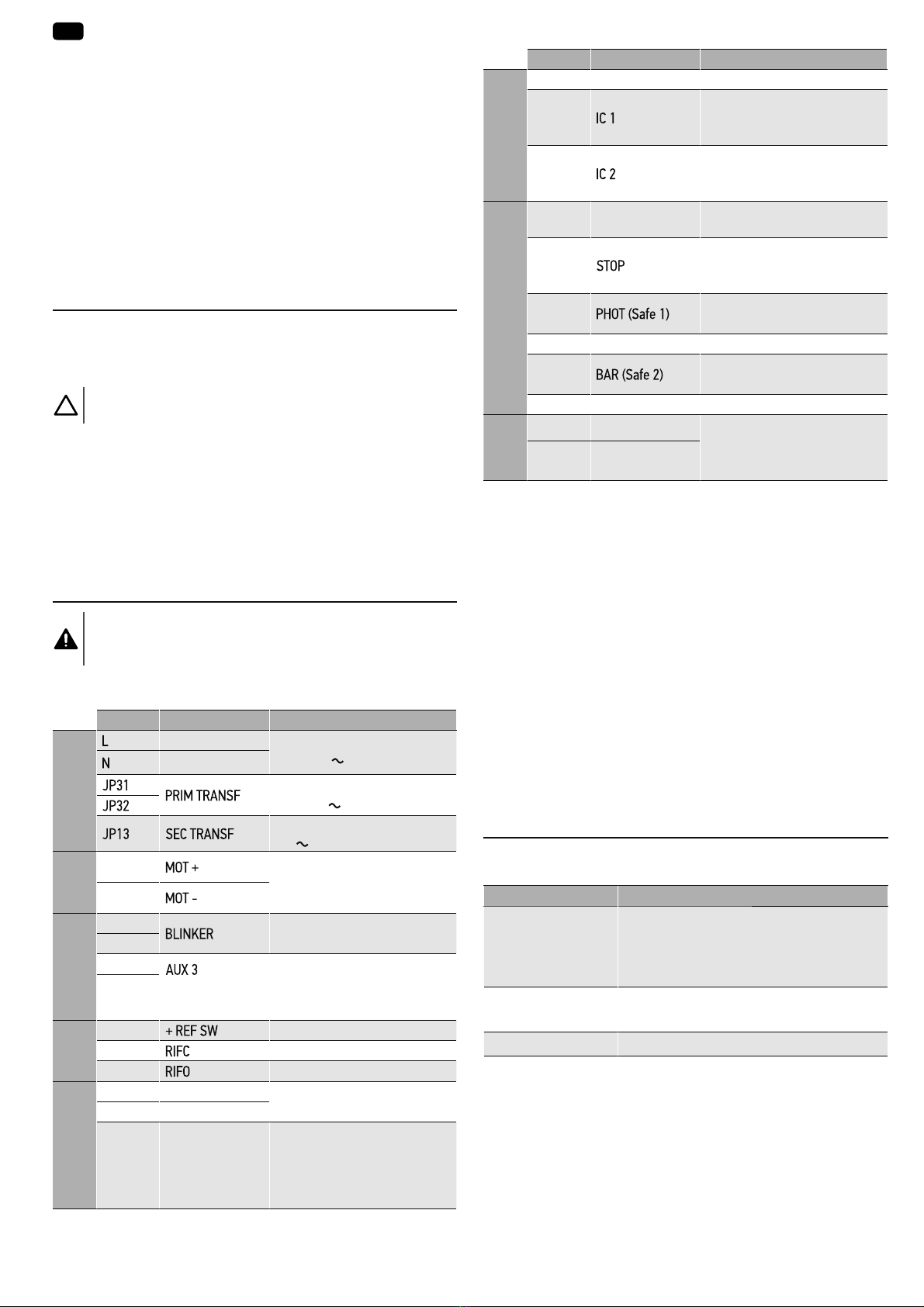
6.1.Plan de câblage général - Fig. 16
Borne Définition Description
Alimentation
Phase Alimentation monophasée
220-230V 50/60 Hz
Neutre
Connexion primaire
transformateur, 220-230V
Alimentation de la carte :
24V Secondaire
transformateur
Moteur
3Connexion moteur 1
4
Aux
7Max 25W
8
9- contact libre
(Max 24V 0,5A)
Sortie configurable AUX 3
Voir "7.2. Liste des paramètres"
10
Fins de
course
12 Commun
13 Fin de course fermeture (NC)
14 Fin de course ouverture (NC)
Borne Définition Description
Alimentation des
accessoires
15 24V- Sortie alimentation accessoires
16 24V+
17 24Vsafe+
Sortie alimentation des
dispositifs de sécurité testés
(cellules photoélectriques et
émetteur barre palpeuse)
Sortie active uniquement
pendant un mouvement
Commandes
18 Commun Commun entrées IC 1 et IC 2
19
Entrée de commande
configurable 1 (NO)
Voir "7.2. Liste des paramètres"
20
Entrée de commande
configurable 2 (NO)
Voir "7.2. Liste des paramètres"
Sécurités
24 Commun Commun entrées STOP, SAFE 1
et SAFE 2
25
La commande interrompt la
manoeuvre (NC)
Si non utilisée, laisser la
barrette en place.
26
Entrée de sécurité configurable
1 (NC)
Voir "7.2. Liste des paramètres"
27 Non utilisée
28
Entrée de sécurité configurable
2 (NF)
Voir "7.2. Liste des paramètres"
29 Non utilisée
Antenne
Y Âme
Antenne déportée
# Tresse
6.2.Description des différents périphériques
6.2.1.Cellules photoélectrique
Sans auto-test- Fig. 17
Avec auto-test - Fig. 18
6.2.2.Feu orange - Fig. 19
6.2.3.Moduleled - Fig. 20
6.2.4.Détecteur de masse métallique - Fig. 21
6.2.5.Antenne
Antenne intégrée
L'antenne intégrée doit être dirigée vers le bas pour un bon fonctionnement.
Antenne déportée - Fig. 22
7.PARAMÉTRAGE AVANCÉ
7.1.Navigation en mode paramétrage
Touches Fonction
OK • 2 appuis pour entrée dans menu des
paramètres
• 1 appui pour valider :
-la sélection d’un paramètre
-la valeur d’un paramètre
+ OU - Navigation dans la liste des paramètres
Modification de la valeur d’un paramètre
+ ET - Sortie du menu de paramétrage

LEVIXO 40/60 24V RTS FR
7Copyright©2017 SOMFY ACTIVITES SA. All rights reserved.
7.2.Liste des paramètres (menus et sous-menus)
Dans le tableau la valeur en gras correpsond à la valeur par défaut.
Menu Sous menu Val. Description
3$U$0 WF$ 0 à 180 (10)Temporisation de la fermeture automatique
F$/R8Y 0 à 100 (40)Calibrage fin de course ouverture (%)
F$/)(U0 0 à 100 (60)Calibrage fin de course fermeture (%)
$FF(/ 1 à 10 (3)Accéleration en début de mouvement (%)
(63G(F(/ 0 à 99 (70) Distance de décélération (passage de la vitesse de régime à la vitesse de ralentissement) à
l’ouverture et à la fermeture exprimée en pourcentage de la course totale.
)RUF(R8Y 40 à 99 (75)Force exercée par la barrière à l'ouverture (%)
)RUF()(U0 40 à 99 (75)Force exercée par la barrière à la fermeture (%)
)U(,Q 1 à 10 (2)Freinage pendant la phase de ralentissement (%)
X,WR8Y 15 à 99 (75) Vitesse ouverture (%)
Réglage de la vitesse que la barrière doit atteindre à l'ouverture, en pourcentage de la vitesse
maximum atteignable par la barrière.
X,W)(U0 15 à 99 (75) Vitesse fermeture (%)
Réglage de la vitesse que la barrière doit atteindre à la fermeture, en pourcentage de la vitesse
maximum atteignable par la barrière.
/R*,F WF$ 0Fermeture automatique non active
1Fermeture automatique active
)(U$3 0Fermeture rapide non active
1 Fermeture rapide active: fermeture 1s après le dégagement des cellules, sans attendre la fin de la
temporisation de fermeture automatique configurée
0R8YW3$6$
3$6
0Fonctionnement 4 pas des
entrées configurées en
Radio 2 PAS 3 PAS 4 PAS
Fermée Ouvre Ouvre Ouvre
En fermeture Stop
Ouverte
Ferme
Ferme Ferme
En ouverture Stop + Tempo
de fermeture
Stop + Tempo
de fermeture
Après STOP Ouvre Ouvre Ouvre
1 Fonctionnement 3 pas des
entrées configurées en
Radio. Une commande en
cours de fermeture inverse
le mouvement.
2 Fonctionnement 2 pas
des entrées configurées
en Radio. Une commande
en cours de fermeture
ou d'ouverture inverse le
mouvement
3U($/ 0Sans préavis avant mouvement
1Avec préavis de 3s avant mouvement
KR00(0RUW( 0Fonctionnement impulsionnel
1 Fonctionnement "Homme mort"
• Entrée 19 configurée comme OPEN UP
• Entrée 20 configurée comme CLOSE UP
Pilotage par action maintenue
Attention
Dispositifs de sécurité inactifs
2 Fonctionnement "Homme mort" d'urgence s'active en cas d'échec des autotests des dispositifs
de sécurité (cellules photoélectriques, ...) 3 fois de suite. Actif 1 minute après avoir relâché les
touches OPEN UP - CLOSE UP.
• Entrée 19 configurée comme OPEN UP
• Entrée 20 configurée comme CLOSE UP
Attention
Dispositifs de sécurité inactifs
E/,03R8Y 0Impulsion des entrées configurées en Radio prend effet pendant l'ouverture.
1Impulsion des entrées configurées en Radio ne prend pas effet pendant l'ouverture.
E/,03WF$ 0Impulsion des entrées configurées en Radio prend effet pendant l'ouverture TCA.
1Impulsion des entrées configurées en Radio ne prend pas effet pendant la pause TCA.
E/,)( 0Impulsion des entrées configurées en Radio prend effet pendant la fermeture.
1Impulsion des entrées configurées en Radio ne prend pas effet pendant la fermeture.
,QX6(Q6R8Y 0Sens d'ouverture inversé par rapport au fonctionnement standard (barrière droite)
1Fonctionnement standard (barrière gauche)

FR LEVIXO 40/60 24V RTS
8 Copyright©2017 SOMFY ACTIVITES SA. All rights reserved.
Menu Sous menu Val. Description
6$)(/6$)( 0 Entrée de sécurité cellules active sans auto-test.
Les cellules sont actives à l'ouverture et à la fermeture. En fermeture, inversion du mouvement
lorsque les cellules ne sont plus occultées.
1 Entrée de sécurité cellules actives avec auto-test.
L’auto test du dispositif s’effectue au début du mouvement.
Les cellules sont actives à l'ouverture et à la fermeture. En fermeture, inversion du mouvement
lorsque les cellules ne sont plus occultées.
2 Entrée de sécurité cellules active sans auto-test.
Les cellules sont actives à l'ouverture et à la fermeture. En fermeture, inversion du mouvement
lorsque les cellules ne sont plus occultées.
3Indisponible
4Entrée de sécurité cellules active sans auto-test.
Les cellules sont actives à la fermeture seulement. En cas d'activation, inversion du mouvement
lorsque les cellules ne sont plus occultées.
5 Entrée de sécurité cellules active avec auto-test.
Les cellules sont actives à la fermeture seulement. En cas d'activation, inversion du mouvement
lorsque les cellules ne sont plus occultées.
6 Entrée de sécurité barre palpeuse active sans auto-test
En cas d'activation, inversion du mouvement pendant 2 s.
7 Entrée de sécurité barre palpeuse active avec auto-test
L’auto test du dispositif s’effectue au début du mouvement.
En cas d'activation, inversion du mouvement pendant 2 s.
,F/,F 0 Entrée configurée en Radio
Fonctionnement suivant la logique MoUvt PAS A PAS
1Indisponible
2Entrée configurée comme Open
Une commande entraîne l'ouverture de la barrière. Si l’entrée reste fermée, la barrière reste
ouverte jusqu’à l’ouverture du contact. Avec le contact ouvert, la barrière se ferme après la
temporisation de fermeture automatique, si elle est activée.
3 Entrée configurée comme Close
Une commande entraîne la fermeture de la barrière.
4Indisponible
5 Entrée configurée comme Timer
Fonctionnement identique à Open mais la fermeture est garantie même après une panne de
courant.
$8;
(Auxiliare 3) 1Sortie Voyant barrière ouverte SCA
Contact fermé pendant l’ouverture et lorsque la barrière est ouverte, intermittent pendant la
fermeture, ouvert avec la barrière fermée.
2Sortie commande Lumière de courtoisie
Contact fermé pendant 90s après le dernier mouvement
12 Sortie état barrière
Contact fermé lorsque la barrière est complètement fermée
'()$8/W Retour en configuration d'usine de l'unité de commande
/$Q*8$*( ,W$
)U$
G(8
(Q* Valeur par défaut
(63
6W$W Y(U6 Version de logiciel de l'unité de commande
QF<F/(6 Nombre de cycles (par centaines)

LEVIXO 40/60 24V RTS FR
9Copyright©2017 SOMFY ACTIVITES SA. All rights reserved.
8.EFFACEMENT DES TÉLÉCOMMANDES ET
DE TOUS LES RÉGLAGES
8.1.Effacement des réglages - Fig. 23
Attention
En cas d'effacement des réglages, les paramètres reviendront
aux valeurs d'usine. Il est important de régler à nouveau le
sens d'ouverture de la barrière et de calibrer les fins de course
électroniques.
1) Sélectionner '()$8/W dans le menu de l'unité de commande.
2) Appuyer sur OK de l'unité de commande pour confirmer le retour en
configuration d'usine de l'unité de commande.
8.2.Effacement des télécommandes mémorisées -
Fig.24
Appuyer 7s sur PROG de l'unité de commande.
Le voyant clignote lentement, toutes les télécommandes sont effacées.
9.DIAGNOSTIC ET DÉPANNAGES
9.1.Diagnostic
Code Description Commentaire
6WU( Activation entrée Start
externe Radio
R3(Q Activation entrée OPEN
F/6 Activation entrée CLOSE
W,0H Activation entrée TIMER
6WR3 Activation entrée STOP
3KRW Activation entrée cellules
photoélectriques PHOT
ou si configurée comme
cellules actives avec auto-
test activation de l'entrée
FAULT associée
E$U Activation entrée barre
palpeuse ou si configurée
comme barre palpeuse
active avec auto-test
activation de l'entrée
FAULT associée
6:& Activation entrée fin de
course fermeture du
moteur
6:R Activation entrée fin de
course ouverture du
moteur
(U Echec auto-test cellules
photoélectriques
Vérifier raccordement et/ou
paramétrage.
(U Echec auto-test barre
palpeuse
Vérifier raccordement et/ou
paramétrage.
(U;*Erreur essai matériel carte Vérifier les raccordements sur
le moteur.
Problèmes matériels sur la
carte, contacter Somfy.
(U[*Erreur de l'encodeur Vérifier le câblage et la carte de
l'encodeur, éventuellement le
sens du moteur et remettre la
carte en configuration d'usine.
(U[*Détection d'obstacle Vérifier la présence d'un
obstacle.
Code Description Commentaire
(U[*Thermique Attendre le refroidissement de
l'automatisme.
(U
(U
(U
(U
Erreur interne de contrôle
supervision système
Essayer d'éteindre et de
rallumer la carte. Si le problème
persiste, contacter Somfy.
HU Erreur de cohérence des
paramètres de l'unité de
commande (/R*,F et
3$U$0)
Un appui sur OK confirmera les
paramètres détectés. La carte
continuera à fonctionner avec
les paramètres détectés.
Attention
Vérifier le paramétrage
(/R*,F et 3$U$0).
(U Erreur dans les
paramètres de D-track
Si appui sur OK, la carte
continuera à fonctionner avec
D-track par défaut.
Attention
Une auto-configuration est
requise.
(U)[*Erreur fin de course Vérifier le câblage des fins de
course.
*[= 0, 1, ....., 9, A, B, C, D, E, F
10. CARACTÉRISTIQUES TECHNIQUES
Barrière
Alimentation secteur 220-230Vac 50/60Hz
Tension du moteur 24Vdc
Puissance absorbée 300W
Couple maximum 130Nm (Levixo40) / 260Nm (Levixo60)
Fin de course Mécanique et réglage électrique
Détection d'obstacle Encodeur (optique)
Déverrouillage Clé individuelle
Vitesse 2,5s à 6s (Levixo40) / 3s à 9s (Levixo60)
Longueur de lisse
maximum 4m sans accessoires (Levixo40) / 6m sans
accessoires (Levixo60)
Conditions climatiques
d’utilisation - 20 ° C / + 55 ° C - IP 54
Utilisation - Nombre de
cycles maximum Intensive - 85 cycles / heure (environ 2000
cycles/jour)
Poids (sans lisse) 40 kg
Unité de commande
Protection contre les
surcharges et court-
circuits
Logiciel
Fusibles F1 (2A), F3 (1,25AT), F4 (1,25AT)
- Fig.16
Alimentation des
accessoires 24V (intensité maximum 0,5A)
24V (auto-test)
AUX 0 Contact alimenté NO (24V / 1A max.)
AUX 3 Contact NO (24V / 1A max.)
Fréquence radio 433,42 MHz
< 10 mW
Nombre de canaux
mémorisables 128
Interface de
programmation Ecran LCD - 4 boutons

EN LEVIXO 40/60 24V RTS
2 Copyright©2017 SOMFY ACTIVITES SA. All rights reserved.
DANGER
The motorisation must be installed and adjusted by a pro-
fessional motorisation and home automation installer, in
compliance with the regulations of the country in which it
is to be used.
Failure to follow these instructions may result in serious in-
jury, e.g. due to crushing by the barrier.
1.1.Caution - Important safety instructions
WARNING
For reasons of personal safety, it is important to follow all
the instructions, as incorrect installation can lead to serious
injury. Retain these instructions.
The installer must train all users to ensure the motorisation
is used in complete safety.
The user manual must be given to the end user. The installer
must explain clearly to the user that installation, adjustment
and maintenance of the motorisation must be performed by
a professional motorisation and home automation installer.
1.2.Introduction
1.2.1.Important information
This product is a barrier to be used exclusively for motorised ve-
hicles. The main purpose of these instructions is to satisfy the
requirements of the aforementioned standard and to ensure the
safety of equipment and persons.
WARNING
The barrier must only be used to allow vehicles to
pass through. It is strictly prohibited for pedestrians
to enter the operating zone of the barrier. It is necessary
to provide a separate pedestrian route.
WARNING
Any use of this product outside the scope of application de-
scribed in these instructions is prohibited (see “Field of ap-
plication” paragraph in the installation manual).
The use of any accessories or components not recommend-
ed by Somfy is prohibited, as personal safety cannot be
guaranteed.
TRANSLATED VERSION OF THE GUIDE
CONTENTS
GENERAL INFORMATION
Safety instructions
Danger
Indicates a danger which may result in immediate death or serious injury.
Warning
Indicates a danger which may result in death or serious injury.
Precaution
Indicates a danger which may result in minor or moderate injury.
Attention
Indicates a danger which may result in damage to or destruction of the product.
1.SAFETY INSTRUCTIONS
1. Safety instructions 2
1.1. Caution - Important safety instructions 2
1.2. Introduction 2
1.3. Preliminary checks 3
1.4. Electrical installation 3
1.5. Handling precautions 3
1.6. Clothing precautions 3
1.7. Safety instructions relating to installation 3
1.8. Safety instructions relating to use 3
1.9. Safety instructions relating to maintenance 3
1.10.Regulations 4
1.11.Assistance 4
2. Product description 4
2.1. Scope of application 4
2.2. Dimensions - Fig. 1 4
2.3. Standard installation - Fig. 2 4
3. Installation 4
3.1. Preparing the base 4
3.2. Mounting the housing - Fig. 5 4
3.3. Mounting the boom - Fig. 6 4
3.4. Setting the end limits 5
3.5. Installing and setting the spring - Fig. 8 5
3.6. Balancing the boom - Fig. 9 5
3.7. Electrical connection - Fig. 10 5
4. Commissioning 5
4.1. Navigating the settings menu 5
4.2. Setting the opening direction of the barrier - Fig. 11 5
4.3. Calibrating the electronic end limits - Fig.12 5
4.4. Programming the remote controls - Fig. 13 5
4.5. To be checked always before use 6
5. Use 6
5.1. Standard use of the remote controls - Fig. 14 6
5.2. Locking/unlocking the boom - Fig. 15 6
5.3. Obstacle detection operation 6
5.4. User training 6
6. Connecting additional devices 6
6.1. General wiring diagram - Fig. 16 6
6.2. Description of the various additional devices 6
7. Advanced parameter setting 6
7.1. Navigating in parameter setting mode 6
7.2. List of settings (menus and sub-menus) 7
8. Clearing the remote controls and all settings 9
8.1. Clearing the settings - Fig. 23 9
8.2. Clearing the memorised remote controls - Fig 24 9
9. Diagnostic and troubleshooting 9
9.1. Diagnostics 9
10. Technical data 9

LEVIXO 40/60 24V RTS EN
3Copyright©2017 SOMFY ACTIVITES SA. All rights reserved.
Any failure to comply with the instructions given in this manual
shall exclude Somfy from all liability and invalidate the Somfy
warranty.
If in any doubt when installing the motorisation or to obtain addi-
tional information, visit the website www.somfy.com.
The instructions may be modified if and when there is a change in
the standards or the motorisation.
1.3.Preliminary checks
1.3.1.Installation environment
ATTENTION
Do not spray water onto the motorisation.
Do not install the motorisation in an explosive environment.
Check that the temperature range marked on the motorisa-
tion is suited to the installation location.
DANGER
CAUTION: It is dangerous to perform any operation on the
barrier springs.
1.3.2.Specifications of the barrier to be motorised
Aer installation, ensure that the parts of the barrier do not en-
croach onto the pavement or public thoroughfare.
1.4.Electrical installation
DANGER
The installation of the power supply must comply with the
standards in force in the country in which the motorisation
is installed, and must be carried out by qualified personnel.
The electric line must be exclusively reserved for the motor-
isation and equipped with protection, comprising:
• a 10 A fuse or breaker,
• a differential type device (30 mA).
An all-pole power supply cut-off device must be provided.
The switches provided to ensure a cut-out of all poles on
fixed appliances must be connected to the power supply ter-
minals and there must be a separation between the contacts
on all poles to ensure complete disconnection in conditions
where category III high impulse voltage is present.
Low-voltage cables subject to inclement weather must be at
least of type H07RN-F.
It is recommended that you fit a lightning conductor (maxi-
mum residual voltage 2 kV).
Cable feed
Underground cables must be equipped with a protective sheath
with a sufficient diameter to contain the motor cable and the ac-
cessories cables.
For overground cables, use a cable grommet that will withstand
the weight of vehicles (ref. 2400484).
1.5.Handling precautions
Use appropriate handling tools (shape, size and weight of the
load), for example a transport trolley.
1.6.Clothing precautions
Take off any jewellery (bracelet, chain, etc.) during installation.
For manoeuvring, drilling and welding operations, wear appro-
priate protection (special glasses, gloves, ear protection, etc.).
1.7.Safety instructions relating to installation
DANGER
Do not connect the motorisation to a power supply source
(mains) until installation is complete.
WARNING
Ensure that any danger zones (crushing, cutting, trapping)
between the motorised section and the surrounding fixed
sections created by the opening of the motorised section are
avoided or indicated on the installation.
WARNING
Modifying any of the components in this kit or using ad-
ditional components not recommended in this manual is
strictly prohibited.
Monitor the barrier as it moves and keep people away from it.
Do not use adhesive to secure the motorisation.
WARNING
Manual unlocking may result in uncontrolled movement of
the barrier.
Aer installation, ensure that:
• the mechanism is correctly adjusted
• the manual back release device is operating correctly
WARNING
For operation in automatic mode or remote control, photo-
electric cells must be installed.
In automatic mode, the motorisation operates in at least one
direction with no intentional activation by the user.
For operation in automatic mode, or if the barrier faces a public
road, installation of an orange light may be required in accord-
ance with the regulations in the country in which the motorisation
is commissioned.
1.8.Safety instructions relating to use
WARNING
This motorisation may be used by children aged 8 and over
and by persons whose physical, sensory or mental capacity
is impaired, or persons with little experience or knowledge,
as long as they are under supervision or have received in-
structions on safe use of the motorisation and fully under-
stand the associated risks.
Children must not be allowed to play with the motorisation.
Do not allow children to play with the barrier control devices.
Keep remote controls out of the reach of children.
Children must not be allowed to clean or maintain the unit.
1.9.Safety instructions relating to maintenance
DANGER
The motorisation must be disconnected from any power
supply during cleaning and maintenance and when parts are
replaced.
EN LEVIXO 40/60 24V RTS
4 Copyright©2017 SOMFY ACTIVITES SA. All rights reserved.
1.10. Regulations
Somfy declares that, when used in accordance with these in-
structions, the product described in these instructions complies
with the essential requirements of the applicable European direc-
tives, and in particular Machinery Directive 2006/42/EC and Radio
Equipment Directive 2014/53/EU.
The full text of the EC declaration of conformity is available at the
following website: www.somfy.com/ce.
Antoine CREZE, Head of Regulations, Cluses
1.11. Assistance
You may encounter difficulties or have questions when installing
your motorisation.
Do not hesitate to contact us; our specialists are on hand to an-
swer all your questions.
Internet: www.somfy.com
2.PRODUCT DESCRIPTION
2.1.Scope of application
This motorisation is intended exclusively for a barrier for residential and
collective use and for vehicles only.
Useful boom length
Boom accessories
Rubber under
the boom (ref.
9017045)
999 999
Rubber on the
boom (ref.
9017045)
99 99
LED lighting kit
(ref. 9020718)
99
Rest fork (ref.
9020720)
9999
Levixo 60
H3 Min. L 4.2 m 4.3 m 4.5 m 4.8 m 4.6 m 4.7 m 5 m 4.7 m
Max. L 5 m 5 m 5 m 5 m 5 m 5 m 5 m 6 m
H2 Min. L 2.6 m 3 m 3.2 m 3.4 m 3.3 m 3.4 m 3.6 m 4.1 m
Max. L 4 m 4.1 m 4.4 m 4.7 m 4.4 m 4.6 m 4.7 m 4.6 m
Levixo 40
H3 Min. L 2.8 m 2.8 m 2.8 m 2.8 m 2.8 m 2.8 m 4 m 3.8 m
Max. L 4 m 4 m 4 m 4 m 4 m 4 m 4 m 4 m
H2 Min. L 2.2 m 2.3 m 2.5 m 2.6 m 2.6 m 2.6 m 2.6 m 2.9 m
Max. L 2.7 m 2.7 m 2.7 m 2.7 m 2.7 m 2.7 m 2.7 m 3.7 m
H1 Min. L 1.4 m 1.4 m 1.5 m 1.6 m 1.7 m 1.8 m 1.9 m 2.1 m
Max. L 2.2 m 2.3 m 2.5 m 2.6 m 2.6 m 2.7 m 2.7 m 3 m
H1 H1
H2 H2
H3 H3
Le-sided mounting Right-sided mounting
2.2.Dimensions - Fig. 1
2.3.Standard installation - Fig. 2
No. Description Cable (mm²)
1 Levixo 40/60 motor 2 x 1.5 + T
2 Boom -
3 Rest fork -
4 Pillar for photoelectric cell 2 x 0.75 + 4 x 0.75
5 Orange light 2 x 0.75
6 Magnetic coil Cable provided with
the magnetic coil
ref. 9020724
3.INSTALLATION
Attention
Check that the ground is level.
The barrier can be installed either directly on the ground or using the
mounting plate provided (recommended for easier levelling).
The barrier is supplied for le-hand mounting.
3.1.Preparing the base
Attention
Before opening the door of the housing, it is essential to ensure that
the spring is released by moving the boom to the vertical position
as shown in figure 15.
The door of the housing must be facing inside the property.
3.1.1.Foundations with a base plate (optional) and con-
crete foundation - Fig. 3
1) Make a hole in the base suitable for the type of terrain.
2) Use several ducts to route the electrical cables.
3) Place the 4 bolts supplied with the base plate in the final position with
the thread of the bolt facing upwards and weld the heads of the 4 bolts
to the base. Protect the welds with an anti-rust product.
4) Position the plate so that it protrudes from the ground by approximate-
ly 20 mm.
In figure 3, the arrows indicate the direction in which the vehicles drive.
5) Fill the base with concrete, using a spirit level to check the position of
the plate in both directions, and leave the cement to harden.
3.1.2.Foundations without base plate - Fig. 4
1) Place the housing on the ground.
2) Unhook (Fig. 9) then remove the spring for easier access to the hous-
ing mounting holes.
3) Mark the mounting holes.
4) Remove the housing and drill the mounting holes.
5) Insert plugs (not provided) in the mounting holes.
The top surface of the actuator is angled slightly to prevent rain water
from collecting. Use a side surface to check that the housing is level.
3.2.Mounting the housing - Fig. 5
Secure the housing using M12 nuts.
The earth wire is not provided.
3.3.Mounting the boom - Fig. 6
1) Lubricate the sha before installing the boom mounting plate.
2) Place the end limit against its stop block in the vertical position ac-
cording to whether the barrier is mounted on the le-hand side (Fig.
7A) or right-hand side (Fig. 7B). Disengage if necessary (Fig. 15).
IMPORTANT: the spring must have been remove at this stage.
3) Place the mounting plate on the sha. It must be parallel to the housing.

LEVIXO 40/60 24V RTS EN
5Copyright©2017 SOMFY ACTIVITES SA. All rights reserved.
4) Secure using the bolt provided in the mounting kit.
Tightening the bolt will drive the mounting plate down parallel.
5) Screw the calliper to the mounting plate, leaving enough play to facil-
itate assembly of the boom.
The calliper is fitted with stops allowing the boom to be blocked. Place
the stops towards the bottom.
6) Disengage the boom (Fig. 15) to turn the mounting plate and calliper to
the horizontal position and insert the boom.
7) Disengage again to place the boom in the vertical position. Once the
boom is fitted firmly onto its stop, tighten the 4 bolts.
8) Remove the protective film from the cover.
3.4.Setting the end limits
The barrier is fitted with adjustable electrical end limit contacts and a me-
chanical stop.
A rotation margin of approximately 1° must be le between the electrical
end limit contact and the mechanical stop, both for opening and closing, in
order to prevent damage to the end limit contacts.
Setting the mechanical end limits - Fig. 7
Fig. 7 A: Le-sided mounting
Fig. 7 B: Right-sided mounting
Key
FCC: Closing end limit
FCO: Opening end limit
In the open position (vertical boom), leave an additional 1° in order to
facilitate calibration of the electrical end limit.
3.5.Installing and setting the spring - Fig. 8
1) Open the barrier.
2) Install the spring connector on the le-hand or right-hand section of
the mechanical end limit according to the side on which the barrier is
to be installed.
Fig. 8 A: Le-sided mounting
Fig. 8 B: Right-sided mounting
The mechanical end limit has 3 mounting holes according to the de-
sired length of boom. Place the spring connector in the appropriate
hole for the installation (see "Useful boom length" in "2.1. Scope of
application").
3) Fasten the spring tensioner to the mechanical end limit in accordance
with the assembly diagram.
4) Fasten the spring to the tensioner.
5) Secure the spring to the lower section of the housing by sliding the
spring into the notch then turning the spring upwards slightly so that it
pushes against its stop.
3.6.Balancing the boom - Fig. 9
Attention
The boom must be balanced at 45°-50°.
Balance the boom by increasing the tension of the spring.
Attention
Once the boom is balanced, tighten the top and bottom nuts of the
tensioner so that the vibrations do not cause the nuts to move.
Otherwise, the spring will not remain in position and the boom will
not be correctly balanced.
3.7.Electrical connection - Fig. 10
Warning
• Use a 3x1.5 mm² cable for use outside (min. type H07RN-F).
• The cable clamps supplied must be used.
• For all low-voltage cables, ensure that they can withstand trac-
tion of 100 N. Check that the conductors have not moved when
this traction is applied.
LN
Brown Blue Yellow/Green
4.COMMISSIONING
4.1.Navigating the settings menu
Buttons Function
OK • Press twice to access the settings menu
• Press once to confirm:
-the parameter selection
-the parameter value
+ OR - Navigating the parameter list
Modifying the value of a setting
+ AND - Exiting the settings menu
4.2.Setting the opening direction of the barrier -
Fig. 11
The barrier is set for le-hand mounting as standard.
Change the opening direction of the barrier in the event of right-handing
mounting.
Menu Sub-menu Value Description
/R*,F ,QX6(Q6
R8Y
0 Opening direction reversed in
relation to standard operation
(right-hand barrier)
1Standard operation (le-hand
barrier)
4.3.Calibrating the electronic end limits - Fig.12
Calibration is required so that the mechanical end limit ends its travel gen-
tly on the mechanical stop.
Menu Sub-menu Value Description
3$U$0 F$/R8Y 0 to 100
(40)
Calibrating the opening end limit
(%)
F$/)(U0 0 to 100
(60)
Calibrating the closing end limit
(%)
4.4.Programming the remote controls - Fig. 13
1) Press the PROG button on the control unit for 2 seconds.
The indicator light is lit constantly.
2) Press the button on the remote control which will open the barrier.
The indicator light flashes; the remote control has been stored.
If this procedure is carried out using a channel which has already been
memorised, this channel will be cleared.
To exit programming mode without programming a remote control:
briefly press the PROGbutton on the control unit.
EN LEVIXO 40/60 24V RTS
6 Copyright©2017 SOMFY ACTIVITES SA. All rights reserved.
4.5.To be checked always before use
• The length of the boom corresponds to the length indicated in the
"Useful boom length" table.
• The washers and mechanical parts comprising the spring tensioner
are in the order indicated in figure 8.
• The spring is taut even when the boom is in the vertical position.
• The boom is well balanced at 45-50°.
• The two tensioner nuts are correctly positioned and locked as in-
dicated in figure 9 and according to procedure 3.6 "Balancing the
boom".
• The opening direction of the barrier and the opening/closing calibra-
tion are correctly configured.
5.USE
5.1.Standard use of the remote controls - Fig. 14
5.2.Locking/unlocking the boom - Fig. 15
Attention
Operation to be carried out with the power off.
5.3.Obstacle detection operation
When an obstacle is detected during closing, the barrier re-opens.
5.4.User training
All users must be trained on how to safely use this barrier (standard use
and locking principle) and on the mandatory periodic checks.
6.CONNECTING ADDITIONAL DEVICES
Danger
Switch off the electrical supply to the motor before performing any
operation on the additional devices.
6.1.General wiring diagram - Fig. 16
Terminal Definition Description
Power supply
Live Single-phase power supply
220-230V 50/60 Hz
Neutral
Primary transformer connection,
220-230V
Board power supply:
24V Secondary transformer
Motor
3Motor 1 connection
4
Aux
7Max. 25W
8
9- free
contact
(max. 24 V 0.5 A)
Configurable output AUX 3
See "7.2. List of settings"
10
End
limits
12 Common
13 Closing end limit (NC)
14 Opening end limit (NC)
Accessories power
supply
15 24V- Accessories power supply
output
16 24V+
17 24Vsafe+
Power supply output for safety
mechanisms tested (photo-
electric cells and safety edge
transmitter)
Output active only when moving
Terminal Definition Description
Commands
18 Common IC 1 and IC 2 inputs common
19
Configurable command input
1 (NO)
See "7.2. List of settings"
20
Configurable command input
2 (NO)
See "7.2. List of settings"
Safety devices
24 Common STOP, SAFE 1 and SAFE 2
outputs common
25
The command interrupts the
manoeuvre (NC)
If not used, leave the lug in place.
26 Configurable safety input 1 (NC)
See "7.2. List of settings"
27 Not used
28 Configurable safety input 2 (NF)
See "7.2. List of settings"
29 Not used
Aerial
Y Conductor
Offset aerial
# Braid
6.2.Description of the various additional devices
6.2.1.Photoelectric cells
Without auto-test- Fig. 17
With auto-test - Fig. 18
6.2.2.Orange light - Fig. 19
6.2.3.LED module - Fig. 20
6.2.4.Metal detector - Fig. 21
6.2.5.Aerial
Integrated antenna
The integrated aerial must be directed downwards to the system operates
correctly.
Offset antenna - Fig. 22
7.ADVANCED PARAMETER SETTING
7.1.Navigating in parameter setting mode
Buttons Function
OK • Press twice to access the settings menu
• Press once to confirm:
-the parameter selection
-the parameter value
+ OR - Navigating the parameter list
Modifying the value of a setting
+ AND - Exiting the settings menu

LEVIXO 40/60 24V RTS EN
7Copyright©2017 SOMFY ACTIVITES SA. All rights reserved.
7.2.List of settings (menus and sub-menus)
In the table, the value in bold type corresponds to the default value.
Menu Sub-menu Val. Description
3$U$0 WF$ 0 to 180 (10)Automatic closing timeout
F$/R8Y 0 to 100 (40)Calibrating the opening end limit (%)
F$/)(U0 0 to 100 (60)Calibrating the closing end limit (%)
$FF(/ 1 to 10 (3)Acceleration at start of movement (%)
(63G(F(/ 0 to 99 (70) Deceleration distance (shi from operating speed to slowing speed) when opening and closing
expressed as a percentage of the total travel.
)RUF(R8Y 40 to 99 (75)Force exerted by the barrier when opening (%)
)RUF()(U0 40 to 99 (75)Force exerted by the barrier when closing (%)
)U(,Q 1 to 10 (2)Braking during slowing phase (%)
X,WR8Y 15 to 99 (75) Opening speed (%)
Setting of speed the barrier much reach when opening as a percentage of the maximum speed that
can be reached by the barrier.
X,W)(U0 15 to 99 (75) Closing speed (%)
Setting of speed the barrier much reach when closing as a percentage of the maximum speed that
can be reached by the barrier.
/R*,F WF$ 0Automatic closing not activated
1Automatic closing activated
)(U$3 0Quick closing not activated
1 Quick closing activated: closing 1s aer the cells are cleared without waiting for the end of the
automatic closing timeout configured
67(3%<67(3
PRYHPHQW
0Operation 4 steps from the
radio-configured inputs 2 STEPS 3 STEPS 4 STEPS
Closed Open Open Open
When closing Stop
opened
Close
Close Close
Opening Stop + closing
timeout
Stop + closing
timeout
Aer STOP Open Open Open
1 Operation 3 steps from
the radio-configured
inputs. A command sent
when closing reverses the
movement .
2 Operation 2 steps from the
radio-configured inputs. A
command sent when clos-
ing or opening reverses the
movement
3U($/ 0Without notice before movement
1With 3s warning prior to movement
KR00(0RUW( 0Pulse-controlled operation
1 "Dead man" operation
• Input 19 configured as OPEN UP
• Input 20 configured as CLOSED UP
Controlled by maintained action
Attention
Safety devices inactive
2 Emergency "dead man" operation is activated if the safety mechanism (photoelectric cells, etc.)
auto-tests fail 3 times in succession. Active 1 minute aer releasing the OPEN UP - CLOSE UP
buttons.
• Input 19 configured as OPEN UP
• Input 20 configured as CLOSED UP
Attention
Safety devices inactive
E/,03R8Y 0Pulse of radio-configured inputs takes effect during opening.
1Pulse of radio-configured inputs does not take effect during opening.
E/,03WF$ 0Pulse of radio-configured inputs takes effect during TCA opening.
1Pulse of radio-configured inputs does not take effect during TCA pause.
E/,)( 0Pulse of radio-configured inputs takes effect during closing.
1Pulse of radio-configured inputs does not take effect during closing.
,QX6(Q6R8Y 0Opening direction reversed in relation to standard operation (right-hand barrier)
1Standard operation (le-hand barrier)

EN LEVIXO 40/60 24V RTS
8 Copyright©2017 SOMFY ACTIVITES SA. All rights reserved.
Menu Sub-menu Val. Description
6$)(/6$)( 0 Cell safety input active without auto-test.
The cells are active at opening and closing. When closing, movement inverted if the cells are not
obscured.
1 Cell safety input active with auto-test.
The mechanism's auto-test is conducted at the start of the movement.
The cells are active at opening and closing. When closing, movement inverted if the cells are not
obscured.
2 Cell safety input active without auto-test.
The cells are active at opening and closing. When closing, movement inverted if the cells are not
obscured.
3Unavailable
4Cell safety input active without auto-test.
The cells are only active when closing. In the event of activation, movement inverted
when the cells are no longer blocked.
5 Cell safety input active with auto-test.
The cells are only active when closing. In the event of activation, movement inverted
when the cells are no longer blocked.
6 Safety edge safety input active without auto-test
In the event of activation, movement inverted for 2 s.
7 Safety edge safety input active with auto-test
The mechanism's auto-test is conducted at the start of the movement.
In the event of activation, movement inverted for 2 s.
,F/,F 0 Radio-configured input
Operation in accordance with STEP BY STEP movt rationale
1Unavailable
2Input configured as open
A command causes the barrier to open. If the input remains closed, the barrier remains open until
the contact is opened. With the contact open, the barrier closes aer the automatic closing timeout
if this is activated.
3 Input configured as closed
A command causes the barrier to close.
4Unavailable
5 Input configured as timer
Identical operation to "Open" but closing is guaranteed even in the event of a power cut.
$8;
(auxiliary 3) 1SCA barrier open indicator light output
Contact closed when opening and when the barrier is open, intermittent during closing, open with
barrier closed.
2Courtesy lighting command output
Contact closed for 90seconds aer the last movement
12 Barrier status output
Contact closed when the barrier is completely closed
'()$8/W Control unit reset to factory configuration
/$Q*8$*( ,W$
)U$
G(8
(Q* Default value
(63
6W$W Y(U6 Control unit soware version
QF<F/(6 Number of cycles (per hundreds)

LEVIXO 40/60 24V RTS EN
9Copyright©2017 SOMFY ACTIVITES SA. All rights reserved.
8.CLEARING THE REMOTE CONTROLS
AND ALL SETTINGS
8.1.Clearing the settings - Fig. 23
Attention
If the settings are deleted, they are reset to the factory values. It is
important to set the barrier opening direction again and to calibrate
the electronic end limits.
1) Select '()$8/7 in the control unit menu.
2) Press OK on the control unit to confirm the factory configuration reset
of the control unit.
8.2.Clearing the memorised remote controls - Fig 24
Press the PROG button on the control unit for 7seconds.
The indicator light flashes slowly; all remote controls have been cleared.
9.DIAGNOSTIC AND TROUBLESHOOTING
9.1.Diagnostics
Code Description Comments
6WU( Activation of the external
radio start input
R3(Q Activation of the OPEN input
F/6 Activation of the CLOSE input
W,0H Activation of the TIMER input
6WR3 Activation of the STOP input
3KRW Activation of the PHOT
photoelectric cells input or,
if configured as active cells
with auto-test, activation of
the associated FAULT input
E$U Activation of the safety edge
input or, if configured as
safety edge with auto-test,
activation of the associated
FAULT input
6:& Activation of the motor
closing end limit input
6:R Activation of the motor
opening end limit input
(U Photoelectric cell auto-test
failure
Check connection and/or
settings.
(U Safety edge auto-test failure Check connection and/or
settings.
(U;*Circuit board equipment test
error
Check connections on the
motor.
Equipment problems on the
circuit board; contact Somfy.
(U[*Encoder error Check the wiring and the en-
coder circuit board, possibly
the direction of the motor
and reset the circuit board to
factory configuration.
(U[*Obstacle detection Check the presence of an
obstacle.
(U[*Thermal With until the mechanism
cools down.
Code Description Comments
(U
(U
(U
(U
System supervision internal
control error
Try to switch the circuit board
off and on again. If the prob-
lem persists, contact Somfy.
HU Control unit settings co-
herence error (/R*,F and
3$U$0)
Pressing OK once will confirm
the settings detected. The
board will continue to work
with the settings detected.
Attention
Check the settings (/R*
,F et 3$U$0).
(U Error in the D-track settings Aer pressing OK, the board
will continue to operate with
D-track by default.
Attention
Auto-configuration is
required.
(U)[*End limit error Check the wiring of the end
limits.
*[= 0, 1, ....., 9, A, B, C, D, E, F
10. TECHNICAL DATA
Barrier
Power supply 220-230Vac 50/60Hz
Motor voltage 24 Vdc
Power consumption 300 W
Maximum torque 130Nm (Levixo40) / 260Nm (Levixo60)
End limit Mechanical and electrical setting
Obstacle detection Encoder (optical)
Unlocking Individual key
Speed 2.5s to 6s (Levixo40) / 3s to 9s (Le-
vixo60)
Maximum boom length 4m without accessories (Levixo40) / 6m
without accessories (Levixo60)
Climatic operating con-
ditions - 20°C/+ 55°C - IP 54
Use - maximum number
of cycles Intensive - 85 cycles / hour (approx. 2,000
cycles/day)
Weight (without boom) 40 kg
Control unit
Protection against surges
and short-circuiting Soware
Fuses F1 (2A), F3 (1.25AT), F4 (1.25AT)
- Fig.16
Accessories power supply 24V (maximum intensity 0.5A)
24V (auto-test)
AUX 0 Contact powered NO (max. 24V / 1A)
AUX 3 Contact NO (max. 24V / 1A)
Radio frequency 433.42 MHz
< 10 mW
Number of channels that
can be memorised 128
Programming interface LCD screen - 4 buttons

TR LEVIXO 40/60 24V RTS
2 Copyright©2017 SOMFY ACTIVITES SA. All rights reserved.
TEHLİKE
Bu mekanizmanın montajı, bu tür mekanizmalar ve ev oto-
masyonu konusunda uzman bir tesisatçı tarafından ve ürü-
nün kullanıma sunulduğu ülkede yürürlükte olan yönetme-
liklere uygun olarak gerçekleştirilmelidir.
Bu talimatlara uyulmaması halinde kişilerin ağır yaralan-
malarına yol açabilecek sonuçlar, örneğin bariyere sıkışarak
ezilme gibi durumların doğması mümkündür.
1.1.Dikkat - Önemli güvenlik talimatları
UYARI
Kişilerin güvenliği için tüm bu talimatlara harfiyen uyulması
çok önemlidir çünkü yanlış bir montaj ciddi yaralanmalara
yol açabilir. Bu talimatları muhafaza ediniz.
Tesisatçı, sistemin tam bir güvenlik içinde kullanılmasını sağ-
lamak üzere kullanıcılara mutlaka gerekli eğitimi vermelidir.
Kılavuz son kullanıcıya mutlaka teslim edilmelidir. Tesisatçı,
son kullanıcıya mekanizmanın montaj, ayarlama ve bakım
işlemlerinin bu tür mekanizmalar ve ev otomasyonu konu-
sunda uzman bir tesisatçı tarafından yapılması gerektiğini
açık bir şekilde anlatmalıdır.
1.2.Giriş
1.2.1.Önemli bilgiler
Bu ürün, yalnızca motorlu araçların geçişine tahsis edilmesi ge-
reken bir bariyerden oluşmaktadır. Bu talimatların amacı hem
sözü edilen normun getirdiği şartları karşılamak, hem de kişilerin
ve eşyaların güvenliğini sağlamaktır.
UYARI
Bariyer yalnızca araçların geçişine tahsis edilmelidir. Ba-
riyerin manevra alanı içinden yayaların geçmesi kesinlikle
yasaktır. Yayalar için ayrı bir geçişin öngörülmüş olması ge-
rekir.
UYARI
Bu ürünün bu kılavuzda belirtilen kullanım alanı dışında her-
hangi bir şekilde kullanılması yasaktır (montaj kılavuzunda-
ki «Uygulama alanı» paragrafına bakınız).
Somfy tarafından onaylanmamış aksesuar veya parçaların kul-
lanımı yasaktır. Aksi halde kişilerin güvenliği garanti edilemez.
Bu kullanım kılavuzunda yer alan talimatlara uyulmaması duru-
munda garanti geçersiz olacak ve Somfy herhangi bir sorumluluk
kabul etmeyecektir.
KILAVUZUN TERCÜME EDİLMİŞ VERSİYONU
İÇİNDEKİLER
GENEL BİLGİLER
Güvenlik talimatları
Tehlike
Ani ölüme veya ağır yaralanmalara neden olabilecek bir tehlikenin varlığını haber verir.
Uyarı
Ölüme veya ağır yaralanmalara neden olabilecek bir durumu işaret eder.
Önlem
Hafif veya orta ağır yaralanmalara neden olabilecek bir durumu işaret eder.
Dikkat
Üründe hasara veya tamamen tahrip olmaya yol açabilecek bir tehlikeyi işaret eder.
1.GÜVENLİK TALİMATLARI
1. Güvenlik talimatları 2
1.1. Dikkat - Önemli güvenlik talimatları 2
1.2. Giriş 2
1.3. Ön kontroller 3
1.4. Elektrik montajı 3
1.5. Taşıma önlemleri 3
1.6. Giysilerle ilgili önlemler 3
1.7. Montajla ilgili güvenlik talimatları 3
1.8. Kullanımla ilgili güvenlik talimatları 3
1.9. Bakımla ilgili güvenlik talimatları 3
1.10.Yönetmelik 4
1.11.Destek 4
2. Ürün tanımı 4
2.1. Uygulama alanı 4
2.2. Ölçüler - Şekil 1 4
2.3. Standart montaj - Şekil 2 4
3. Montaj 4
3.1. Temellerin hazırlanması 4
3.2. Kasanın sabitlenmesi - Şekil 5 4
3.3. Sürgü montajı - Şekil 6 4
3.4. Limitlerin ayarlanması 5
3.5. Yayın montajı ve ayarlanması - Şekil 8 5
3.6. Bariyer kolunun dengelenmesi - Şekil 9 5
3.7. Elektrik tesisatı bağlantısı - Şekil 10 5
4. Devreye alma 5
4.1. Parametreler menüsünde gezinme 5
4.2. Bariyerin açılma yönünün ayarlanması - Şekil 11 5
4.3. Elektronik limitlerin kalibre edilmesi - Şekil12 5
4.4. Uzaktan kumandaların hafızaya alınması - Şekil 13 5
4.5. Kullanmadan önce mutlaka kontrol edilecek 6
5. Kullanım 6
5.1. Uzaktan kumandaların standart kullanımı - Şekil 14 6
5.2. Bariyer kolunun kilitlenmesi / kilidinin açılması - Şekil 15 6
5.3. Engel algılamanın çalışması 6
5.4. Kullanıcıların eğitilmesi 6
6. Çevre elemanlarının bağlanması 6
6.1. Genel kablo tesisatı planı - Şekil 16 6
6.2. Çeşitli çevre elemanlarının tanımı 6
7. Gelişmiş parametreleme 6
7.1. Parametreleme modunda gezinme 6
7.2. Parametreler listesi (menüler ve alt menüler) 7
8. Uzaktan kumandaların ve tüm ayarların silinmesi 9
8.1. Ayarların silinmesi - Şekil 22 9
8.2. Hafızaya alınan uzaktan kumandaların silinmesi - Şekil23 9
9. Teşhis ve arıza giderme 9
9.1. Teşhis 9
10. Teknik özellikler 9
LEVIXO 40/60 24V RTS TR
3Copyright©2017 SOMFY ACTIVITES SA. All rights reserved.
Bu motor mekanizmasının montajı sırasında bir tereddüt oluşur-
sa veya daha fazla bilgi isterseniz www.somfy.com adresindeki
internet sitesini ziyaret edebilirsiniz.
Normlarda veya motor mekanizmalarında oluşabilecek gelişme-
lere göre bu talimatlarda değişikliğe gidilmesi mümkündür.
1.3.Ön kontroller
1.3.1.Montaj ortamı
DİKKAT
Motor mekanizması üzerine su püskürtmeyiniz.
Mekanizmayı patlayabilir malzemelerin bulunduğu bir orta-
ma monte etmeyiniz.
Motor mekanizması üzerinde belirtilen sıcaklık aralığının or-
tama uygun olduğunu kontrol ediniz.
TEHLİKE
DİKKAT: Bariyer yaylarına her türden müdahale sırasında
tehlikeli durumlar oluşabilir.
1.3.2.Mekanizmanın monte edileceği bariyerin teknik
özellikleri
Montaj sonrasında bariyerin parçalarının kaldırımlara veya ka-
muya ait bir yola veya alana taşmadığından emin olunuz.
1.4.Elektrik montajı
TEHLİKE
Elektrik beslemesinin montajı, mekanizmanın kurulduğu ül-
kede yürürlükte olan normlara uygun olmalı ve bu işlemler
yetkili bir kişi tarafından gerçekleştirilmelidir.
Elektrik hattının özel olarak mekanizmanın beslenmesine
ayrılması ve aşağıda belirtilen güvenlik önlemlerinin de alın-
mış olması gerekir:
• 10A'lık bir devre kesici sigorta,
• ve diferansiyel tip bir disjonktör (30mA).
Devrede çi kutuplu bir besleme kesme düzeneği de öngö-
rülmelidir. Sabit cihazlardaki elektriği tüm kablolar üzerin-
den kesmek üzere yapılmış olan anahtarlar doğrudan bes-
leme uçlarına takılmalı ve (III) aşırı gerilim kategorisine uyan
koşullarda tam bir kesilme sağlayacak biçimde bağlantılar
arasında bir mesafe bulunmalıdır.
Dış hava koşullarına maruz kalacak düşük gerilim kabloları
en az H07RN-F tipinde olmalıdır.
Bir paratonerin montajı tavsiye edilmektedir (maksimum
2kV rezidüel gerilim).
Kablo geçişleri
Zemin altına döşenen kabloların, motor ve diğer aksesuar kablo-
larının rahatlıkla geçirilebilmeleri için yeterli çapta bir koruyucu
kılıfla donatılmış olmaları gerekir.
Zemin altına döşenmeyen kablolar için ise araçların geçişinden
etkilenmeyecek bir kablo koruyucunun kullanılması zorunludur
(ref. 2400484).
1.5.Taşıma önlemleri
Uygun (taşınacak yükün şekline, boyutlarına ve ağırlığına uygun)
taşıma olanakları örneğin bir taşıma arabası kullanınız.
1.6.Giysilerle ilgili önlemler
Montaj sırasında tüm takıların (bilezik, zincir, kolye veya diğerleri)
çıkarılması gerekir.
Montaj sırasında delik açma, kaynaklama veya benzeri işlemler
yapılırken gerekli koruma önlemlerini (özel gözlükler, koruyucu
eldiven, gürültü önleyici kask vb.) mutlaka alınız.
1.7.Montajla ilgili güvenlik talimatları
TEHLİKE
Montaj bitmeden önce motoru ve düzeneklerini herhangi bir
besleme (şebeke elektriği) kaynağına bağlanmayınız.
UYARI
Montaj sırasında, açılma eyleminin gerçekleşmesi için hare-
kete geçirilmesi gereken parçalar ile çevresindeki hareket
etmeyen parçalar arasında kalan tehlikeli bölgelerin (ezme,
makaslama, sıkıştırma) olabildiğince azaltıldığından veya
parçalar harekete geçtiğinde bir uyarının yayınlanmasının
sağlandığından emin olunuz.
UYARI
Bu kit ile birlikte verilmiş olan parçalarda herhangi bir şe-
kilde değişiklik yapılması veya bu montaj kılavuzunda yer
almayan ilave bir elemanın kullanılması kesinlikle yasaktır.
Hareket halindeki bariyeri takip ediniz ve insanları hareket alanı-
nın uzağında tutunuz.
Motor mekanizmasını sabitlemek için hiçbir şekilde yapıştırıcı
kullanmayınız.
UYARI
Kilidinin manuel olarak açılması, bariyerin kontrolsüz şekil-
de hareket etmesine neden olabilir.
Montaj sonrasında aşağıdaki kontrolleri yapınız:
• mekanizmanın gereken şekilde ayarlanmış olduğu
• manuel kavrama tertibatının düzgün şekilde çalıştığı
UYARI
Otomatik modda veya görüş alanı dışından bir uzaktan ku-
manda ile çalıştırma halinde, fotosellerin monte edilmesi
zorunludur.
Otomatik modda çalışan bir mekanizma, kullanıcının özel
olarak çalıştırmasına gerek kalmadan en az bir yönde çalı-
şan mekanizmadır.
Otomatik modda bir çalışma durumu halinde veya bariyerin ka-
muya açık bir yola açılıyor olması halinde tesisatın kullanıma
sunulduğu ülkede yürürlükte olan yönetmeliklere uygun olarak
turuncu renkli bir flaşörün monte edilmesi zorunlu olabilir.
1.8.Kullanımla ilgili güvenlik talimatları
UYARI
Bu motor en az 8 yaşındaki çocuklar ve fiziksel, duyusal veya
zihinsel yetenekleri sınırlı veya deneyimsiz veya bilgilendi-
rilmemiş kişiler tarafından gereken şekilde gözetim altında
olduklarında veya motorun güvenlik içinde kullanımıyla ilgili
tüm bilgilerin öğretilmiş olması ve yaşayabilecekleri her tür-
den tehlike konusunda bilinçlendirilmiş olmaları koşuluyla
kullanılabilir.
Çocukların motor mekanizması ile oynamasına kesinlikle
izin vermeyiniz.
Çocukların bariyer kumanda cihazlarıyla oynamasına izin
vermeyiniz. Uzaktan kumandaları çocukların erişebileceği
yerlerde bırakmayınız.
Kullanıcı tarafından yapılması gereken temizlik ve bakım
işlemleri kesinlikle çocuklar tarafından gerçekleştirilemez.
1.9.Bakımla ilgili güvenlik talimatları
TEHLİKE
Temizleme, bakım, parçaların değiştirilmesi ve benzeri iş-
lemler sırasında motorun her türden enerji beslemesi bağ-
lantısının kesilmesi şarttır.

TR LEVIXO 40/60 24V RTS
4 Copyright©2017 SOMFY ACTIVITES SA. All rights reserved.
1.10. Yönetmelik
Somfy, bu talimatlarda adı geçen ürünün bu talimatlara uygun
olarak kullanılması durumunda ilgili Avrupa Birliği direktiflerine,
özellikle 2006/42/EC tarih ve sayılı Makine Emniyeti ve 2014/53/
EU tarih ve sayılı Telsiz ekipmanları direktiflerinin temel zorunlu-
luklarına uyumlu olduğunu beyan eder.
Avrupa Birliği (CE) uygunluk açıklamasının tam metnine aşağıda-
ki adresten ulaşılabilir: www.somfy.com/ce.
Antoine CREZE, Yönetmeliğe bağlı düzenlemeler sorumlusu, Cluses
1.11. Destek
Mekanizmanın montajı sırasında bazı zorluklarla karşılaşabilirsi-
niz veya cevapsız kalan bazı sorularınız olabilir.
Bize başvurmakta tereddüt etmeyiniz, uzmanlarımız cevaplandır-
mak için her türden sorularınızı beklemektedir.
İnternet: www.somfy.com
2.ÜRÜN TANIMI
2.1.Uygulama alanı
Bu motor düzeneği sadece rezidansların, toplu konutların sadece motor-
lu araçların geçişini sağlamak için bariyerle donatılmasına yönelik olarak
tasarlanmıştır.
Bariyer kolunun kullanılabilir uzunluğu
Bariyer koluyla ilgili aksesuarlar
Bariyer kolu altın-
daki kauçuk aksam
(Ref. 9017045)
999 999
Bariyer kolu üstün-
deki kauçuk aksam
(Ref. 9017045)
99 99
Led aydınlatma kiti
(Ref. 9020718)
99
Taşıyıcı destek ça-
talı (Ref. 9020720)
9999
Levixo 60
H3 Min Uz 4,2 m 4,3 m 4,5 m 4,8 m 4,6 m 4,7 m 5 m 4,7 m
Maks Uz 5 m 5 m 5 m 5 m 5 m 5 m 5 m 6 m
H2 Min Uz 2,6 m 3 m 3,2 m 3,4 m 3,3 m 3,4 m 3,6 m 4,1 m
Maks Uz 4 m 4,1 m 4,4 m 4,7 m 4,4 m 4,6 m 4,7 m 4,6 m
Levixo 40
H3 Min Uz 2,8 m 2,8 m 2,8 m 2,8 m 2,8 m 2,8 m 4 m 3,8 m
Maks Uz 4 m 4 m 4 m 4 m 4 m 4 m 4 m 4 m
H2 Min Uz 2,2 m 2,3 m 2,5 m 2,6 m 2,6 m 2,6 m 2,6 m 2,9 m
Maks Uz 2,7 m 2,7 m 2,7 m 2,7 m 2,7 m 2,7 m 2,7 m 3,7 m
H1 Min Uz 1,4 m 1,4 m 1,5 m 1,6 m 1,7 m 1,8 m 1,9 m 2,1 m
Maks Uz 2,2 m 2,3 m 2,5 m 2,6 m 2,6 m 2,7 m 2,7 m 3 m
H1 H1
H2 H2
H3 H3
Sol tarafa montaj Sağ tarafa montaj
2.2.Ölçüler - Şekil 1
2.3.Standart montaj - Şekil 2
İşaret Tanım Kablo (mm²)
1 Levixo 40/60 motor 2 x 1,5 + T
2 Bariyer kolu -
3 Taşıyıcı destek çatalı -
4 Fotoselli sensör için direk 2 x 0,75 + 4 x 0,75
5 Turuncu flaşör 2 x 0,75
6 Manyetik spiral manyetik spiralle birlikte verilen
kablo ref. 9020724
3.MONTAJ
Dikkat
Zeminin gereken şekilde hizalanmış olduğunu kontrol ediniz.
Bariyer doğrudan zemine monte edilebileceği gibi birlikte verilen sa-
bitleme plakasıyla da monte edilebilir (zeminin seviye ayarlanmasını
kolaylaştırması nedeniyle önerilir).
Bariyer, sol tarafa monte edilecek şekilde teslim edilir.
3.1.Temellerin hazırlanması
Dikkat
Kasa kapağının her açılmasından önce bariyer kolunu dikey konu-
ma getirerek yayın gerginliğinin giderilmesini sağlayınız, şekil 15'te
gösterildiği gibi.
Kasanın kapağı korunacak alanın iç tarafına doğru yönlendirilmiş olmalıdır.
3.1.1.Dayanak levhasıyla (opsiyonel olarak) kasa sabit-
leme ve beton temel - Şekil 3
1) Zemin tipine uygun bir temel kazınız.
2) Elektrik kablolarının geçişi için birden fazla hat ön görünüz.
3) Birlikte verilen 4 cıvatayı dayanak levhasına dişleri üst tarafa gelecek
şekilde alacağı nihai konuma göre yerleştiriniz ve 4 cıvatanın başlarını
taban plakasına kaynaklayınız. Pas önleyici maddeyle kaynak yerlerini
koruyunuz.
4) Temel plakasını, zemini 20 mm geçecek şekilde ayarlayınız.
Şekil 3'teki oklar araçların hareket yönünü belirtmektedir.
5) Yerleştirilen plakanın düzlüğünü her iki yönde su terazisi ile kontrol ede-
rek temel çukurunu betonla doldurunuz ve betonu sertleşmeye bırakınız.
3.1.2.Taban plakasız temel Şekil 4
1) Kasaya zemine yerleştiriniz.
2) Kasanın sabitleme deliklerine erişimi kolaylaştırmak için yayın gevşe-
mesini sağlayınız (Şekil 9) ve ardından yayı sökünüz.
3) Sabitleme deliklerinin yerlerini işaretleyiniz.
4) Kasayı kaldırınız ve işaretli yerlerden sabitleme için delikler açınız.
5) Sabitleme deliklerine dübeller yerleştiriniz (birlikte verilmemiştir).
Mekanizmanın üst yüzeyi yağmur suyunun birikmesini ve kalmasını
engelleyecek şekilde hafifçe eğimli tasarlanmıştır. Kasanın düzleminin
doğru hizalandığını kontrol etmek için yanal yüzeylerden birini kullanınız.
3.2.Kasanın sabitlenmesi - Şekil 5
M12 somunlarla bloke ederek kasayı sabitleyiniz.
Topraklama kablosu tesisatla birlikte verilmemiştir.
3.3.Sürgü montajı - Şekil 6
1) Bariyer kolunu sabitleme plakasını monte etmeden önce mili gresleyiniz.
2) Hareket stoperini, bariyerin sol tarafa (Şekil 7A) veya sağ tarafa (Şekil
7B) montajına göre ve kol dikey durumdayken konumlandırınız. Ge-
rekli olması halinde serbest hareket konumuna getiriniz (Şekil 15).
DİKKAT, bu aşama sırasında yayın sökülmüş olması gerekir.
Other manuals for Levixo 40 24V RTS
1
This manual suits for next models
1
Table of contents
Languages:
Other SOMFY Other manuals


