SOMMER Soflex User manual
Montageanleitung Assembly instruction
1
2
3
4
5
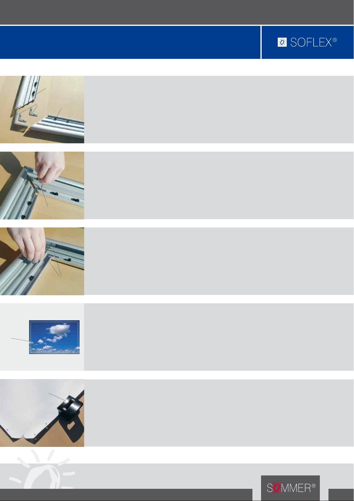
Sichtbarer Spannrahmen
Visible tenter frame
Die soflex®-Spannrahmenprofile werden im 90°-Eckwinkel
an allen vier Ecken zusammengefügt.
Danach werden die Profile mittels dem beiliegenden Im-
busspanner und den 5 mm Madenschrauben fixiert.
Das einzuspannende Aufsichtsmotiv, auf Planenträger
oder Großfoto, muss 100 mm kleiner als das Außenmaß
des soflex®-Spannrahmens sein.
Mit jeweils 20 mm vom Rand beginnend werden mit einem
handelsüblichen Bürolocher umlaufend Löcher zur Aufnah-
me des Spanngummis gestanzt.
Zunächst werden die Befestigungsglieder in die Profilkam-
mer seitenrichtig eingeschoben.
Die Vielzahl der Befestigungsglieder hängt von der Anzahl
der Stanzlöcher ab. Jeweils ein Befestigungsglied weniger
pro Längs- und Querseite als Löcher vorhanden sind.
Formel für die Berechnung der Befestigungsglieder:
Gesamtlänge pro Seite durch 8 dividieren.
The soflex®-tenter frame profiles are connected to all four
corners using a 90° corner joint.
Following this, the profiles are affixed using the socket
head wrench supplied and the 5 mm headless screw.
The display motif that is to be fitted round the frame on the
canvas mount or large-format photo must be 100 mm
smaller than the outer measurements of the soflex®-tenter
frame.
While ensuring that you maintain a distance of 20 mm to
the edges, use a standard hole punch to punch holes all
around the frame to house the tensioning cord.
To begin with, the fastening joints must be inserted into the
correct sides of the profile chamber.
The number of fastening joints depends on how many
holes are available. For each longitudinal and lateral side
should be one fastening joint fewer than holes available.
Formula for calculating the fastening joints: Total length
per side divided by 8.
Spannrahmenprofil
Tenter frame profile
Eckwinkel
Corner joint
Befestigungsglieder
Fastening joints
Imbusspanner
Socket head wrench
Imbus-Madenschraube
Hexagon socket screw
Bürolocher
Hole punch
Aufsichtsmotiv
Reflected motif

Montageanleitung Assembly instruction
6
7
8
9
SOMMER®GmbH · Eisenbahnstraße 20 · D-49176 Hilter
Tel. +49 (0) 54 24 / 22 12 - 0 · Fax +49 (0) 54 24 / 22 12 - 12
E-Mail: info@sommer-gmbh.de · www.sommer-gmbh.de
Sichtbarer Spannrahmen
Visible tenter frame
Spanngummi an allen vier Ecken in die Befestigungsglieder
einhängen!
Die weitere Verspannung beginnt jeweils aus der Mitte der
Längs- und Querseiten, immer gegenüberliegend abwech-
selnd zu den Ecken.
Zwischendurch ist immer darauf zu achten, daß alle vier
Ecken ihre Passgenauigkeit beibehalten.
Beim soflex®-Spannrahmen über 2,5 Metern Länge wird die
mitgelieferte Stützstrebe zentriert montiert.
Markieren Sie den äußeren Rahmen an der Wand in der gewünschten Endposition.
Jeweils an beiden Seiten, vom oberen Bildrand 70 mm vom seitlichen Bildrand ca.
300 mm, die Befestigungslöcher bohren (Abb. 9.1). In gleicher Weise nehmen Sie
den Arbeitsablauf für den unteren Bildrand vor (Abb. 9.2).
Die abgewinkelten Befestigungshaken mit dem Langloch (Abb. 9.2) werden in glei-
cher Weise montiert, müssen jedoch leichtgängig durch ihr Eigengewicht beweglich
bleiben. Der mit dem Motiv bespannte Rahmen wird als erstes in die unteren, mit
dem Langloch versehenden, Befestigungshaken eingesetzt und über die oberen
Haken eingehängt. Durch Ablassen des Rahmens arretiert dieser von selbst.
Die Demontage des Spannrahmens erfolgt durch Anheben und Lösen von den obe-
ren Befestigungshaken.
Trace the outer profile of the frame at the spot on the wall that you ultimately wish
to hang the frame. Drill the mounting holes in line with the back (Fig. 9.1) and en-
sure that, on both sides, they are 70 mm from the upper photo frame and around
300 mm from the side photo frame. Repeat this procedure for the lower photo
frame (Fig. 9.2).
If the angled mounting hooks are mounted with the oblong hole in the same way
(Fig 9.2), ensure that their own weight enables them to be moved at the touch of a
finger. First place the frame complete with the fitted motif onto the lower fastening
hooks so that they latch into the oblong holes and then hang the frame on the up-
per hooks. Lower the frame until it locks in place by itself.
To take down the tenter frame, simply lift and remove it from the upper hooks.
Das Spanngummi auf die gesamte Umlauflänge abmessen und
im Wechsel (oben- und untenliegend) durch die gestanzten Lö-
cher ziehen.
Aufsichtsträger mit Spanngummi leicht auf Vorspannung brin-
gen und mit einem Knoten die beiden Enden verbinden.
Den zusammengeschraubten soflex®-Spannrahmen mit der
Sichtseite nach unten auf eine saubere und kratzfreie Unter-
lage legen. Aufsichtsträger mit der Bildseite nach unten in den
Rahmen einlegen und vermitteln.
Hang the tensioning cord in the fastening joints which are
located in all four corners!
When tightening further, always begin from the centre of
the longitudinal and lateral sides, always alternating bet-
ween opposing corners.
Check every now and then that all four corners maintain
their exact fit.
Where soflex®-tenter frames longer than 2.5 metres are
used, the brace supplied is to be mounted in the middle.
Measure the tensioning cord for the entire length around the
frame and pull it through the punched holes, alternating bet-
ween upper and lower holes as you go.
Slightly tension the reflective base using the tensioning cord
and tie the two ends together in a knot.
Lay the soflex®-tenter frame with the view side downwards
onto a clean and scratch-free surface. Lay on an centralise the
assembled soflex®-tenter frame with the picture-side down-
wards.
Spanngummi in Schlangenform
durchziehen und verknoten.
Pull the tensioning cord through the
holes in a snake-like fashion and tie.
Längs- und Querseite
abwechselnd spannen.
Tension the longitudinal and
lateral sides alternately.
Bestückter
Spannrahmen
Fitted
tenter frame
Wandbefestigung
Wall bracket
Wandhalter, oben
Wall bracket, upper
Wandhalter, unten
Wall bracket, lower
300 mm
300 mm
300 mm
300 mm
70 mm70 mm70 mm70 mm
Spannrahmen, außen
Tenter frame, outer
Abb. 9.1
Fig. 9.1
Spannrahmen, außen
Tenter frame, outer
Abb. 9.1
Fig. 9.1
Popular Indoor Furnishing manuals by other brands


uwis
uwis Caravanbed manual

Lefroy Brooks
Lefroy Brooks M1-5301 Installation, operating, & maintenance instructions

NewAge Products
NewAge Products Bold Series VersaShelf Install instructions

Riverside
Riverside Myra 59453 Assembly instructions

Inval
Inval ES 9303 Assembly Instructions and Warranty

Furniture of America
Furniture of America CM7171Q /F Assembly instructions

Furniture of America
Furniture of America FOA-DK5686 Assembly instructions

BDI
BDI CASCADIA 8254 Assembly instructions

Core Products
Core Products Auckland DL107 manual

Balmani
Balmani Fila Wall Unit installation guide

Classic Exhibits
Classic Exhibits visionary MOD-1294 quick start guide

HYPE
HYPE Kapri quick start guide