SOMMER Maltman 110 User manual
Version: 30.08.2019
Page 1
Operation manual
Maltman 110, Maltman 110 S, Maltman 150, Maltman 150 S,
with 230V or 400V connection
Handbuchart manual
Maschine
Maltma
n
MaschinenTyp
machin
e
Version 1.0
KundeName Egon
Sommer Maschinenbau GmbH &
Co. KG
KundeAdresse
Pagen
stecherstraße 146
KundeOrt D-
49090 Osnabrück
KundeTelefon +49
(0)541 125085
KundeLand
Deutsc
hland
KundeFax +49
(0)541 129557
KundeEmail
service
@sommer-maschinenbau.de
KundeInternet
www.s
ommer-maschinenbau.de
Erstelldatum
30.08.
2019
Dateiname
Zusatz1
Zusatz2
Baujahr 2017
MaschineModell1 Mühle

GENERAL DESCRIPTION
Page 2
Copyright law
This operation manual is a document or instrument in the sense of the Law on Unfair Competition.
The copyright remains with
Egon Sommer Maschinenbau GmbH & Co. KG
Pagenstecherstraße 146
D-49090 Osnabrück
Telefon: +49 (0)541 125085
Telefax: +49 (0)541 129557
E-Mail: service@sommer-maschinenbau.de
Internet: www.sommer-maschinenbau.de
This operation manual is intended for the user/owner of the machine and its staff. It contains texts, pictures and
drawings that, without the express permission of Egon Sommer Maschinenbau GmbH & Co. KG, may not be
reproduced,
disseminated or
disclosed in any other.
Permission is granted for internal use to the user/owner of the machine.
© Copyright Egon Sommer Maschinenbau GmbH & Co. KG 30.08.2019
The manufacturer reserves the right to make technical changes and improvements at any time without prior notice.

GENERAL DESCRIPTION
Page 3
Table of contents
1General description............................................................................................................................ 4
1.1 Information about this Operation manual................................................................................... 4
1.2 Layout of the Operation manual................................................................................................. 4
1.3 Use of the Operation manual ..................................................................................................... 4
1.4 Obligations of the machine owner.............................................................................................. 4
1.5 Personnel requirements............................................................................................................. 5
1.6 Intended use............................................................................................................................... 5
1.7 Unintended use.......................................................................................................................... 5
2Safety instructions ............................................................................................................................. 6
2.1 Safety symbols used in this Operation manual.......................................................................... 6
2.2 Warning labels on the Machine.................................................................................................. 6
2.3 Safety guidelines........................................................................................................................ 7
3Technical data................................................................................................................................... 11
4Setup and function........................................................................................................................... 12
5Safety devices................................................................................................................................... 13
5.1 Shutdown in case of power outage..........................................................................................13
5.2 Protective grid .......................................................................................................................... 13
5.3 Protective cover........................................................................................................................ 13
6Transport/Setting up/Assembly of the Machine............................................................................ 14
6.1 Installation and assembly......................................................................................................... 14
6.1.1 Attaching the Machine ..............................................................................................14
7Initial start-up.................................................................................................................................... 15
7.1 Connecting the power supply................................................................................................... 15
7.1.1 Check for the correct direction of rotation................................................................. 15
8Operation........................................................................................................................................... 15
8.1 Basic checks before and after operations................................................................................15
8.2 Operating elements..................................................................................................................15
8.3 Operating procedure/Crushing cereals.................................................................................... 16
8.3.1 Adjust the feed regulator...........................................................................................16
8.3.2 Adjusting the crushing gap .......................................................................................17
8.3.3 Reduce the crushing gap.......................................................................................... 17
8.3.4 Ejecting foreign bodies ............................................................................................. 17
9Maintenance and care...................................................................................................................... 18
9.1 Maintenance schedule .............................................................................................................18
9.2 Special Maintenance Work ......................................................................................................19
9.2.1 Retightening the V-belt ............................................................................................. 19
9.2.2 Replace the V-belt ....................................................................................................19
10 Malfunction ....................................................................................................................................... 20
10.1 List of malfunctions...................................................................................................................20
11 EC Declaration of Conformity ......................................................................................................... 22

GENERAL DESCRIPTION
Page 4
1General description
This chapter contains notes on this manual, along with general safety instructions for handling the machine of the
Maltman-series.
The Maltman is referred to as the machine in the following.
1.1 Information about this manual
This manual is an integral part of the user documentation for the machine. Observe all instructions, data, and
directives contained in the manual. The manual will help you to operate the manual safely, and with a high level of
availability.
We reserve the right to make changes designed to improve the machine described in the manual at any time
without notice.
1.2 Layout of the manual
Safety-relevant instructions are identified by the appropriate symbols.
Steps that must be performed in the specified order are enumerated and the results of the steps are shown in
italics.
Example:
1. Step 1 to be performed
Result of step 1
2. Step 2 to be performed
2.1 Sub-step of step 2 to be performed
1.3 Use of the manual
The manual is to be supplemented by existing national directives concerning accident prevention and
environmental protection.
Ensure that the manual is always available at the usage site of the machine and in a legible condition.
In addition to the manual and the binding regulations for accident prevention applicable in the country and site of
implementation, the recognised industry-specific rules for safety and professional work must be complied with.
1.4 Obligations of the machine owner
The machine user/owner is obliged to only permit persons to work on the machine , who
Observe the basic directives concerning health and safety at work and accident prevention,
Are regularly instructed in difficulties, hazards, and other particular rules of conduct.
The owner/operator undertakes to:
observe and communicate to staff the current mandatory regulations on accident prevention, environmental
protection and handling of dangerous goods in addition to the instructions in this manual, as required by
law.
provide personal protection equipment.
Establish the authority of the machine operator to enable the machine operator to reject third party
instructions that contradict safety considerations.
assure safety-aware work of personnel at regular intervals.
observe legal requirements and rules at the site of the machine.

GENERAL DESCRIPTION
Page 5
1.5 Personnel requirements
The machine may only be operated by persons of a minimum age of 16 years.
Before commencing work, all persons tasked with working on the machine undertake to:
observe the basic directives concerning health and safety at work and accident prevention,
Read the safety and warning instructions in this manual and to confirm with their signature that they have
understood them,
Use personal/workplace-specific protective clothing and auxiliary materials that serve occupational safety
while working, where these are required from a safety/technical point of view.
comply with specifications of competence.
1.6 Intended use
The machine is used exclusively to process various grain types (such as oats, barley, wheat, maize, spelt, etc.) so
that their form is beneficial for animal feed.
The machine must be operated exclusively within the performance limits stated in chapter 3 "Technical data".
Uses other and beyond this shall be deemed improper and unintended. Egon Sommer Maschinenbau GmbH & Co.
KG will not be held liable for any damage caused by unintended use.
Intended use also includes:
Observing all information and directives in the manual and all accompanying documents.
Observing the mandatory service and maintenance intervals, or the service and maintenance intervals
specified in the manual and applicable documentation.
1.7 Unintended use
Unintended use particularly includes:
Using the machine for purposes other than crushing cereals.
Crushing of materials with a high moisture content/that are very sticky will cause them stick to the rollers of
the crusher (exception:) Use of scrapers).
Operating the machine with bridged safety devices.
Operating the machine with incomplete protection.
Operation of the machine by more than one person.
Operating, maintaining and repairing the machine by non-authorised and non-instructed persons.
Operating the machine in an area with a risk of explosion.
SAFETY INSTRUCTIONS
Page 6
2Safety instructions
2.1 Safety symbols used in this Fehler! Verweisquelle konnte nicht gefunden werden.
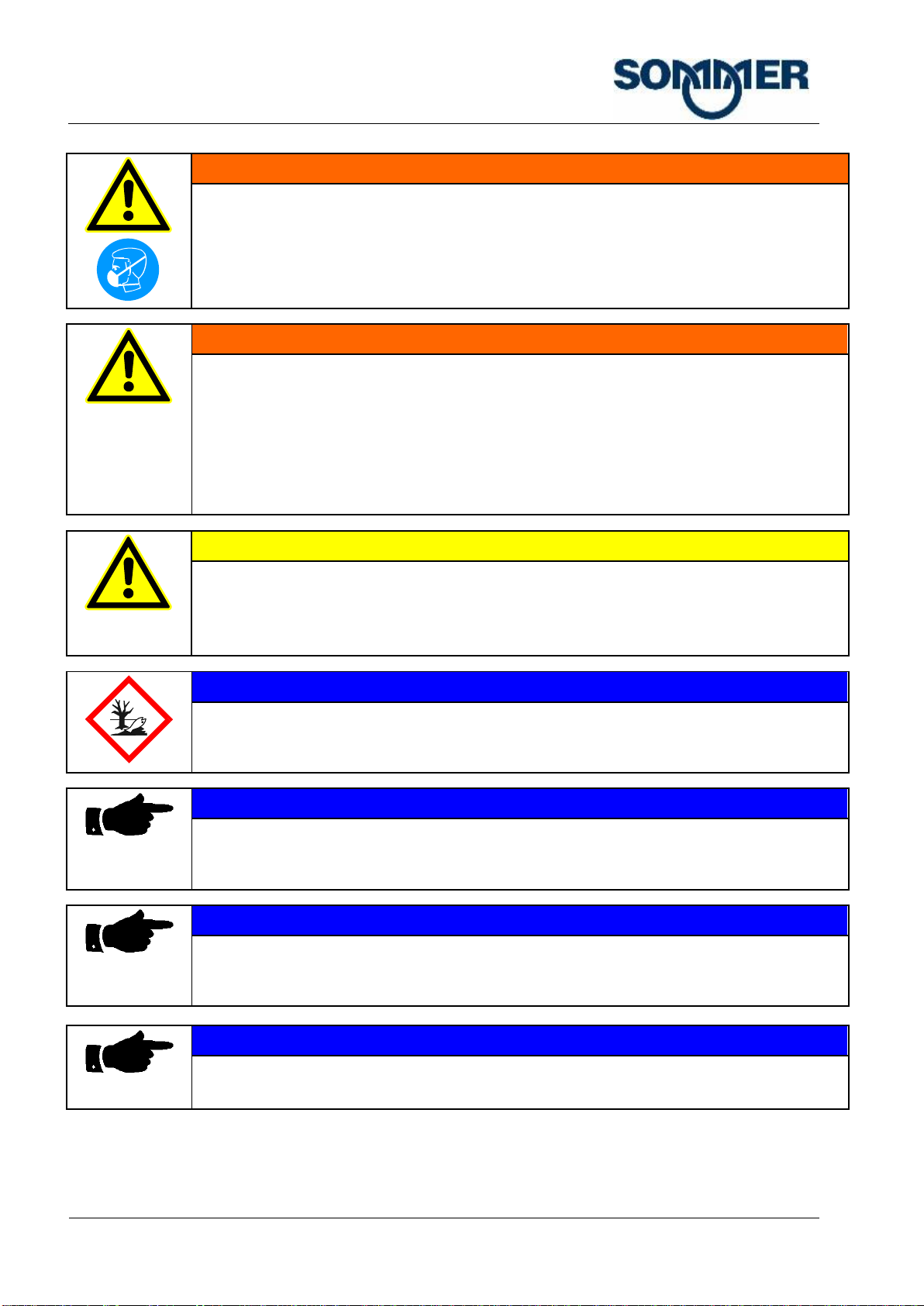
DANGER
"DANGER" identifies an immediate danger which can cause severe or even fatal injury.
WARNING
"WARNING" identifies a potentially dangerous situation which can cause severe or even fatal
injury.
CAUTION
"CAUTION" identifies a potentially dangerous situation which could to minor injury.
NOTE
"NOTICE" identifies a potentially dangerous situation that can harm property and the
environmental.
This signal word is also used for application instructions and other useful information.
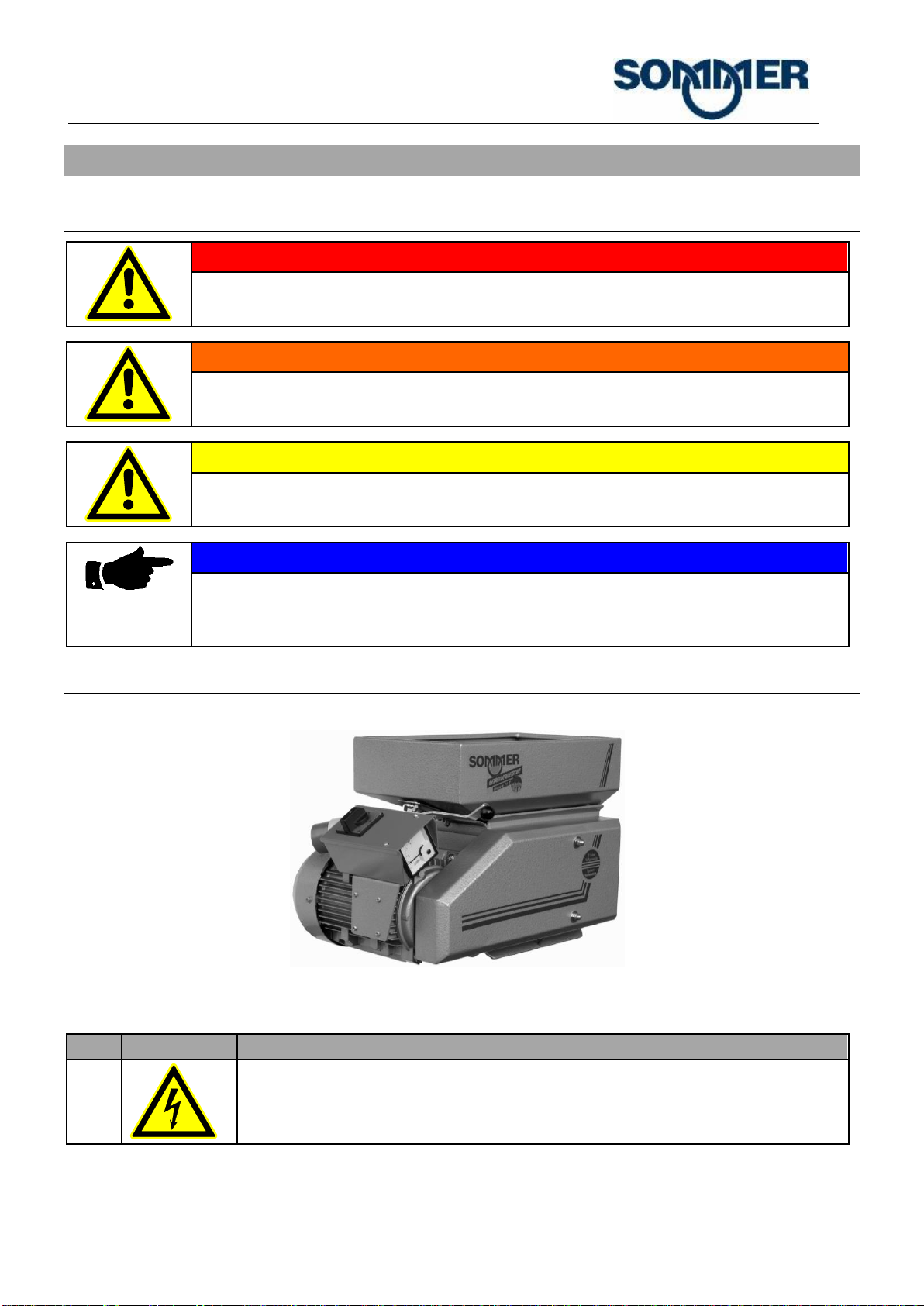
2.2 Warning labels on the machine
Fig. 2-1: Warning labels on the machine
Pos.
Label
Description
1
Warning of hazardous electrical voltage.
SAFETY INSTRUCTIONS
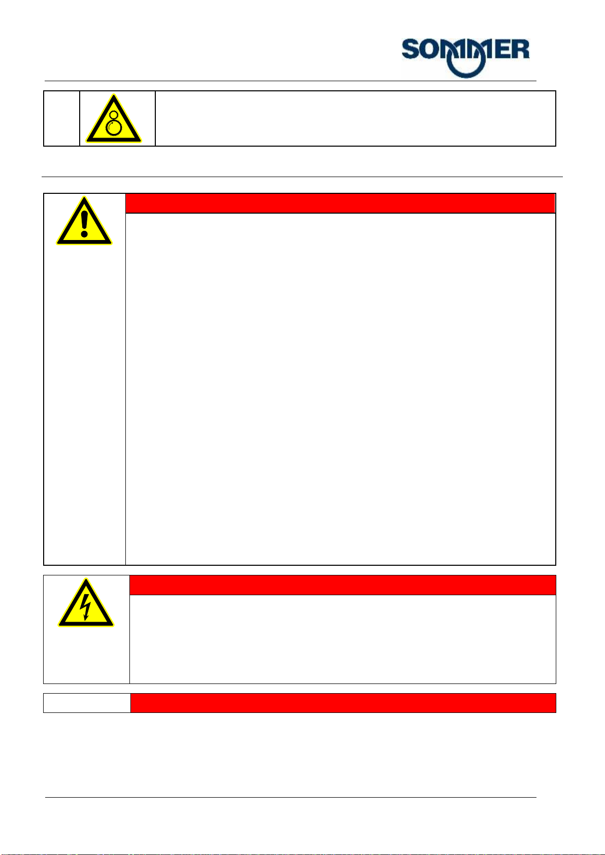
Page 7
2
Risk of drawing in, crushing.
2.3 Safety guidelines
DANGER
Risk to persons and the machine!
Only qualified and authorised persons are permitted to operate the machine.
Only qualified and authorised persons are permitted to operate the machine.
Maintain all safety and hazard instructions at and on the machine in a complete and
legible condition!
Always exercise care and attention in the entire work area of the machine.
Exercise great care when carrying out setup and troubleshooting work requiring the
disabling of safety equipment and/or covers.
Dismantled safety equipment must be refitted after completing the work.
Avoid any unsafe methods of working.
Keep the operating manual available at the machine site at all times.
The machine's operator must have read and understood the Operating Instructions.
Stop the machine immediately and report the fault to the responsible department/person
when safety-relevant modifications are made to the machine line or the operating
behaviour of the machine changes!
Stop the machine immediately and report the fault to the appropriate office/person if
safety-relevant modifications have been made or the operating behaviour of the machine
changes!
The applicable worker's compensation association (BG) rules for Occupational Safety and
Health.
Do not remove or modify safety devices and warning signs from the machine.
Do not convert machine components without our approval.
Access to the workplace on the machine is not permitted for unauthorised persons.
Always exercise care and attention in the entire work area of the machine.
RISKS
Risk of electric shock!
Leave the danger area immediately if electricity leaks to defective components and wiring.
Only have electrical systems installed on machine components by an expert and
according to the wiring diagram.
To protect the machine the power supply must be protected with a residual current circuit
breaker provided by the customer.
RISKS
SAFETY INSTRUCTIONS
Page 8
Danger of injury due to unexpected actuation!
Switch off the machine before setup work, maintenance, repairs and troubleshooting, and
protect against unexpected restarting.
Disconnect the mains plug of the machine.
DANGER
Risk of explosion!
The machine is not explosion-protected as a factory standard. Accumulations of dust can
cause an explosive atmosphere.
Do not use the machine in areas with a potentially explosive atmosphere.
Ensure sufficient ventilation of the room, as crushing causes dust accumulations.
Ensure good ventilation of the machine to avoid an explosive atmosphere building up.
Regularly clean the machine (especially the drive motor) to avoid a layer of dust
accumulating.
DANGER
Risk of fire due to V-belt slipping!
Slipping belts can overheat and cause fires
Make sure the V-belts are tensioned correctly.
Comply with maintenance intervals. First check of V-belt tension after 10-20 hours of
operation, then extend the interval gradually to 3-6 months.
WARNING
Risk of injury due to trapping or pulling in!
Do not wear loose-fitting clothing.
Do not wear ties, necklaces, shawls, scarves or similar.
Tie back long hair (e.g., use a hair net).
WARNING
Risk of crushing, drawing in!
In particular, on the pinch rollers and drive parts (belts and gears, etc.).
Do not reach into rotating/moving machine elements or devices.
Do not reach into the outlet while the machine is running.
WARNING
Parts being ejected!
There may be foreign bodies in the milled material (e.g. ball bearings). During crushing, they
may be propelled upward and out of the hopper with unexpected force by the pinch rollers,
thus causing serious injury.
Do not bend over the feed hopper on the machine during operation.
Remove any foreign bodies that accumulate from the machine (e.g. foreign body ejector).

SAFETY INSTRUCTIONS
Page 9
WARNING
Risk of injury though noise!
Use the mandatory hearing protection.
SAFETY INSTRUCTIONS
Page 10
WARNING
Risk of injury due to dust!
Ensure good supply and exhaust ventilation of the workplace.
Wear the prescribed dust mask/air filter mask if required.
WARNING
Risks of damage to the machine!
Attach the machine at operation height.
Do not firmly attach hopper enlargements (e.g., avoid welding on).
In case of feeding from a silo: Allow the silo outlet to protrude by 1-2 cm into the hopper of
the grain crusher. It must be possible to pull the grain crusher out from below the silo.
When using feed wagons/catchment containers, maintain a short distance to the machine
outlet; otherwise the milled material might drop out next to the catchment container.
CAUTION
Risk of injury during filling
Filling of materials for rolling goods from sacks into the grain crusher may cause back injuries
due to incorrect lifting techniques due to lifting heavy loads.
Pay attention to correct lifting techniques when lifting heavy loads.
NOTE
Pollution!
Dispose of replaced parts, consumables and auxiliary materials in a safe and
environmentally friendly manner.
NOTE
Possible damage due to rain and moisture!
Do not set up the machine outdoors without rain and moisture protection. There is a risk
of very serious damage to the electrical components and bearings.
NOTE
Extended periods of operation in the wrong direction of rotation!
Extended periods of machine operation in the wrong direction of rotation, especially under
load (milling materials on the rollers) can cause damage to the machine.
NOTE
Use only original spare parts.
Only use materials and original spare parts recommended by the manufacturer.

TECHNICAL DATA
Page 11
3Technical data
Machine
Malt mill
Malt mill
Type
Maltman 110 & 150
With 230V or 400V
Maltman 110 S & 150 S
With 230V or 400V
Grain throughput [kg/h]
(depending on the degree of
crushing and type and humidity
of the
material to be crushed)
approx. 300 –400
approx. 150-200
Motor output [kW]
1,1
1,5
Electrical connection
230V, single phase or 400 V,
3-phase
230V, single phase or
400 V, 3-phase
Weight [kg]
62
77
Dimensions [cm] (W x H x D)
58 x 40 x 33
58 x 40 x 33
Degree of protection
IP 54
IP 54
Emission sound pressure level
at idle speed [dB(A)]
70,2
70,2
Permissible materials for
processing
Grain (such as malt oats,
barley, etc.)
See before
Crushing gap [mm]
0 –2.6
0 –2,6
SETUP AND FUNCTION
Page 12
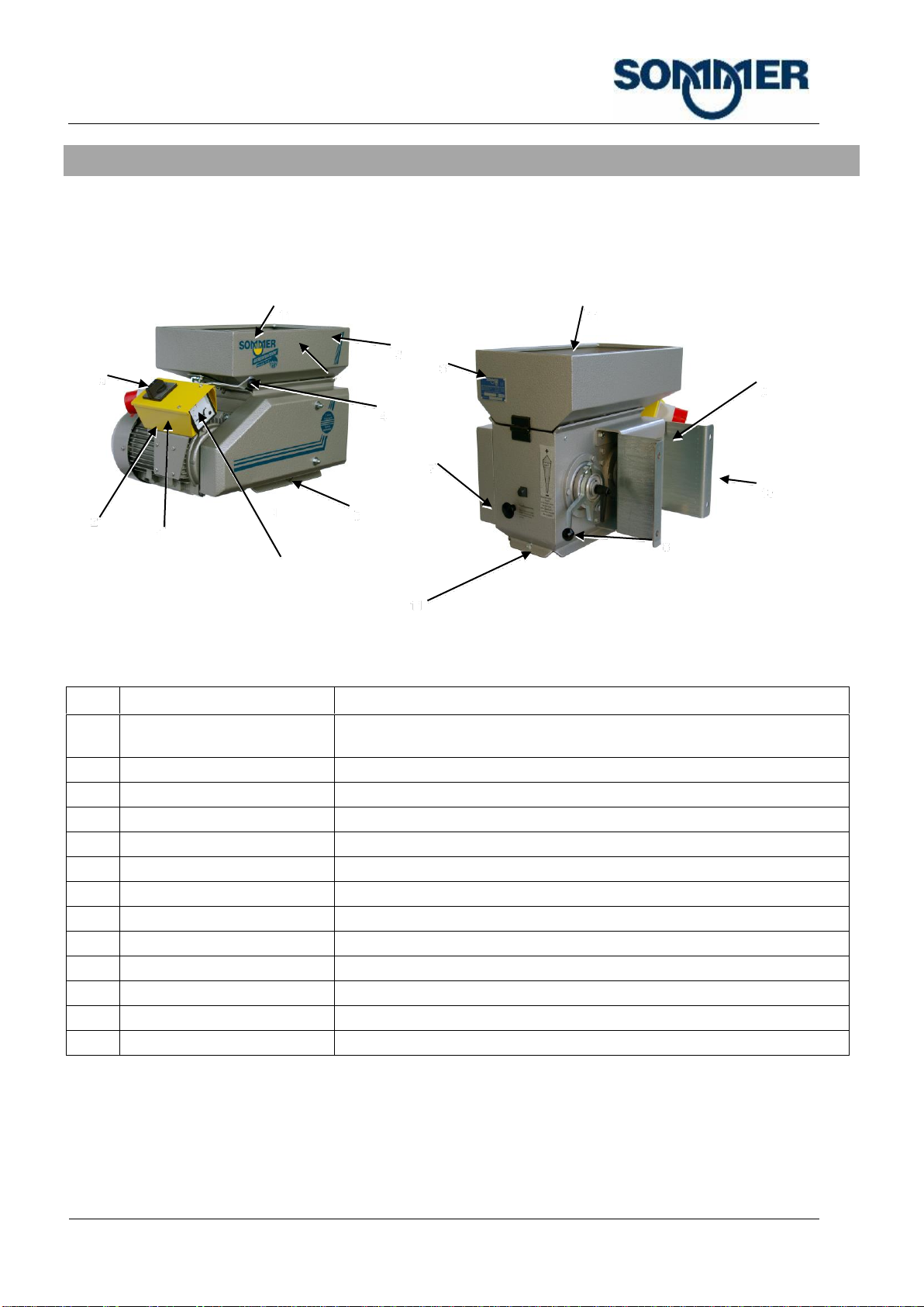
4Setup and function
The machine crushes various cereals (oats, barley, wheat, corn, spelt, etc.). The operator fills the material to be
crushed into the feed hopper (3). From there, it flows in a metered manner onto the two powered pinch rollers
which crush the material between them. The crushing force depends on the size of the material to be crushed
relative to the gap set between the pinch rollers. The crushed end product drops out of the outlet opening on the
underside of the machine.
Pos.
Description
Function
1
Electronics cabinet
Houses the main switch with motor protection switch, ammeter with load
and overload indicator and plug.
2
Drive motor
Drives the machine
3
Hopper
Receives the material to be crushed and feeds it to the pinch rollers.
4
Feed control
Sets the feed gap in the hopper.
5
Outlet angle bracket frame
Holds the catchment sacks. Outlet for crushed grain.
6
Type plate
Shows the machine data.
7
Foreign body ejector
Removes foreign bodies from the pinch rollers.
8
Crushing gap adjustment
Sets the width of the crushing gap between the pinch rollers.
9
Suspension brackets
Attach the machine to the holder (wall hanger bracket, stand).
10
Wall hanger bracket
Holds the machine
11*
Protective grille
Protects against reaching in.
a
Main switch
Switches the machine on/off
b
Ammeter
Shows the machine load.
*Not shown in the figure.
5
1
2
4
3
6
7
8
9
10
a
b
11
11
11
11

SAFETY DEVICES
Page 13
5Safety devices
5.1 Shutdown in case of power outage
If the power supply is lost by a fuse being tripped, the on/off switch of the machine assumes the off position. This
ensures that the machine will not automatically restart when the power supply is restored. The machine must be
switched on again by pressing the button.
The machine can only be switched on when the machine is connected to a power supply.
5.2 Protective grid
Protective grilles are located:
In the hopper as reach-in protection above the feed to the pinch rollers.
Above the discharge side to prevent reaching into the pinch rollers from underneath.
The protective grilles are removable with tools to facilitate cleaning and maintenance. The protective grilles must be
bolted on for operation with the machine.
5.3 Protective cover
Protective covers are located:
Above the belt drive,
Above the gearbox on the pinch rollers
Above the fan on the drive motor
The protective covers are removable with tools to facilitate cleaning and maintenance. The protective covers must
be in place during operation.

TRANSPORT/SETTING UP/ASSEMBLY OF THE
MACHINE
Page 14
6Transport/Setting up/Assembly of the machine
6.1 Installation and assembly
6.1.1 Attaching the machine
Fig. 6-1: machine Attaching to the head plate of the stand
Requirements:
NOTE
Installation of the wall hanger bracket
The wall must be able to accommodate the weight of the machine permanently (see
section 3 "Technical data").
The wall hanger bracket is mounted or there is a gantry stand (optional).
The machine is switched off
The machine is not connected to the power supply.
Steps:
1. Attach the machine via its rear bracket to the wall hanger bracket or the head plate of the stand.

INITIAL START-UP
Page 15
7Initial start-up
7.1 Connecting the power supply
Requirements:
The machine is mounted on the wall/a gantry stand.
Steps:
1. Connect the machine to the wall outlet with the 16 A-CEE device connector using an extension cable with
phase shifter.
7.1.1 Check for the correct direction of rotation
Requirements:
The machine is connected to a power outlet.
Steps:
1. Switch on the machine and then switch off again immediately.
2. Watch the fan blades through the motor ventilation grille.
An arrow above the ventilation grille indicates the correct direction of rotation.
3. In case of an incorrect direction of rotation, rotate the phase inverter in the extension cable through two
phases (no electrician required).
8Operation
The machine must only be deployed for its intended use (see Section 1.6 "Intended use").
The machine is operated in manual mode.
8.1 Basic checks before and after operations
Familiarise yourself with your workplace before starting work. You must check the machine for signs of visible
defects at least once a day (visual check). The intervals for inspection and maintenance work as found in section 9
"Maintenance and care" must be observed.
Before switching on the machine and during operation, monitor the whole machine constantly for irregularities. The
following features may indicate irregularities when the control system and the machine are switched on:
increased noise, noise occurring at irregular intervals/unusual noises.
Unusual smells.
Smoke development.
Diminished performance during operation.
Immobilise the machine immediately upon the first signs of any of the above issues. Inform the person responsible
immediately in order to evaluate the technical status. If a failure is anticipated due to the damage, perform repairs
without delay.
8.2 Operating elements
The Operating elements are described in section 4 "Setup and function".

OPERATION
Page 16
8.3 Operating procedure/Crushing cereals
Requirements:
The machine is connected to the power supply.
The machine is switched off
The inlet gate is fully closed.
There is no milling material on the pinch rollers.
Steps:
NOTE
Stationary pinch rollers!
There must be no milling material on or between the pinch rollers while the rollers are
stationary. Always close the feed gate first, and then fill the funnel with milling material.
1. Fill the milling material into the hopper or silo feeder.
2. Attach a catchment sack at the machine discharge or a catchment container below machine.
3. Switch on the machine at the main switch.
Allow the pinch rollers to accelerate to final speed.
4. Open the feed gate.
Grain runs onto the pinch rollers and is crushed.
NOTE
machine overload. Red zone on ammeter!
The red zone indicates a motor overload. Avoid permanent overload of the motor. It is not a
problem if the pointer briefly deflects into the red zone.
5. Close the feed gate and allow the rollers to run empty.
6. Switch off the machine at the main switch.
8.3.1 Adjust the feed regulator
Increasing and reducing the milling material feed:
1. Push the wheel of the feed regulator towars the machine
OPERATION
Page 17
8.3.2 Adjusting the crushing gap
Adjust the gap to match the desired results and the size of the material to be crushed.
NOTE
Damage caused by tools!
Only adjust the crushing gap manually. The use of tools can cause damage to the
adjustment gear.
Requirements:
The machine is switched off
The feed gate is closed.
There is no milling material on the pinch rollers.
Steps:
1. Adjust the crushing gap; to do so:
1.1. Loosen the clamping lever on the back of the machine and turn the adjusting lever
8.3.3 Reduce the crushing gap
NOTE
Damage caused by accumulations of milling material!
Clogging of the outlet (e.g., due to backlogs) can result in damage to the machine.
Replace catchment sacks or catchment containers regularly with empty ones.
Verify that
The rolled material can drop freely downwards out of the machine.
The rolled material does not accumulate up to the bottom edge of the machine outlet.
8.3.4 Ejecting foreign bodies
Remove foreign bodies (e.g., small stones) from the pinch rollers.
Requirements:
The machine is running.
Steps:
1. Pull the handle on the foreign body ejector while the machine is running.
MAINTENANCE AND CARE
Page 18
9Maintenance and care
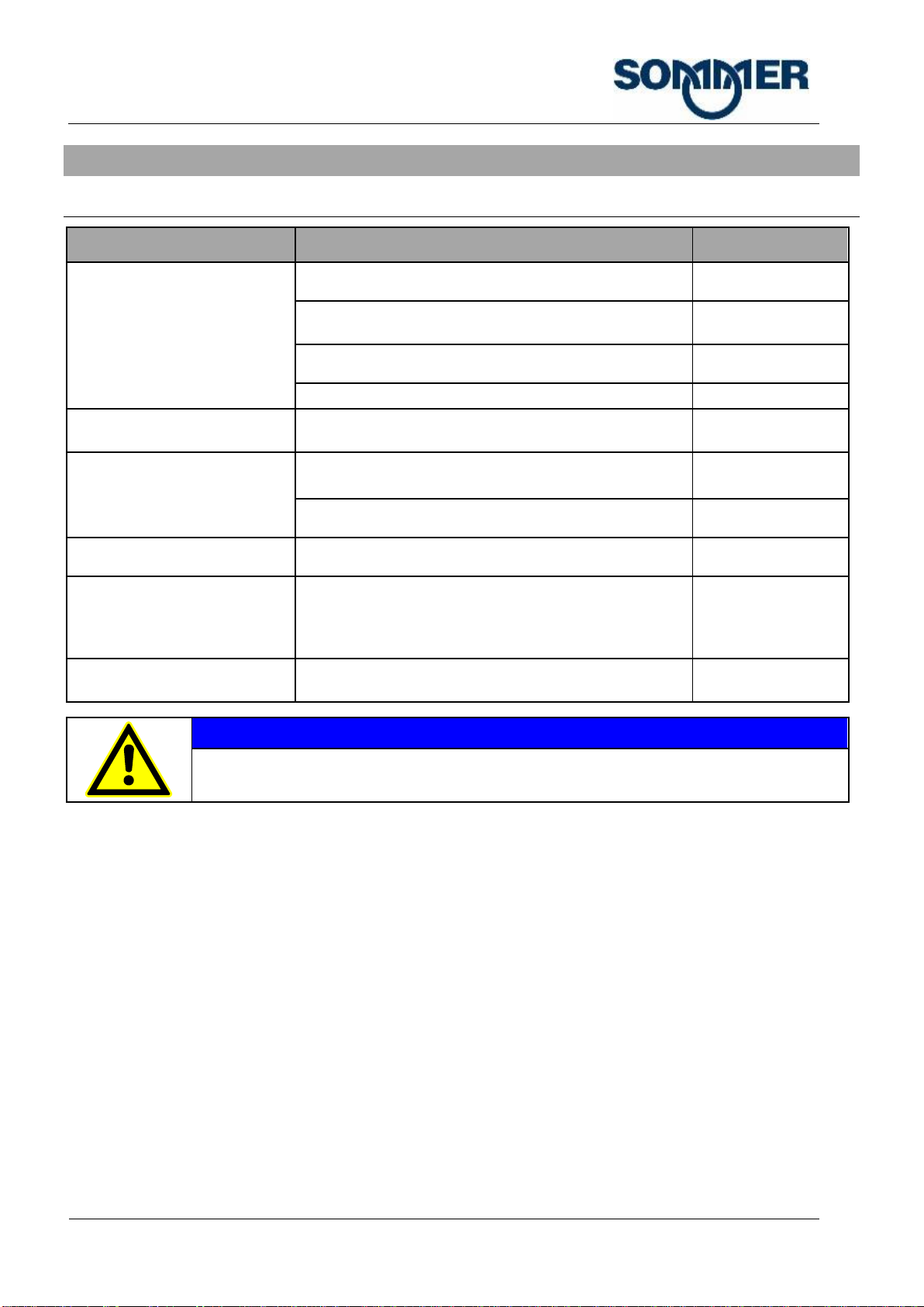
9.1 Maintenance schedule
Machine part
Work to be performed
Interval
Overall machine
Check the on/off switch function
In every shift
Check for orderly condition and cleanliness of the
machine. If necessary, clean the machine.
In every shift
Check function.
In every shift
Check all screws and tighten as needed.
Weekly
Electrical equipment
Check the electrical equipment. Replace damaged
switches/cables immediately.
Every six months/
as needed
V-belt
Check the tension, retension.
Initally after 10-20 h
Every 3-6 months
Check for damage/wear.
Every 3-6 months
Pinch rollers
Remove foreign bodies from the pinch rollers.
As required
Hopper/run-in grille/magnets
Remove foreign bodies (e.g. straw).
Remove metal objects from the magnets.
As required
Depends greatly on
the material to be
crushed.
Protective grilles and safety
covers
Clean grilles.
As required
NOTE
Do not clean with running water!
Do not clean the machine with running water (e.g., water hose, pressure cleaner).
MAINTENANCE AND CARE
Page 19
9.2 Special Maintenance Work
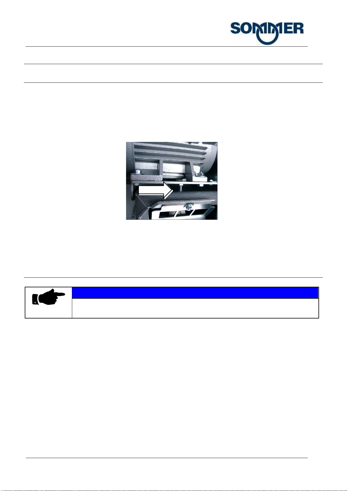
9.2.1 Retightening the V-belt
Requirements:
The machine is switched off
The machine is disconnected from power supply (unplugged).
Steps:
1. Remove the V-belt guard.
Fig. 9-1: V-belt tensioning screw between motor plate and machine housing
2. To tension the V-belt loosen the clamping screw between motor plate and machine housing. Tension the
V-belt until the back of the belt begins to bulge inward on the motor side pulley.
3. Fit the V-belt guard.
9.2.2 Replace the V-belt
NOTE
Always replace the complete V-belt set!
If one V-belt needs to be changed, always replace the complete V-belt set.
Requirements:
The machine is switched off
The machine is disconnected from power supply (mains plug is unplugged).
Steps:
1. Remove the V-belt guard.
2. Tighten the tensioning screw between motor plate and machine housing
V-belts are relaxed.
3. Remove worn V belt.
4. Fit new V belts individually.
4.1 Lay the V-belt over the outside groove on the small, motor-side pulley.
4.2 Pull the V-belt over the outside groove on the large pulley.
4.3 Push the V-belt towards the inside groove by groove.

MALFUNCTION
Page 20
4.4 Identical procedure for remaining V-belts.
10 Malfunction
10.1 List of malfunctions
Symptoms
Cause
Measure
Poor machine
performance/grain not being
processed
Rollers blocked
See section 8.3.2 "Adjusting the
crushing gap"
V-belt loose, warn or defective.
See section 9.2.1 "Retightening the V-
belt" or section 9.2.2 "Replace the V-
belt".
Incorrect roller travel direction.
See section 7.1 "Connecting the power
supply"
Clogged hopper, foreign bodies
on the rollers.
Remove foreign bodies from intake,
protective grilles or rollers.
Rollers worn.
Contact the manufacturer.
Poor motor performance:
Running on 2 phases
Call in an electrician
machine with a substantial
performance drop
Clogged hopper, foreign bodies
on the rollers.
Remove foreign bodies from intake,
protective grilles or rollers.
Poor motor performance:
Running on 2 phases
Call in an electrician
Rollers not running in sync.
Contact the manufacturer.
Rollers worn.
Contact the manufacturer.
machine only partially
crushing the material
Worn partition panels.
Fit new partition panels (see Fig. 10-1:
Partition panels on the face sides of
the pinch rollers).
Foreign body ejector is
jammed/defective
Remove foreign body preventing the
flap from closing.
Rollers worn.
Contact the manufacturer.
Rollers not running in sync.
Contact the manufacturer.
machine not crushing the
material at all
Incorrect roller travel direction.
See section 7.1 "Connecting the power
supply"
machine smells of burning
rubber
V-belt loose, warn or defective.
See section 9.2.1 "Retightening the V-
belt" or section 9.2.2 "Replace the V-
belt".
Motor humming, ammeter
fully deflected at idle speed
Poor motor performance:
Running on 2 phases
Call in an electrician
This manual suits for next models
3
Table of contents
Popular Kitchen Appliance manuals by other brands


Jenn-Air
Jenn-Air BEVERAGE CENTER Use & care guide

Cloer
Cloer 6235 instruction manual

Gorenje
Gorenje HBX602RLBK Instructions for use

Brouwland
Brouwland Transfermer 017.140.5 manual

LINDR
LINDR Green Line PYGMY PRO KITCHEN instruction manual

Nostalgia Electrics
Nostalgia Electrics CARNIVAL CCM-Series instructions