First Choice E Series Guide

SPARE PARTS DIAGRAM FOR
First Choice Group
Blakeney Way, Kingswood Lakeside
Cannock, Staffs, WS11 8LD
TEL: 01543 577778 FAX: 01543504141
Email: [email protected]
Web: www.firstchoice-cs.co.uk
Pizza Oven
E44 /E66 / E66-60 / E99

ENGLISH
INSTRUCTIONS FOR USE AND MAINTENANCE
ELECTRIC OVENS FOR PIZZA
SERIES “E”
Via delle Industrie 90, - 31030 Dosson di Casier (Tv) Italy - Tel. + 39 0422 634202 Fax +39 0422 634205

DECLARATION OF CE CONFORMITY
Declares that the oven
Complies with the requirements of the Directives:
“Low Voltage Directive” 2006/95/EEC
(Of the Council, dated 12 December 2006, on the approximation of the laws of the member States relating to electrical equipment destined to be
used within given voltage limits)
“Electromagnetic Compatibility Directive” 2004/108/EEC
(on the approximation of the laws of the member States relating to electromagnetic compatibility)
and it further declares that the following harmonized standards have been applied:
EN ISO 12100-1-2: 2005
(Basic concepts for the safety of the machines and main principles for design)
EN 60204-1: 2006
(Safety of machinery. Electric equipment of the machines)
Surname and Name:
...
GIACOMINI ERNESTO..…………
Date:
………….
/
………….
/
………….
Stamp and Signature:

5
Instructions for use and maintenance
Rev. 11/2013 - EN
INDEX
INDEX
...................................................................................................................................................p. 4
1- “CE” DECLARATION OF CONFORMITY AND MARKING
1.1- Declaration of “CE” conformity.......................................................................................p. 3
1.2- “CE” marking..................................................................................................................p. 5
2- GENERAL REMARKS
2.1- The importance of the manual.......................................................................................p. 5
2.2- Status of “turned off oven” ............................................................................................p. 6
2.3- Warranty ........................................................................................................................p. 6
2.4- Reserved rights .............................................................................................................p. 6
3- TECHNICAL DESCRIPTION
3.1- Denomination of the components .................................................................................p. 6
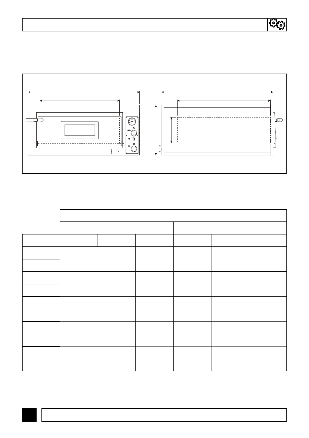
3.2- Dimensions of oven and baking chamber .....................................................................p. 6
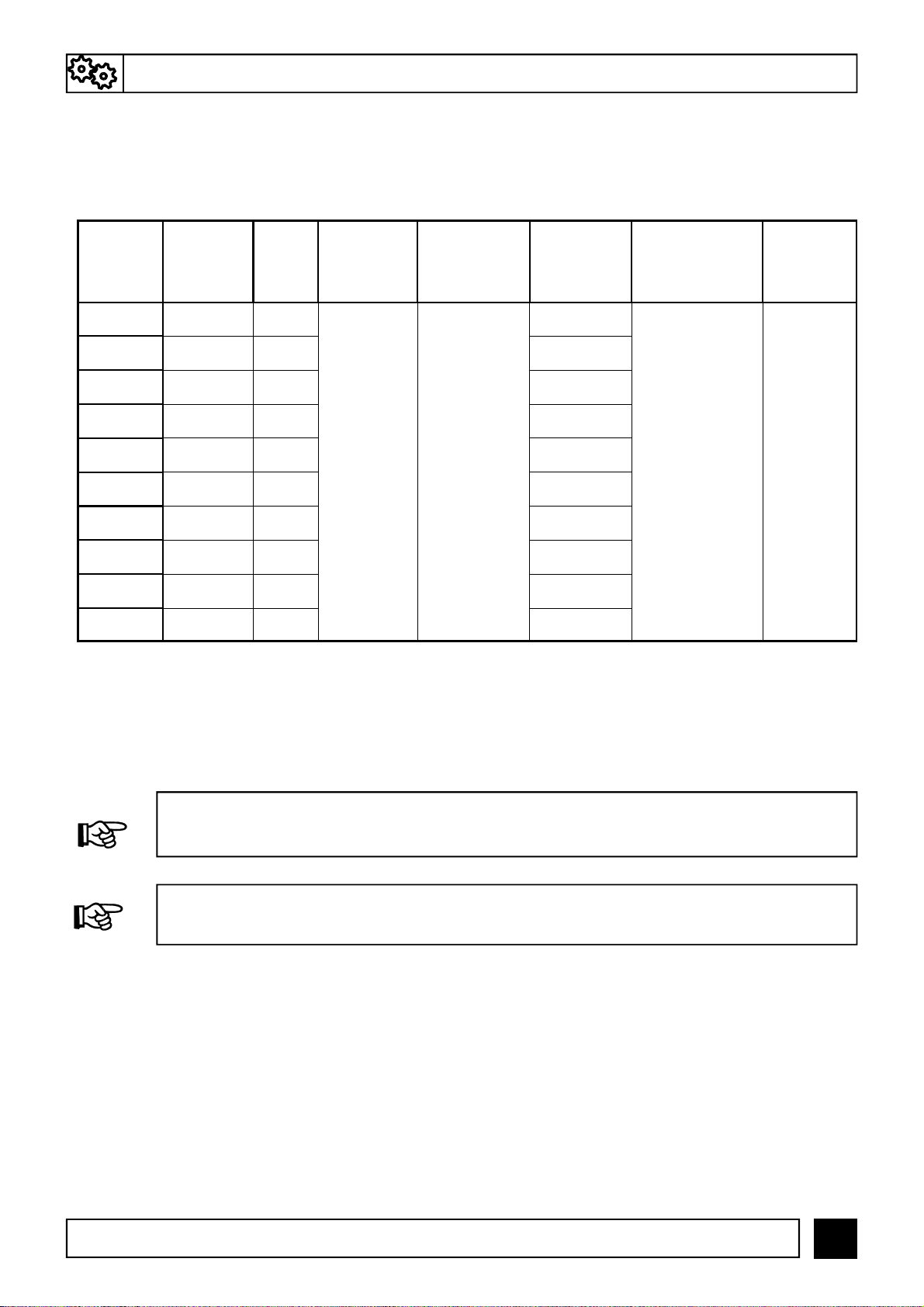
3.3- Technical data................................................................................................................p. 8
3.4- Destination of use..........................................................................................................p. 8
3.5- Limits of use...................................................................................................................p. 8
4- HANDLING AND TRANSPORT
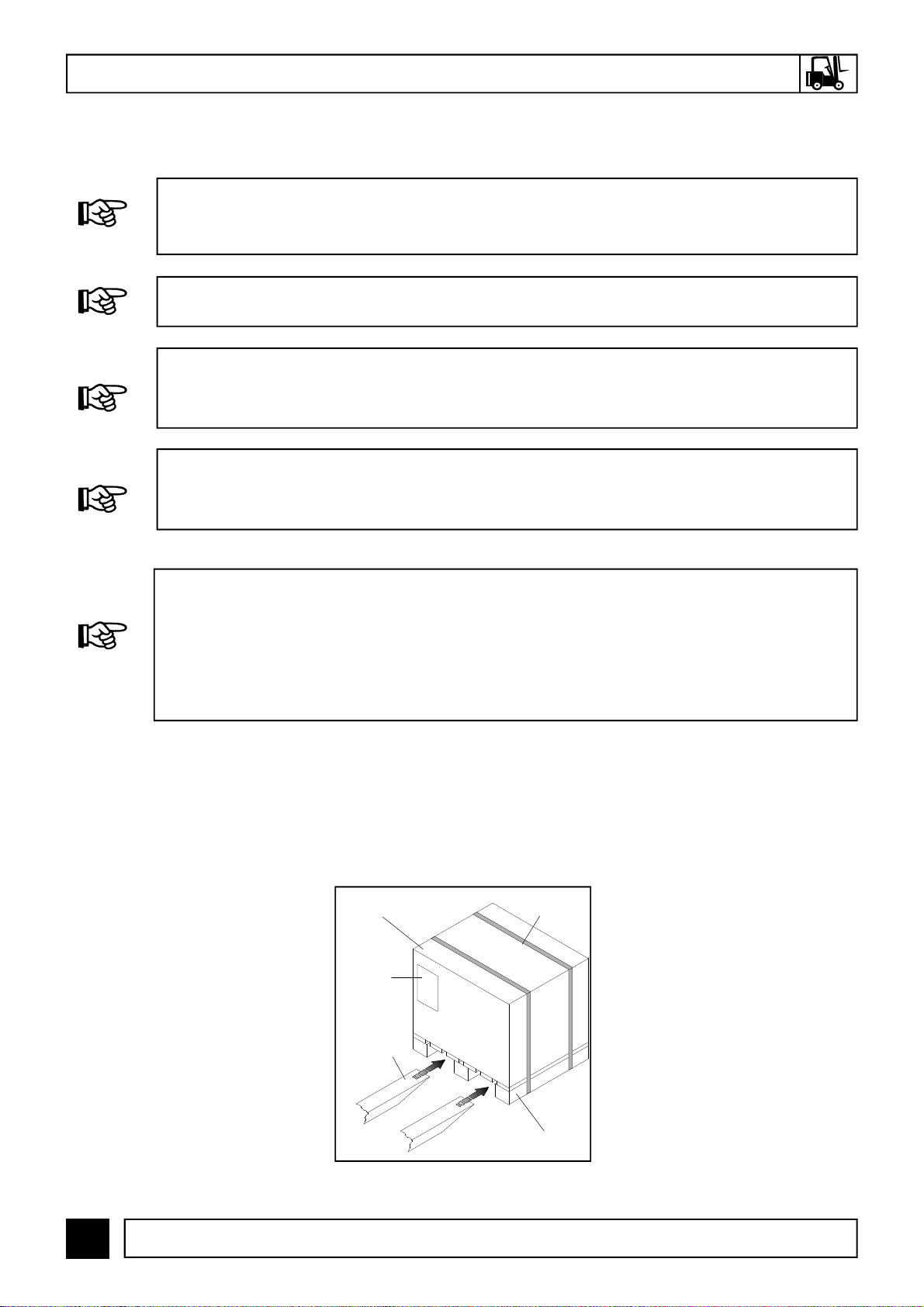
4.1- Transport and lifting.......................................................................................................p. 9
4.2- Instruction sheet applied on the package....................................................................p. 10
4.3- Positioning ...................................................................................................................p. 10
5- INSTALLATION
5.1- Connection to the stack...............................................................................................p. 10
5.2- Electric connection.......................................................................................................p. 11
6- SAFETY
6.1- Reference directives and standards............................................................................p. 12
6.2- Personal protective equipment (PPE)..........................................................................p. 12
6.3- Residual risks...............................................................................................................p. 12
7- USE AND OPERATION
7.1- Control panel................................................................................................................p. 13
7.2- First commissioning.....................................................................................................p. 14
7.3- Turning on of the oven.................................................................................................p. 14
7.4- Turning off of the oven.................................................................................................p. 15
8- MAINTENANCE
8.1- Routine maintenance...................................................................................................p. 15
8.2- Supplementary maintenance.......................................................................................p. 15
9- DEMOLITION
9.1- General warnings.........................................................................................................p. 16
10- SPARE PARTS
Warnings.............................................................................................................................p. 16
Tables and drawings of spare parts....................................................................................p. 17
11- ELECTRIC EQUIPMENT
Wiring diagrams and list of components.............................................................................p. 26
12- ENCLOSURES
12.1- Lifting instruction sheet applied on the package.......................................................p. 33

6
Instructions for use and maintenance
Rev. 11/2013 - EN
1.2- “CE” MARKING
The CE marking is a printed label (black color) applied as shown in FIG. 1. The plate bears in readable
and indelible way the following data:
- Name of the manufacturer; - Serial number (MATR);
- CE marking; - Electric voltage and frequency (Volt/Hz);
- Model (MOD); - Year of construction (ANNO);
- Electric power (kW/A); - Weight of the oven (PESO);
- “Made in Italy”
MARKING
FIG.1
(CE-marking)
ELECTRIC OVENS FOR PIZZA
SERIES “E”
GENERAL REMARKS -2
2.1– THE IMPORTANCE OF THE MANUAL
BEFORE USING THE CONCERNED OVEN, IT IS COMPULSORY TO READ AND UNDERSTAND
THIS MANUAL IN ALL ITS PARTS.
THIS MANUAL IS AN INTEGRAL PART OF THE OVEN AND MUST BE PRESERVED UNTIL ITS
FINAL DISMANTLING.
THE MANUFACTURER DECLINES ALL LIABILITY FOR EVENTUAL DAMAGES TO PERSONS,
ANIMALS, AND THINGS CAUSED BY THE INOBSERVANCE OF THE REGULATIONS DE-
SCRIBED IN THIS MANUAL.
THIS MANUAL MUST ALWAYS BE AVAILABLE FOR THE “AUTHORIZED OPERATORS” AND
HAS TO BE PLACED AND PRESERVED CLOSE TO THE OVEN.
THE “AUTHORIZED OPERATORS” MUST PERFORM ON THE OVEN EXCLUSIVELY INTERVEN-
TIONS FOR WHICH THEY ARE SPECIFICALLY COMPETENT.

7
Instructions for use and maintenance
Rev. 11/2013 - EN
3.1 DENOMINATION OF THE COMPONENTS
FIG. 2 shows and contains the denominations of the components making up the oven.
3.2– DIMENSIONS OF OVEN AND BAKING CHAMBER
ELECTRIC OVENS FOR PIZZA
SERIES “E”
FIG.2
(Denomination of the components)
LEGEND:
1) Oven door handle
2) Steam discharge
3) Chamber light
4) Power supply cable
(without plug)
5) Aeration openings
6) Control panel
7) CE marking
8) Inspection glass
9) Oven door
69 8 5
2
7
1
4
3
2.2- STATUS OF “TURNED OFF OVEN”
Before performing any type of maintenance and/or adjustment intervention, it is compulsory to
disconnect the power supply source, disconnecting the power supply plug from the mains outlet
verifying that the oven is effectively turned off and cooled.
2.3- WARRANTY
The manufacturer warrants that the concerned ovens are tested at manufacturer’s premises.
The warranty of the oven is of 12 (twelve) months.
2.4- RESERVED RIGHTS
The reserved rights concerning this technical manual, “Use and maintenance instructions” remain
property of the Manufacturer. No part of the manual can be reproduced and disclosed by any
reproduction means without prior written authorization of the Manufacturer.
All quoted trademarks belong to the related owners.
2– GENERAL REMARKS
THE TAMPERING AND/OR REPLACEMENT OF PARTS WITH NON ORIGINAL SPARE PARTS
CAUSE THE DECAY OF THE WARRANTY AND RELEASE THE MANUFACTURER FROM ANY
LIABILITY.
3– TECHNICAL DESCRIPTION

8
Instructions for use and maintenance
Rev. 11/2013 - EN
FIG.3
(Dimensions of the oven and of the baking chamber)
Left side
D
Front side
A B
C
FIG. 3 and TAB. 1, in the related views, give the overall dimensions of the oven and of the baking
chamber.
E
F
DIMENSIONS (mm)
EXTERNAL BAKING CHAMBER
MODELS A B C D E F
MICRO 555 460 290 405 405 110
MINI 780 600 530 500 510 110
E4 900 735 420 610 610 140
E44 900 735 750 610 610 140
E6 900 1020 420 610 915 140
E66 900 1020 750 610 915 140
E6/60 1150 735 420 910 610 140
E66/60 1150 735 750 910 610 140
E9 1150 1020 420 910 910 140
E99 1150 1020 750 910 910 140
TAB.1
(Dimensions of the oven)
TECHNICAL DESCRIPTION -3

9
Instructions for use and maintenance
Rev. 11/2013 - EN
FORESEEN USE: PIZZA BAKING, GRATINATING OF GASTRONOMY PRODUCTS AND HEAT-
ING OF FOODSTUFFS IN BAKING PANS.
TAB.2
(Technical data)
3.3- TECHNICAL DATA
TAB. 2 gives the technical data characterizing the different oven models.
3.5- LIMITS OF USE
This oven has been designed and manufactured exclusively for the destination of use described
in
Par. 3.4
, therefore, any other type of use is strictly forbidden in order to assure, at any time, the
safety of the authorized operators, as well as the efficiency of the oven itself.
MODELS BAKING
CHAMBER
(q.ty)
WEIGH
T
(kg)
ELECTRIC
VOLTAGE
(V)
ELECTRIC
FREQUENCY
(Hz)
ELECTRIC
POWER
(kW)
OPERATING
TEMPERATURE
(°C)
BAKING
SURFACE
(material)
MICRO 1 27
50/60
2,2
50 ÷ 500 Refractory
stone
MINI 2 78,5 6
E4 1 93 4,2
E44 2 163 8,4
E6 1 126 7,2
E66 2 218 14,4
E6/60 1 130 6,4
E66/60 2 230 12,8
E9 2 175 9,6
E99 2 320 19,2
200/230/400
THE OVEN CAN BE USED EXCLUSIVELY BY AN AUTHORIZED OPERATOR (USER).
3.4- DESTINATION OF USE
The foreseen use for which this oven has been designed and produced is the following one:
3– TECHNICAL DESCRIPTION

1
Instructions for use and maintenance
Rev. 11/2013 - EN
HANDLING AND TRANSPORT
To ease the transport and the loading and unloading procedures, the oven is packed in a cardboard
box on a wooden basement of pallet type and it is fastened using straps. Moreover, the oven is coated
by a transparent nylon coating. Once the transport and lifting procedures have been performed and
after having located the oven in the proper working position, unpack the oven by cutting the straps, the
cardboard box and the nylon coating.
FIG.4
(Insertion of the lift truck forks)
Straps
Box
Lift truck
forks
Pallet
Warning
label
DURING THE LIFTING AND HANDLING PROCEDURES OF THE OVEN, MAKE SURE THAT
WITHIN THE RANGE OF ACTION THERE ARE NOT PERSONS, ANIMALS OR THINGS WHOSE
SAFETY MAY BE ACCIDENTALLY ENDANGERED.
COMPULSORY USE LIFTING AND HANDLING MEANS AND SYSTEMS SUITABLE AND
PROPER FOR THE WEIGHT AND THE SIZE OF THE OVEN (SEE PAR. 3.2 - 3.3).
SHOULD A FORK LIFT TRUCK BE USED TO PERFORM THE LIFTING AND HANDLING
PROCEDURE, MAKE SURE TO POSITION THE FORKS PROPERLY AVOIDING ABSOLUTELY
TO BUMP INTO THE LOAD (FIG. 4).
DURING THE LIFTING AND HANDLING OF THE OVEN, IT IS STRICTLY FORBIDDEN TO
PERFORM SUDDEN BRAKINGS, ACCELERATIONS AND/OR SUDDEN DIRECTION CHANGES.
4.1- TRANSPORT AND LIFTING
UPON DELIVERY CHECK THAT THE OVEN HAS NOT UNDERGONE DAMAGES DURING
TRANSPORT. SHOULD THIS BE THE CASE, INFORM THE CARRIER OF THE DAMAGE
IMMEDIATELY BY WRITING A NOTE ON THE TRANSPORT DOCUMENT. MOREOVER, VERIFY
THAT THE ACCESSORIES SUPPLIED, AS WELL AS EVENTUAL OPTIONAL ITEMS REQUIRED
HAVE ALL BEEN DELIVERED. ANY EVENTUAL COMPLAINT MUST BE SUBMITTED IN
WRITING BY YOUR DEALER TO THE MANUFACTURER BY AND NOT LATER THAN 8 (EIGHT)
DAYS.

11
Instructions for use and maintenance
Rev. 11/2013 - EN
4– HANDLING AND TRANSPORT
4.2- INSTRUCTION SHEET APPLIED ON THE PACKAGE
Externally on the package, it is applied an instruction sheet for the handling of the same.
(See Chap. 12 - ENCLOSURES).
4.3- POSITIONING
The positioning of the oven must be performed observing the minimum dimensions (mm) quoted in
FIG. 5. It must lean on a suitable support surface capable to sustain its weight and heat.
It is suggested to leave the right side of the oven free, in order to ease the disassembling of the
covering panel in case of maintenance.
Stack
5 cm 5 cm
5 cm
5 cm
Right side Front side
FIG.5
(Positioning)
ALL OVEN INSTALLATION PROCEDURES (POSITIONING AND ELECTRIC CONNECTION)
MUST BE PERFORMED COMPULSORILY AND EXCLUSIVELY BY AUTHORIZED PERSONNEL
SATISFYING THE TECHNICAL AND PROFESSIONALS REQUIREMENTS STATED, IN FULL
COMPLIANCE WITH THE REGULATIONS IN FORCE IN THE COUNTRY OF USE OF THE OVEN.
ELECTRIC OVENS FOR PIZZA
SERIES “E”
5– INSTALLATION
5.1- CONNECTION TO THE STACK
The baking of the pizza does not produce a great quantity of vapor, but it is suggested to use a stack.
If the stack is by forced suction, it must never be in direct contact with the oven and the minimum di-
mension given in FIG. 5 must be observed.
The ovens are supplied with a discharge of the vapor emission that can be connected to a pipe for the
discharging of the vapor smokes towards outside. The pipe must be made in a proper material and
have a suitable section, as well as a short upward path without narrowing or sudden path changes.
WITH THE VAPOR DISCHARGE CONNECTED TO A PIPE, NEVER USE A FORCED SUCTION
SINCE THE HOT AIR CONTAINED IN THE BAKING CHAMBER WOULD BE EMPTIED TOO RAP-
IDLY BOTH WITH CLOSED AND WITH OPEN DOOR COMPROMISING BAKING TIME AND IN-
CREASING SIGNIFICANTLY THE ELECTRIC POWER CONSUMPTION.

12
Instructions for use and maintenance
Rev. 11/2013 - EN
INSTALLATION -5
5.2- ELECTRIC CONNECTION
The oven is supplied with a power supply cable located on the rear and without plug (FIG. 6 - Ref. 1).
The electric data are given on the CE marking plate (FIG.1).
THE ELECTRIC CONNECTION OF THE OVEN TO THE MAINS MUST BE PERFORMED
COMPULSORILY AND EXCLUSIVELY BY AN AUTHORIZED TECHNICIAN (ELECTRICIAN)
SATISFYING THE TECHNICAL AND PROFESSIONAL REQUIREMENTS STATED BY THE
REGULATIONS IN FORCE IN THE COUNTRY OF USE OF THE OVEN, WHO MUST ISSUE A
DECLARATION OF CONFORMITY FOR THE INTERVENTION PERFORMED.
THE MANUFACTURER DECLINES ALL LIABILITIES FOR DAMAGES TO PERSONS, ANIMALS,
AND THINGS CAUSED BY WRONG CONNECTIONS TO THE MAINS.
ONCE THE ELECTRIC CONNECTION HAS BEEN PERFORMED, THE AUTHORIZED
TECHNICIAN (ELECTRICIAN) MUST ISSUE A DECLARATION CERTIFYING THE
MEASUREMENT OF THE CONTINUITY OF THE EQUIPOTENTIAL PROTECTION CIRCUIT.
The connection to the mains must be performed by interposing an automatic or manual switch hav-
ing a suitable capacity in which the opening distance between the contacts is at least 3 mm.
The grounding cable must not be interrupted.
The power supply voltage with operating oven must not differ from the value of rated voltage of +/- 10
%.
It is compulsory to connect the device to the ground.
The wiring diagram of the oven can be found in Chap. 11.
FIG.6
(Power supply cable)
1

13
Instructions for use and maintenance
Rev. 11/2013 - EN
6.2- PERSONAL PROTECTION EQUIPMENT (PPE)
6.3- RESIDUAL RISKS
BURNING HAZARD: accidental contact with oven parts at high temperature (external: oven door
and front panel; internal: oven door, baking chamber and crown resistor), as well as with the baking
pans and the baked foodstuffs: when baking pans are inserted and extracted and/or when the author-
ized operators decide to perform a wrong, forbidden and not reasonably foreseeable actions.
6– SAFETY
IT IS COMPULSORY THAT THE AUTHORIZED OPERATORS USE PRO-
TECTIVE GLOVES AGAINST HEAT, AS WELL AS EVENTUALLY PROTEC-
TIVE CLOTHING TO PROTECT THE BODY DURING THE INSERTION AND
THE EXTRACTION OF THE BAKING PANS.
6.1- REFERENCE DIRECTIVES AND STANDARDS
The involved machine has been designed and manufactured considering the evaluations obtained by
a careful risk analysis and trying to reach, considering the current status of the technique, the objec-
tives preset by the essential safety and health requirements foreseen by the “New Approach Direc-
tive”. TAB.4 lists the EEC Directives, the Harmonized Standards (EN) to which reference is made
herein:
2006/95/EEC “Low voltage directive “
2004/108/EEC “Electromagnetic compatibility “
EN 60204-1: 2006 “Safety of machinery. Electric equipment of the machine”.
EN ISO 12100-1-2:
2005 “Basic concepts for the safety of the machines and main principles for the
design”.
TAB.4
(Reference directives and standards)

14
Instructions for use and maintenance
Rev. 11/2013 - EN
USE AND OPERATION -7
7.1- CONTROL PANEL
The control panel is installed on the front side of the oven and changes according to the models as
shown in FIG. 7.
FIG.7
(Control panel)
2
1
2
1
3
1
3
1
3
1
2
1
2
1
4
5
MOD.
MICRO
MOD.
MINI MOD.
E4-E44
E6-E66
E6/60-E66/60
E9-E99
2
REF. DENOMINATION FUNCTION
1 Green warning light If lighted, it signals the operation of the resistor in use.
2 Thermostat
• Pos.0: it disables the operation of the resistor (in the models without
resistor switch);
• Pos.50 ÷ 500 °C: It enables the operation of the resistor and sets
the wished temperature.
3 Resistor switch • Pos. I: It enables the operation of the resistor;
• Pos. 0: It disables the operation of the resistor .
4 Thermometer Indicates the temperature in the baking chamber.
5 Chamber lamp switch (I-0) • Pos. I: It switches on the light in the oven chamber;
• Pos. 0: It switches off the light in the oven chamber.
LEGEND FIG.7
2
1
2
1
2
1
MOD.
MINI 3 T

15
Instructions for use and maintenance
Rev. 11/2013 - EN
7- USE AND OPERATION
7.2– FIRST COMMISSIONING
The first commissioning must be performed proceeding as follows:
1) Clean the front part of the oven with a clean and soft cloth in order to remove any eventual resi-
dues;
2) Connect the plug of the power supply cable to the power supply outlet;
2) Set the cutout switch of the disconnecting device on pos.”I”;
3) Enable the operation of the resistors setting the thermostats (FIG. 7-Ref. 2) on the temperature of
150 °C indicated on the handle; Only for the mod. MINI , bring the resistor switch (FIG. 7-Ref. 3) to
pos. “I”. The related green warning lights signaling the operation of the resistors in use switch on;
4) Let the oven operate for about 1 h;
5) Disable the operation of the resistors, bringing the thermostats (FIG. 7-Ref. 2) to pos. “0”;
Only for mod. MINI , bring the resistor switch (FIG. 7-Ref. 3) to pos. “0”.
The related green warning lights will switch off;
6) Open the door of the oven for about 15 min in order to let eventual vapors and smells be dis-
charged;
7) Close the door again and repeat the operation described at point 3) bringing the thermostats (FIG. 7
-Ref. 2) at the temperature of 400 °C indicated on the knob;
8) Let the oven work for about 1 h;
9) Disable the operation of the resistors bringing the thermostats (FIG. 7-Ref. 2) to pos. “0”;
Only for mod. MINI , bring the resistor switch (FIG. 7-Ref. 3) to pos. “0”. The green warning lights
will switch off;
10) Turn off the oven as described in par. 7.4.
7.3- TURNING ON OF THE OVEN
1) Connect the plug of the power supply cable to the power supply outlet;
2) Bring the cutout switch of the sectioning device to pos. “I”;
3) Enable the operation of the resistors bringing the thermostats (FIG. 7-Ref. 2) to the wished tem-
perature indicated on the handle. Only for the mod. MINI, bring the resistor switch (FIG. 7-Ref. 3) to
in pos. “I”. The related warning lights signaling the operation of the resistors in use will switch on;
4) Once the oven has reached the wished temperature (see point 9) of this paragraph), visible on the
thermometer (FIG. 7-Ref. 4), it is possible to insert the pizza in the oven for the baking;
5) Open the oven door (FIG. 3-Ref. 3) manually using the suitable handles (FIG. 3-Ref. 1);
6) To light the inside part of the baking chamber, press the oven lamp switch (FIG. 7-Ref. 5);
7) Insert in the oven the pizza and/or the pizzas to be baked using suitable devices for this aim. It is
important to avoid to leave the door open for too long, since the outgoing heat lowers the tempera-
ture of the oven.
8) Close the door again and check baking through the inspection glass (FIG. 3-Ref. 4);
9) The baking temperature of the pizza varies if it is positioned directly on the refractory stone or on a baking
pan. In the first case, it is suggested to set the baking temperature at 280 °C for the bottom and 320 °
C for the crown; on the contrary, in the second case, set 320 °C for the bottom and 280 °C for the
ONLY THE OPERATORS CHARGED WITH THE USE AND THE MAINTENANCE CAN PERFORM
THE FIRST COMMISSIONING, THE TURNING ON AND THE MAINTENANCE OF THE OVEN.
THE COMMISSIONING OF THE OVEN CAN BE PERFORMED ONLY WHEN THE INSTALLATION
HAS BEEN COMPLETED AND THE AUTHORIZED TECHNICIANS HAVE ISSUED THE DECLA-
RATION OF CONFORMITY FOR THE ELECTRIC CONNECTION.

16
Instructions for use and maintenance
Rev. 11/2013 - EN
crown;
10) When baking has ended, open the door and extract the pizza and/or the pizzas and close the door
again.
7.4- TURNING OFF OF THE OVEN
Once the use of the oven has ended, proceed as follows:
1)Turn off the oven, bringing the thermostats (FIG. 7-Ref. 2) and the resistor (FIG. 7-Ref. 3) switches to
pos.”0”;
2)Bring the cutout switch of the sectioning device to pos.”0”;
3) Disconnect the plug of the power supply cable (FIG. 2-Ref. 4) from the power supply outlet.
USE AND OPERATION -7
THE SELECTION OF THE IDEAL TEMPERATURES FOR THE BAKING AND THE RELATED AD-
JUSTMENTS OF THE RESISTORS OF CROWN AND BOTTOM DEPEND EXCLUSIVELY ON THE
EXPERIENCE OF THE OPERATOR IN CHARGE.
ELECTRIC OVENS FOR PIZZA
SERIES “E”
MAINTENANCE -8
8.1– ROUTINE MAINTENANCE
The routine maintenance includes all checks and interventions that the operator in charge must
perform, according to the frequency and modes set, to assure the efficiency and safety degree of the
oven in time.
1) Cleaning of the refractory surface: this operation has to be performed with hot oven.
Once the temperature of about 350°C has been reached, turn off the oven, open the door and
clean the surface using a brush in vegetable fiber equipped with a long handle in order to
avoid the contact with the oven hot parts.
2) External cleaning of the oven (surfaces in stainless steel, inspection glass and control panel): this
operation has to be performed when the oven is cold.
8.2– SUPPLEMENTARY MAINTENANCE
For any intervention of supplementary maintenance, repairing and/or replacement refer exclusively to
the authorized dealer where the oven has been purchased and/or to an authorized technician
satisfying the technical and professional requirements stated by the regulations in force.
BEFORE PERFORMING ANY TYPE OF ROUTINE AND/OR SUPPLEMENTARY MAINTENANCE
INTERVENTION, IT IS COMPULSORY TO DISCONNECT THE PLUG OF THE OVEN FROM THE
POWER SUPPLY OUTLET.
IT IS RECOMMENDED TO THE OPERATOR IN CHARGE TO USE PROPER GLOVES AND
SUITABLE CLOTHING TO AVOID BURNINGS.

17
Instructions for use and maintenance
Rev. 11/2013 - EN
ELECTRIC OVENS FOR PIZZA
SERIES “E”
ELECTRIC OVENS FOR PIZZA
SERIES “E”
8– MAINTENANCE
9.1- GENERAL WARNINGS
When dismantling the oven, compulsorily observe the provisions of the regulations in force.
Differentiate the parts making up the oven according to different types of construction materials
(plastic, copper, iron, etc.).
IT IS ABSOLUTELY FORBIDDEN TO USE NON ORIGINAL SPARE PARTS. ORIGINAL SPARE
PARTS HAS TO BE REQUIRED EXCLUSIVELY TO THE MANUFACTURER
ELECTRIC MAINTENANCE
The eventual interventions are necessary only in case of failure of the electric components.
All electric components can be reached on the right side of the oven, removing the panel with the
aeration openings.
REPLACEMENT OF THE CHAMBER LIGHT LAMP
1) Remove the panel with the aeration openings;
2) Extract the lamp;
3) Replace it with a lamp having technical features equal to the original one;
4) Re-assemble the panel with aeration openings.
9- DEMOLITION
FOR THE SPARE PARTS OF THE ELECTRIC EQUIPMENT, REFER TO THE COMPONENTS
DESCRIBED IN PAR. 11.1 – LIST OF ELECTRIC EQUIPMENT.
1 – SPARE PARTS

18
Instructions for use and maintenance
Rev. 11/2013 - EN
MOD. E44
Ref. Quantity Name
1 2 Frame for glasses
2 2 Glass
3 2 Gasket for glass
4 2 Door
5 2 Handle
6 2 Handle grip in thermoplastic material
7 2 Handle fixation group
8 2 Door frame
9 1 Façade
10 4 Refractory stone 305 x 610 x 17 mm
11 4 Resistances holder
12 1 Left Panel
13 6 Thermoinsulating material
14 1 External sheating
15 1 Terminal board
16 1 Terminal board support
17 1 Panel in ceramics fiber
18 1 Right panel with aeration vents
19 4 Armored resistances
20 2 Cooking chamber
21 1 Vapor chimney
22 2 Gasket for glass
23 2 Glass
24 2 Halogen lamp
25 2 Lamp holder
26 2 Transformer
27 2 Chamber light set
28 2 Bracket
29 2 Lamp holder bracket
30 4 Thermostat
31 2 Thermometer
32 4 Working heating element signal lamp
33 4 Thermostat knob
34 2 Panel for commands supp.
35 2 Chamber light switch
36 2 Command panel
37 4 Screw pin for door
38 2 Door panel
TAB.1
39 4 Spring for lamp
SPARE PARTS -1

19
Instructions for use and maintenance
Rev. 11/2013 - EN
SPARE PARTS -1
TAV. 1 MOD. E 44

2
Instructions for use and maintenance
Rev. 11/2013 - EN
MOD. E66
Ref. Quantity Name
1 2 Frame for glasses
2 2 Glass
3 2 Gasket for glass
4 2 Door
5 2 Handle
6 2 Grip of handle in thermoplastic material
7 2 Handle fixation group
8 2 Door frame
9 1 Façade
10 6 Refractory stone 305 x 610 x 17 mm
11 4 Resistances holding round element
12 1 External sheathing
13 6 Terminal board support
14 1 Gasket
15 1 Terminal board
16 1 Terminal board support
17 1 Panel in ceramics fiber
18 1 Right panel with aeration vents
19 4 Armored resistances
20 2 Cooking room
21 1 Vapor chimney
22 2 Gasket for glass
23 2 Glass
24 2 Halogen lamp
25 2 Lamp holder
26 2 Transformer
27 2 KIT room light
28 2 Bracket
29 2 Door lamp bracket
30 4 Thermostat
31 2 Thermometer
32 4 Light to signal resistances in use
33 4 Knob to adjust thermostat
34 2 Panel for commands supp.
35 2 Room light switch
36 2 Command panel
37 4 Screw pin for door
38 2 Door panel
TAB.2
39 4 Spring for lamp
SPARE PARTS -1

21
Instructions for use and maintenance
Rev. 11/2013 - EN
TAV. 2 MOD. E 66
SPARE PARTS -1
This manual suits for next models
10
Table of contents
Other First Choice Kitchen Appliance manuals
Popular Kitchen Appliance manuals by other brands

KitchenAid
KitchenAid KSMSCA Use and care guide

Hamilton Beach Commercial
Hamilton Beach Commercial HJE960 Series Operation manual

Klarstein
Klarstein VAN HELSING manual

West Bend
West Bend polyperk 54009 instruction manual

Cook's Companion
Cook's Companion CCVVUB1 instructions

Pevino
Pevino PBI100S-EE user guide