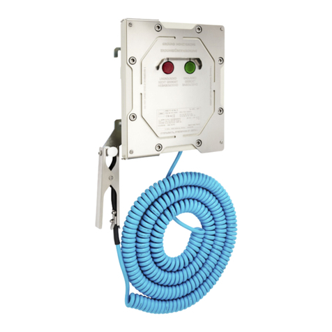
SOMMER RQ-30 ADMS User manual

RQ-30 ADMS
Autonomous Discharge Measurement System
Quick start guide
Manual Version V02
2018-03-27
Sommer GmbH
All rights reserved.

The Copyrights for this manual are exclusively at the company
Sommer GmbH
A-6842 Koblach
This manual may only be multiplied or passed on to third-parties with written permission of the company Sommer. This applies also if
only excerpts of this manual are copied or passed on.
The same conditions apply for passing on in digital form.
Sommer GmbH
Strassenhaeuser 27
6842 Koblach
Austria
http://www.sommer.at
Email:
office@sommer.at
Tel.:
+43 5523 / 55 989 - 0
Fax:
+43 5523 / 55 989 - 19
Validity
This manual applies to the discharge measurement system RQ-30 ADMS and RQ-15 ADMS.

CE compliance
This product is in conformity with the following standards
EMV EN 301 489 - 1 - 3; V 1.6.1
Safety EN 60950 - 1
Health EN 62311
R&TTE EN 300 440 - 2; V 1.2.1
following the provision of directive R&TTE 1999/5/EC.
Safety Information
Please read this entire manual before setting up or operating this equipment. The non-compliance
of this manual could result in damage to the equipment. Also in the case of non-compliance
injuries of individuals cannot be excluded totally.
To make sure that the protection provided of and by this equipment is not impaired, do not use or
install this equipment in any manner other than specified in this manual.

Contents
1. Introduction...............................................................................................................................4
2. Specifications............................................................................................................................4
2.1. General ................................................................................................................................4
2.2. Housing / Dimensions...........................................................................................................5
3. RQ-30 ADMS..............................................................................................................................6
3.1. Block diagram.......................................................................................................................6
3.2. Control Panel........................................................................................................................7
3.2.1. Connector Data Logger..................................................................................................7
3.2.2. Connector Radar............................................................................................................7
3.2.3. Connector Supply Voltage..............................................................................................7
3.2.4. ON / OFF switch ............................................................................................................7
4. First commissioning.................................................................................................................8
4.1. Battery and Sim-Card installation .........................................................................................8
4.1.1. SIM Card........................................................................................................................9
4.2. Software.............................................................................................................................10
4.3. Creating a Station with the communicaton assistent...........................................................11
4.3.1. Modem Testmode........................................................................................................13
4.4. Connecting to a station.......................................................................................................14
4.5. Remote connection via IP Call............................................................................................15
4.6. Load parameters ................................................................................................................17
4.7. Data transmission via HTTP/FTP .......................................................................................18
4.8. Modem...............................................................................................................................18
4.8.1. APN Data.....................................................................................................................18
4.9. Downloading stored data....................................................................................................19
4.10. RQ-30 Radar sensor ........................................................................................................20

4
1. Introduction
The exact and real-time knowledge of the discharge is an important task in the fields of
hydrography, water storage management, irrigation and prevention of natural hazards. It is the
requirement to calculate water structures and for an economical management of water
resources. It is the base for simulations of hydrological processes with mathematical-physical
models.
The RQ-ADMS radar sensor is a continuous measurement device for the contact-free
determination of the discharge of open rivers and channels. It combines two contact-free radar
measurement methods in one system. On one hand the water level is measured by a transit
time measurement of a radar signal. On the other hand the flow velocity at the surface is
simultaneously determined by the principle of Doppler frequency shift. These two
measurements are internally combined and provide the discharge using a predefined mapping
of the measurement site.
Backwater situations caused by inflows, weirs and downstream standing water bodies show
no stable relation between water level and discharge. In many situations hysteresis effects
with different relations for rising and falling water levels occur. Therefore the determination of
such relations is affected by a substantial uncertainty. Only the additional information of flow
velocity, given by the RQ, allows the calculation of the discharge under these difficult
conditions.
Due to the contact-free measurement approach the radar sensor usually can be installed on
bridges or extension arms without expensive structural measures in the river or channel. The
radar sensor is located outside the danger area of flood events and allows a low maintenance
operation over many years.
2. Specifications
2.1. General
General
Total weight
15,5kg (+7,4kg batteries)
Accumulator capacity / voltage
24Ah / 12V
Current consumption (@12V)
sleep
0,8-1,0mA
measure
50-80mA
transmit
50-200mA
Recommended solar panel
50W
Operating temperature
-20…60 °C
Protection rating
IP 66
Lightning protection
Integrated protection against indirect lightnings with a
discharge capacity of 0,6 kV Ppp
Table 1: General specifications

5
2.2. Housing / Dimensions
The RQ-ADMS radar sensor is embedded in a system housing made of powder coated
aluminum.

6
3. RQ-30 ADMS
3.1. Block diagram
The RQ-30 discharge measurement sensor is connected to the MRL-7 data logger which
records all measured values. The data logger contains a 3G modem via which the recorded
data can be sent to user defined servers. Additionally, this configuration offers the possibility
to remotely access the MRL-7 and RQ-30 to change paremeter settings.
Figure 1: RQ-30 ADMS block diagram
RQ-30 MRL-7
Datalogger
antenna
RS-232
RS-485

7
3.2. Control Panel
The RQ-30 ADMS offers the following control panel
Figure 2: Control Panel RQ-30 ADMS
3.2.1. Connector Data Logger
This connector is used to connect the datalogger with an USB-cable (RS-232) to the computer
to perform all the settings.
3.2.2. Connector Radar
This connector is used to communicate directly with the RQ-30 radar sensor. An USB to RS-
485 converter is shipped with your RQ-ADMS unit.
3.2.3. Connector Supply Voltage
This connector is used to supply the RQ-30 ADMS device. With this connection charging of
the internal batteries is performed. It is also possible to connect a solar panel for charging the
batteries.
3.2.4. ON / OFF switch
Switch Position
Function
OFF
The RQ-30 ADMS unit is switched completely OFF
ON
The unit is in standard mode of operation
1
Connector for direct communication with the
data logger (via USB to RS-232 cable)
2
Connector for direct communication with the
RQ (via USB to RS-485 cable)
3
Connector for the main supply voltage
4
ON / OFF switch

8
4. First commissioning
The first startup has to be performed in the following order.
4.1. Battery and Sim-Card installation
Remove all four thumbscrews
Remove upper housing cover
Slide out batterie drawers
Instert batteries

9
Connect the batteries as shown
Push battery drawers back in
4.1.1. SIM Card
If the used SIM card is locked by a PIN code, the PIN code has to be configured in the MRL-7
menu. A wrong PIN code in the MRL-7 menu will lock the SIM card as soon as the device was
started three times! If the SIM card is not locked by a PIN code, this menu item must be set to
“-1”.
It is possible to change or deactivate the PIN number, but not within the MRL-7. This has to be
done with another device (e.g. a mobile phone). The call forwarding option has to be
deactivated in every case by the phone provider to disable the mailbox.
A valid SIM card has to be placed in the marked slot of the integrated modem. It is important
to assure thecorrect plug direction. The SIMcard also has to be placed straight into the modem
and has to be locked in the device after the insertion:
Insert sim card in the marked slot
Further instructions are available in
the MRL-7 manual.

10
4.2. Software
All device settings can be adjusted with Sommer’s software Q-Commander.
The software is shipped on a thumb drive with your RQ-ADMS unit.
To edit the parameters with the PC software Q-Commander, the “Expert” mode must be active
(for more details see Q-Commander manual):
Set “Expert” mode
The PC software Q-Commander highlights the edited parameters. After uploading the changes
to the MRL-7 and the RQ-30/RQ-15, the modified parameters are active (for more details see
Q-Commander manual).

11
4.3. Creating a Station with the communicaton assistent
The connection between the MRL-7 and a computer is established via the RS-232/USB
converter (provided with your RQ-ADMS unit) or via Bluetooth.
Make sure your USB-to-RS232 converter is connected to your PC or respectively that your
Bluetooth adaptor is turned on.
Start the Q-Commander Software.
In the right section of the program under the heading [Commands] chose [Communication
assistant]:
The following window opens:
Choose serial connection if you are using the
RS-232 to USB converter or choose Bluetooth if
used and press next
Make sure the RQ-ADMS is connected and
supplied, then press next
Check the dot that is marked with Logger
Select the checkmark “Scan ports”
proceede with [Next]

12
Wait until all serial ports of your computer are
scanned
Select a name for your new connection or use the
default setting provided by the Software.
proceede with [Next]
The Q-Commander now scans automatically for
devices.
Proceed with pressing [Yes]
Exit the communication assistant by pressing
[Finish]

13
4.3.1. Modem Testmode
When all modem and internet transmission related settings are defined Sommer suggests
using the integrated Modem Testmode to check the data transmission.
Press two times and select the menu “*** settings ***”. Confirm your selection by pressing
and input the separately provided access code.
Use the buttons and to navigate to menu item “10 Modem Testmode” and press
to confirm your selection.
>10 Modem Testmode
A number of automatic tests are performed and related information are displayed:
The modem is initialized.
The SIM card IMSI is displayed for a short amount of time.
To freeze the display press and hold hold the button.
The signal strength is tested and displayed.
The defined connections are established:
oThe MRL-7 synchronizes its time with the defined time server.
oData are sent to all defined servers.
oThe MRL-7 IP call function is activated.
Check the defined target servers for data transmitted during the testmode.

14
4.4. Connecting to a station
Make sure your station (highlighted
green) is selected
Press connect
The green rectangele showing your station and connection shows that you are now connected
to the station.

15
4.5. Remote connection via IP Call
Select the Tab [Connections (F8)] and press [New connection] as shown in the image above.
Choose a Name for your connection and select
the “IP Call” as type.
Then press [Save connection] on the left side
of the Q-Commander window.
Switch back to [Stations (F7)] and select your Station

16
Thick the Checkmark on your IP-Call
connection
Enter the IMSI number in the field
underlined in red.
If the IMSI-Number isn’t known:
The IMSI number can be read from an
inserterted SIM card by using the
“Modem Testmode” feature on the
MRL-7; see the MRL-7 manual for
more details
To finish the setup of your IP-connection press [Save station] on the left side of the Q-
Commander
To connect your station via IP-Call select your preveiosly defined conection and press [Connect]

17
4.6. Load parameters
Press [Connect] to open the cennoction to your RQ-ADMS
Press [Download parameters from all devices]

18
4.7. Data transmission via HTTP/FTP
When data are transferred to a server via HTTP or FTP protocol all data stored on the logger
will be sent to the defined server(s).
The first transmission includes all data recorded so far. Further transmissions will include all
data recorded since the last successful transmission.
In case the data could not be transferred (e.g. because of bad cell reception) the “missing”
data will be sent on with the next succesfull transmission.
4.8. Modem
Data recorded by the integrated MRL-7 can be transmitted to user defined servers (HTTP
and/or FTP).
The modem supply voltage is controlled by the data logger. It is only switched on when a data
transfer has to be performed to save on power consumption. Additionally the modem is
switched on for one hour per day to allow for remote connections to be established with the
system.
To make the modem capable for data transmission a SIM Card has to be inserted. Next, the
APN data and the mobile network defined for the SIM card have to be selected.
4.8.1. APN Data
Establishing a GPRS connection requires setting the correct APN access data (server, user
name and password) which depend on the used network operator.
The APN settings can be set either manually or the settings are chosen from a predefined list
with the software Commander:
Press the [Select APN] button

19
The List in the image above pop’s up and you can find your service provider.
Important:
For detailed information please refer to the MRL-7 user manual.
4.9. Downloading stored data
Make sure that the Q-Commander Software is connected with your station
Press the “Transfer data” button (highlighted red) to initiate the download of the stored data on
the device
Table of contents
Other SOMMER Measuring Instrument manuals
Popular Measuring Instrument manuals by other brands
Velleman
Velleman DCA150B manual
TSI Incorporated
TSI Incorporated 4040 Operation and service manual
iCheckTPMS
iCheckTPMS IC005 instruction manual
ATAGO
ATAGO PAL-HIKARi 2 instruction manual
GOK
GOK SmartBox 1 Assembly and operating instructions
Agilent Technologies
Agilent Technologies 1260 Infinity user manual
Herutu
Herutu 21UD instruction manual
Lascar
Lascar DPM 342 quick start guide
Bürkert
Bürkert 8222 ELEMENT NEUTRINO operating instructions
Endress+Hauser
Endress+Hauser Proline Prosonic Flow 92F Series Safety instructions
Measurement Computing
Measurement Computing USB-1096HFS user guide

Omega
Omega FTB700 user guide
