SOMMER SPA User manual

SPA
Snow Pack Analyzer
Document version: 2012-Jan
Software version: 3.33
User Manual
S
ommer
M
easurement System
T
echnology.
All rights reserved.

User Manual SPA Snow Pack Analyser
Contents
1.
GENERAL INFORMATION...................................................................................................................................... 1
1.1.
P
RINCIPLE OF MEASUREMENT
..............................................................................................................................1
1.2.
M
EASUREMENT PARAMETERS
..............................................................................................................................2
2.
HARDWARE............................................................................................................................................................... 3
2.1.
SPA-
SENSORS
.....................................................................................................................................................3
2.2.
C
ORRECTION LENGTH SENSOR
(
POTENTIOMETER
).............................................................................................3
2.3.
S
NOW DEPTH SENSOR
..........................................................................................................................................3
2.4.
C
ONTROL UNIT
IASP............................................................................................................................................3
2.5.
F
RAMEWORK
.........................................................................................................................................................4
3.
INSTALLATION.........................................................................................................................................................5
3.1.
M
EASUREMENT SITE
.............................................................................................................................................5
3.2.
F
RAMEWORK
.........................................................................................................................................................5
3.3.
S
NOW DEPTH SENSOR
..........................................................................................................................................5
3.4.
S
LOPING
SPA-
SENSOR
........................................................................................................................................6
3.5.
C
ORRECTION LENGTH SENSOR
............................................................................................................................8
3.6.
H
ORIZONTAL
SPA-
SENSORS
................................................................................................................................9
3.7.
H
OUSING
.............................................................................................................................................................10
3.8.
P
OWER SUPPLY
..................................................................................................................................................10
3.9.
S
UMMARY
............................................................................................................................................................10
4.
PARAMETERIZATION...........................................................................................................................................11
4.1.
C
ONNECTION ESTABLISHMENT VIA TERMINAL
....................................................................................................11
4.1.1.
Local communication...............................................................................................................................11
4.1.2.
Connection affirmation............................................................................................................................. 11
4.2.
M
AIN
M
ENU
.........................................................................................................................................................12
5.
NECESSARY PARAMETER ADJUSTMENTS AFTER ASSEMBLY.............................................................13
5.1.
S
NOW DEPTH
......................................................................................................................................................13
5.2.
D
ISPLACEMENT OFFSET
/
L
ENGTH CORRECTION
...............................................................................................13
5.3.
G
EOMETRIC PARAMETERS
..................................................................................................................................14
5.4.
A
CTUAL
S
NOW DEPTH
........................................................................................................................................15
5.5.
M
EASUREMENT INTERVAL
...................................................................................................................................15
6.
DESCRIPTION OF THE PARAMETERS.............................................................................................................17
7.
DATA OUTPUT........................................................................................................................................................27
7.1.
P
ROTOCOL VALUES
.............................................................................................................................................27
7.2.
MIO
P
ROTOCOL
..................................................................................................................................................29
7.3.
S
TANDARD PROTOCOL
........................................................................................................................................31
8.
SUPPORT.................................................................................................................................................................32
9.
BASE SETTINGS AND DEFAULT VALUES......................................................................................................33
10.
TECHNICAL DATA.............................................................................................................................................35

User Manual SPA Snow Pack Analyser
Safety Information
Please read this entire manual before setting up or operating this equipment. The non-compliance of this
manual could result in damage to the equipment. Also in the case of non-compliance injuries of individuals
cannot be excluded totally.
To make sure that the protection provided of and by this equipment is not impaired, do not use or install
this equipment in any manner other than that specified in this manual.

User Manual SPA Snow Pack Analyser
- 1 -
1.General information
Snow has an enormous variability in space and time. Up to now mainly punctual measurements are
available for the relevant parameters. The Snow Pack Analysing System (SPA) constitutes an innovation
in snow measurement. It is a system for automatic and continuous measurement of all relevant snow
parameters like snow depth, snow density, snow water equivalent and contents of liquid water and ice.
There are several possibilities to install the system, depending on demand.
1.1. Principle of measurement
Fig. 1: Principle of measurement of the SPA-sensor
Snow consists of the three components ice, water and air. Referring to different measurement
frequencies, these components show different dielectric constants. Measuring the complex impedance
along a flat ribbon sensor (SPA-sensor) with at least two frequencies allows to estimate the volume
contents of the individual components. These specific volume contents equate the liquid water, ice and air
in the snow pack, which result in the snow density and the snow water equivalent.

User Manual SPA Snow Pack Analyser
- 2 -
1.2. Measurement parameters
Snow density
The SPA calculates the snow density of the snow surrounding the SPA-sensor.
Snow water equivalent SWE
The SWE corresponds to the water column in mm resulting from the melting of the complete snow cover
on a defined area. It is calculated from the snow density of sloping sensors with respect to the snow
depth.
Contents of liquid water and ice in snow pack
The volumetric contents of ice and liquid water in the snow are output in %.
Snow depth
The snow depth is measured by an ultra sonic sensor. It is necessary to determine the SWE.

User Manual SPA Snow Pack Analyser
- 3 -
2.Hardware
Fig. 2: SPA-sensor
Fig. 3: IASP control unit
2.1. SPA-sensors
The SPA-sensor is a 6 cm wide flat ribbon sensor including three copper wires. The length varies between
3 and 10 m. Its ends are terminated by boxes including mounting rings. The connection cable is led out of
one box.
2.2. Correction length sensor (potentiometer)
The deforming of sloping sensors due to the snow pack can be corrected by measuring the additional
length of the sensor rope at the suspension. The sensor measures the rotation of the suspension roll and
converts the values into length. The correction is automatically included in the calculation.
2.3. Snow depth sensor
The snow depth sensor USH-8 is based on transit-time measurements of an ultrasonic pulse between the
sensor and the snow surface. It is mounted with an extension arm on a mast and is directly connected to
the control unit.
The snow depth is an essential parameter to calculate the snow pack parameters of sloping sensors. On
one hand the length of the sensor in snow is determined and on the other hand the total SWE is
calculated using the actual snow depth.
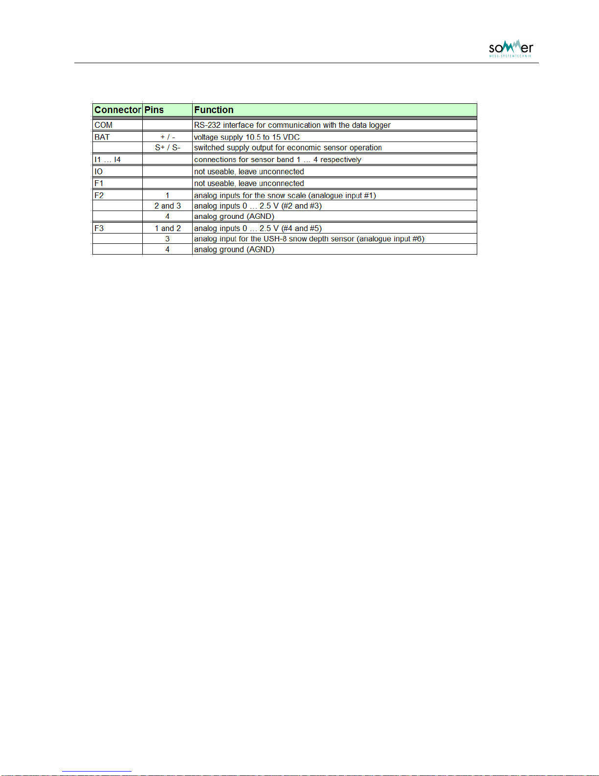
2.4. Control unit IASP
The control unit IASP performs all measurements, switches between sensors and calculates the snow
parameters with respect to snow depth, length correction and geometric parameters. The data is output
via a RS-232 interface.
The analogue input F2-1 (#1) is preadjusted for the length correction. The analogue input F3-3 (#6) is
preadjusted for the USH-8 snow depth sensor.
User Manual SPA Snow Pack Analyser
- 4 -
Tab. 1: Connector assignment for Fig. 3;
the analogue input F3-3 (#6) is reserved for the USH-8 snow depth sensor
2.5. Framework
The framework enables the installation of one sloping and up to three horizontal sensors and secures a
tight and upright positioning of the sensors. It includes the basement framework, a mast for the installation
of the sloping sensor, the snow depth sensor and the housing and suspension equipment for the SPA
sensors consisting of springs, levers and stretching devices.
User Manual SPA Snow Pack Analyser
- 5 -
3.Installation
3.1. Measurement site
A representative measurement site is horizontal and is not located in a basin or on a ridge. It is free of
influences from trees or rocks and is not exposed to intensive winds. An undisturbed accumulation of the
snow pack has to be guaranteed.
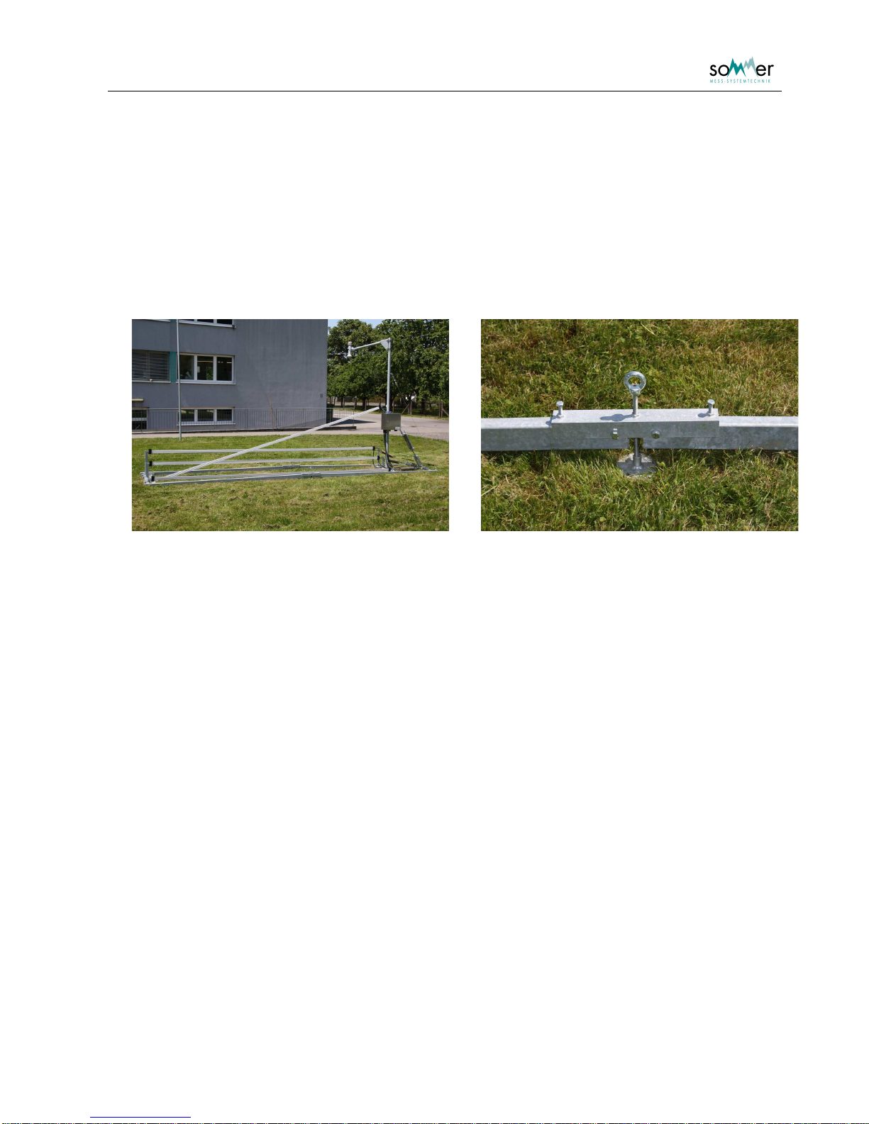
3.2. Framework
Fig. 4: SPA framework Fig. 5: Connection construction with foot
First the basement framework is placed on the ground. It is delivered separated in two parts each with
about two 3 m long beams connected with cross-beams. The side with the two round cross-beams is for
the installation of the mast and the fixation of the suspension, the side with the rectangle cross-beam is
used for fixing the sensors. The inner L-shaped cross-beam can be located at three position, depending
on the installation height of the sloping sensor of 1.5, 2 or 2.5 m.
The two parts of the framework are connected with a connection construction consisting of a u-profile,
screws and a foot. It is important to install the framework with an initial tension to resist the forces of the
spanned sensors. This is achieved by connecting the two parts of the framework in a small angle, support
it with the foot and fix it with the screws. The height of the foot should be at least 10 cm.
After the installation of the basement the mast is installed on the inner cross-beam. The mast holds the
snow depth sensor, the rolls for the sloping SPA-sensor and the housing for the measurement and
communication devices. It is recommended to install the snow depth sensor before erecting the mast. The
mast is supported with two steel wires to be spanned to the near edges of the basement.
3.3. Snow depth sensor
The snow sensor is an ultra sonic sensors using transit time measurement. It is installed on the top of the
mast using the extension arm. The installation height has to be 1 m above the expected maximal snow
depth. The extension arm should be orientated on one side of the framework to guarantee a snow
measurement free of influences. Ensure that the area of the snow depth measurement is free of
constructions, sensors or cables and that it will be undisturbed during the complete winter season. Use
barrier tapes to prevent accidental entering of the area.
User Manual SPA Snow Pack Analyser
- 6 -
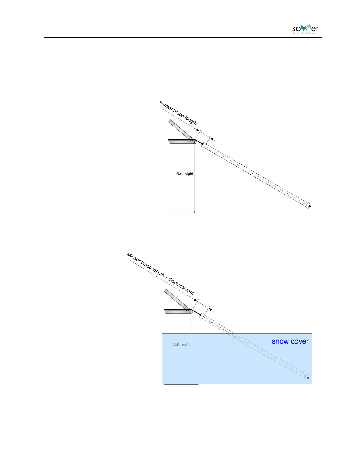
3.4. Sloping SPA-sensor
At the skew SPA the bend of the sensor which is also with strong tension not preventable at snow cover
has to be considered.
Without snow cover the sensor
has, caused by the tension, a
straight course.
Fig. 6: Sketch of the sloping sensor, the
tensioner part differs for simplicity from reality
With snow cover it is
possible that the
sensor has at the air /
snow boun-dary a
slight bend.
The sensor is not
stretchable but
nevertheless the bend
leads to an extension
of the fractional part of
the sensor which is
covered by snow.
This increase can be
determined over the
length change in the
sensor brace length.
Fig. 7: Sketch of the sloping band with a snow cover; the slight
bend in the sensor is best noticeable at the symmetry
lines
User Manual SPA Snow Pack Analyser
- 7 -
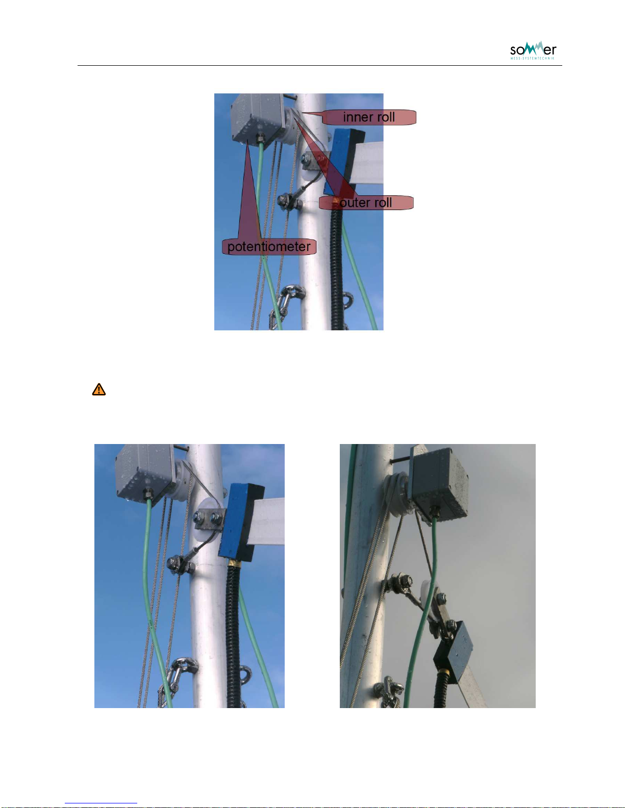
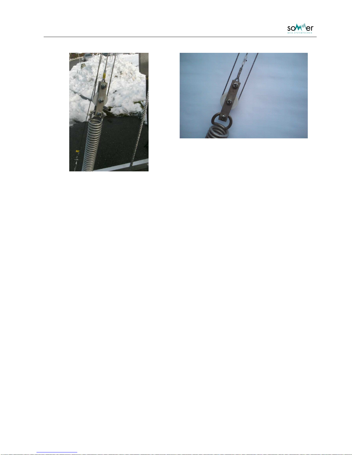
Fig. 8: Upper end of the sloping sensor with the upper part of the tensioner; consider that
the potentiometer is not included at every SPA
Attention: The inner and outer roll rotate at a length displacement with different extent.
The rotation is only measured at the outer roll. So it is very important that the
ropes are not interchanged during the assembling.
Fig. 9: Upper end of the sloping sensor with the upper part of the tensioner from different
views
User Manual SPA Snow Pack Analyser
- 8 -
Fig. 10: Suspension at top of the spring with the pulley sytem (overview and detail)
The installation height of the sloping SPA-sensor should be higher than the maximum expected snow
depth. On the mast are three predrilled positions at heights of about 1.5, 2 and 2.5 m. Depending on the
selected height the L-shaped cross-beam is installed at the predefined positions at the far end of the
framework. The higher the sensor is spanned, the nearer the cross-beam is located, where the bottom
end of the SPA-sensor is fixed.
To span the sensor a spring and pulley system is used, that is spanned by a stretching device. The
stretching device is fixed at the near end of the framework and connected to the spring. The small bar with
the lower roll of the pulley system is connected to the opposite side of the spring. The rope of the pulley
system is fixed at the top screw of the bar connected to the spring. Then it is guided to the inner roll fixed
on the mast, back to the roll on the pulley system, up to the outer roll on the mast and through the roll of
the sensor. Finally it is connected to the screw located bellow the rolls on the mast. Then the sensor is
spanned using the stretching device.
3.5. Correction length sensor
If a correction length sensor (potentiometer) is used for the sloping sensor, it is installed at the deflector
roll located on the mast (Fig. 8). The bolt of the sensor has two rotary stop positions. Make sure that the
bolt is in the correct position to react to extensions of the suspension rope.

User Manual SPA Snow Pack Analyser
- 9 -
3.6. Horizontal SPA-sensors
Fig. 11: Spring connection for horizontal sensor
Fig. 12: Far end of framework
Fig. 13: Same as Fig. 11 but from the other side

User Manual SPA Snow Pack Analyser
- 10 -
The horizontal SPA-sensors are installed at predefined levels on the installation rack. The far end of the
sensors are connected at the far end of the framework. Then they are connected to the levers located on
the crossbeam of the mast. The stretching devices are fixed to the round cross-beam at the other end of
the framework. The springs are positioned directly at the levers and connected to the wires of the
stretching devices. Afterwards the sensors are spanned using the stretching devices until the spring has
elongated by about 100 mm and the sensor is 5000 mm long. The horizontal sensors are supported with
about 5 forks to ensure an upright and stable position.
3.7. Housing
Mount the housing on the mast and connect the cables of the SPA-sensors, the snow depth sensor and
the correction length sensor at the marked inputs.
3.8. Power supply
The supply voltage of the complete system is 10,5 to 15 VDC.
3.9. Summary
•Install framework with an initial tension.
•Locate snow depth sensor 1 m above the maximal expected snow depth.
•Install the sloping SPA-sensor higher than the maximal expected snow depth.
•Span the sensor using the stretching device.
•Install correction length sensor and set rotary bolt to correct position.
•Install and Span horizontal sensors by elongating the spring by about 100 mm.
User Manual SPA Snow Pack Analyser
- 11 -
4.Parameterization
4.1. Connection establishment via terminal
4.1.1. Local communication
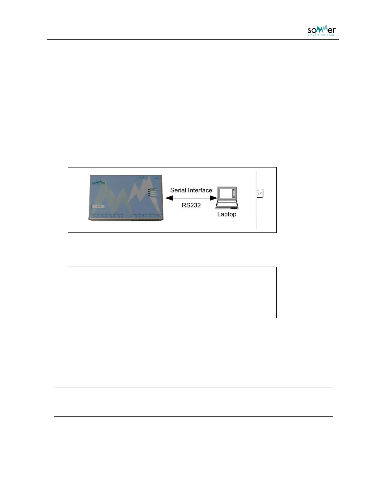
The parameterization of the IASP can be performed by directly connecting the serial interface with a PC or
laptop. Any communication program can be used.
Until Windows XP the terminal program HyperTerminal was included in the Windows operating systems under Start
Programs
Accessories
Communications
HyperTerminal.
The connection cable is a serial data cable with a 1:1 connection (not crossed).
Fig. 14: Connection of the IASP via serial interface
To communicate with the sensor in delivery state the following settings are required:
Baud rate: 9600
Data bits: 8
Parity: none
Stop bits: 1
Flow control: none
Tab. 2: Parameter settings for serial connection
4.1.2. Connection affirmation
If a connection is established and the sensor is switched on, a connection affirmation is sent.
IA-SPA
(c)2006-2012 Sommer GmbH&CoKG
Software version : wdV3.33r01

User Manual SPA Snow Pack Analyser
- 12 -
4.2. Main Menu
The main menu is opened by quickly entering three question marks ??? in the terminal
program.
Fig. 1: Main menu
The menu items are accessed by entering the menu key display left of the menu item. Either sub menus
are opened or the specific parameter is displayed with the corresponding unit. Changes are verified with
Enter
, editing is aborted with
Esc
. Sub menus are closed with
X
. The menu is not case sensitive. If the
main menu is closed, the sensor starts the measurement mode and returns the message Run! .

User Manual SPA Snow Pack Analyser
- 13 -
5.Necessary parameter adjustments after assembly
5.1. Snow depth
The actual snow depth offset is adjusted in Main menu
Analog input
Snow depth adjustment.
5.2. Displacement offset / Length correction
This step applies only for SPA's which include a potentiometer.
Fig. 15: SPA with potentiometer
Fig. 16: SPA without potentiometer
A sloping SPA-sensor is installed with a spring to ensure a tight spanning and to prevent the
sensor from damages due to compression of the snow pack. This non static installation may
cause changes in the sensor position, that can be corrected by measuring the extension
length of the sensor suspension.
In delivery state the length measurement for SPA-sensor 1 is connected to the analog input 1. This
analogue input (channel) is defined for the SPA-sensor in
Main menu
Sensor_01
Input length corr .
Horizontal sensors are operated without length correction by setting the value of the Input length corr. to
“0”.
User Manual SPA Snow Pack Analyser
- 14 -
It is then necessary to adjust the potentiometer which measures the length displacement. Instantly after
the assembling process there is no snow cover on the sensors. Therefor the right offset adjustment is
zero:
Main menu
Analog input
Target value adjustment input_01
0
The actual value is checked with Main menu
8 Sensor_01
6 Input check
5.3. Geometric parameters
The correct calculation of the snow parameters demands the geometric situation of all included sensors.
Especially for the sloping SPA-sensor these settings are used to determine the length of the sensor in the
snow and to correct a smooth inclination of the measurement site.
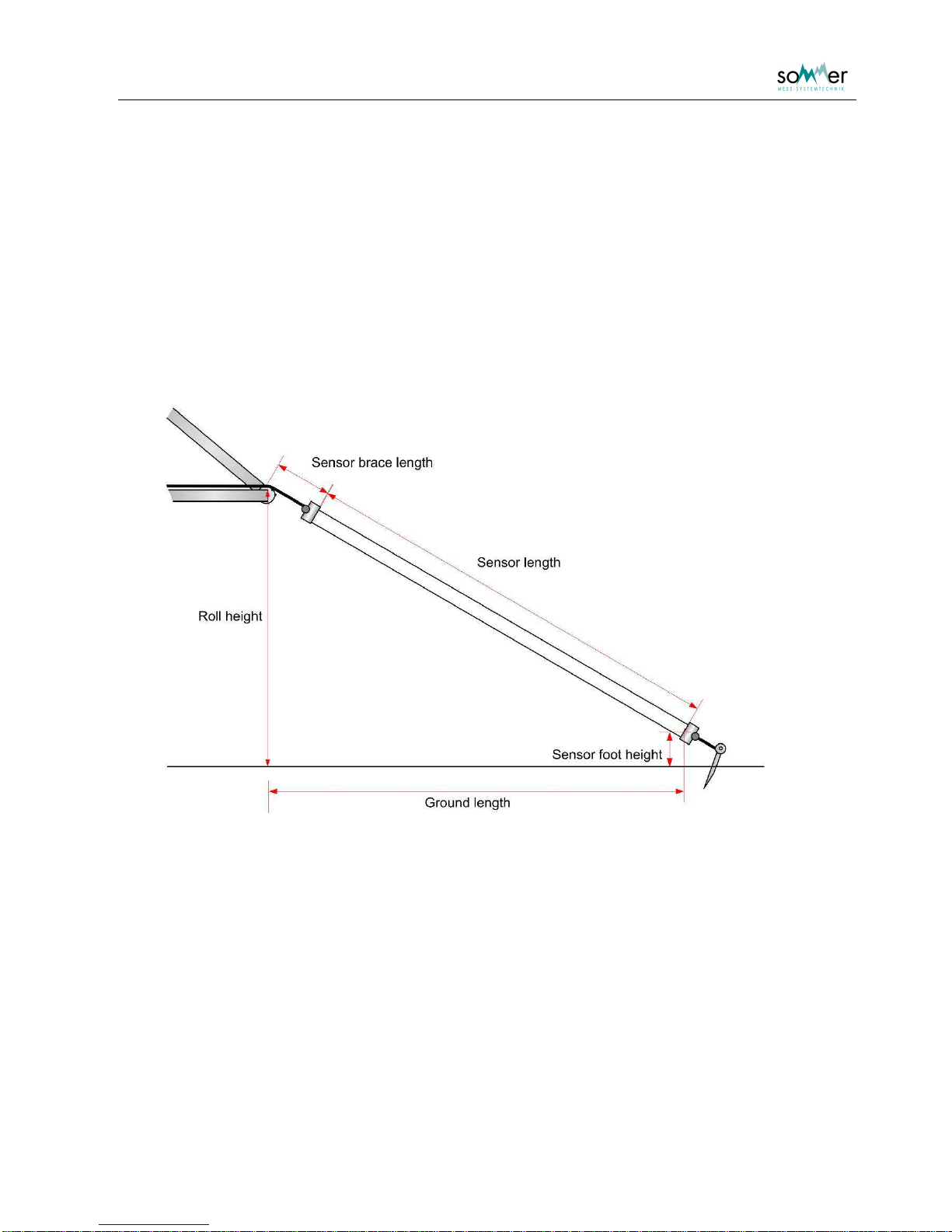
Abb. 2: Geometric parameter of SPA-sensor
Numbering of the sensors
The four in different position mounted sensors are indicated with numbers from 1 to 4. For the standard
SPA the assignment is as following:
odiagonal/slope sensor = sensor 1
ohorizontal, at the lowest level height (100 mm) sensor = sensor 2
ohorizontal, medium level height (300 mm) sensor = sensor 3
ohorizontal, at the highest level (500 mm) sensor = sensor 4

User Manual SPA Snow Pack Analyser
- 15 -
Adjustment
The following geometric parameters are necessary:
•Sensor length: Length of the sensor from one box to the other.
•Roll height: Plumb line height of the top of the roll and the ground
•Foot height: Plumb line height of the middle of the sensor at the lower box and the ground
•Brace length: Distance between the middle of the roll and the sensor at the upper top box.
•Ground length: Distance on the ground between plumb line of roll and plumb line of sensor foot.
For horizontal sensors the roll height and the foot height have to be equal. The brace length is set to “0”
and the ground length is equal to the sensor length.
The geometric parameters are measured with a measuring tape and should be of about 1 cm accuracy.
The geometric parameters are entered into
Main menu
Sensor_01
Main menu
Sensor_02
Main menu
Sensor_03
Main menu
Sensor_04
5.4. Actual Snow depth
The snow depth measurement offset has to be adjusted in the control unit IASP by entering the actual
value in Main menu
6 Analog input
7 Snow depth adjustment
A test measurement of the snow depth is performed with Main menu
6 Analog input
Snow depth
5.5. Measurement interval
The minimum recommended interval is 5 minutes (= 300 s) ( Main menu
2 Meas. interval )
Attention: If the interval is adjusted to a lower value eventually temporary problems in
the meausurement process can occur.
The adjusted default interval is 10 minutes.

User Manual SPA Snow Pack Analyser
- 16 -
Attention: Approximately the first 7 minutes after connecting the SPA to the power
supply the measured values are not reliable if the SPA was disconnected for
more than a moment.
During this startup time invalid measurements are indicated with a value of
9999 pF for the measured low frequency capacity and 0000 pF for the
measured high frequency capacity.
example extened MIO protocol output:
I000000000000000000000409;
I0100-999-008-9990000043F;
I020099990000-9999999046B;
The 7 minutes is the time the internal high capacity electrolytic capacitors need to load. These capacitors deliver the
power for the measurement.

User Manual SPA Snow Pack Analyser
- 17 -
6.Description of the parameters
1 Device identifier
The device identifier is included in the output protocol to identify the data values. The first output string is
assigned with the device identifier. For every following string the device identifier is increased by 1 (see
chapter 7). It is recommended to set the device identifier to
0
.
Value range: 0 to 9999 (default: 0)
Example:
oif Device identifier is adjusted as 0:
I000000000000000000000409;
I0100-999000002510000042A;
I020000100013-862-8860430;
oif Device identifier is adjusted as 3:
I03000000000000000000040C;
I0400-999000002510000042D;
I050000100013-862-8860433;
More details regarding the output strings you can find in chapter 7.
2 Meas. Interval
The measurement interval controls the time for the measurements. For permanent monitoring it is
important, not to set a to short interval. The measurements are performed using a measurement battery. A
to short measurement interval will prevent the battery from charging and the measurement will be invalid.
The recommended interval is 10 minutes (600 s).
Unit: [s]
Value range: 5 to 13980
(default: 600; values greater than 240 are rounded to multiples of 60)
3 Output time
The output of the data is either performed directly after the measurement or the data strings are requested
by a exclamation mark sent via the RS-232 interface.
Table of contents
Other SOMMER Measuring Instrument manuals


