SOMMER SPA-2 User manual

Sommer Messtechnik
All rights reserved.
Manual
Setup version 3.10 (Firmware 2.20)
02 September, 2020
SPA-2
Snow pack analyzer

The Copyrights for this manual are exclusively owned by
Sommer Messtechnik
6842 Koblach
Austria
This manual or parts of it may only be copied or passed on to third parties with written permission
of Sommer Messtechnik. This applies to printed as well as digital issues of this manual.
Sommer Messtechnik
Strassenhäuser 27
6842 Koblach
Austria
www.sommer.at
E office@sommer.at
T +43 5523 55989
F +43 5523 55989-19
Validity
This manual applies to the Snow pack analyzer with the setup version 3.10, including all its sub-
versions.
Created: 19 Sept, 2018 Last update: 02 September, 2020

EU conformity
This product is in conformity with the following standards:
EMC 2014/30/EU EN 301 489-1 V1.9.2
LVD 2014/35/EU EN 62311:2008
EN 62368-1:2014
RoHS II 2011/65/EU
RoHS III 2015/863/EU
Feedback
Should you come across any error in this manual, or if you miss information to handle and operate
the SPA-2 we are very grateful for your feedback to office@sommer.at.

Safety information
Please read this manual carefully before installing or operating this equipment. Non-compliance
with the instructions given in this manual can result in failure or damage of the equipment or may
put people at risk by injuries through electrical or mechanic impact.
lInstallation and electrical connections must be carried out by qualified personnel familiar
with the applicable regulations and standards.
lDo not perform any installations in bad weather conditions, e.g. thunderstorms.
lPrior to installation of equipment inform the owner of the measurement site or the authority
responsible for it. Upon completion, secure the installation from trespassers.
lMaintenance and repair must be performed by trained personnel or an engineer of Sommer
Messtechnik. Only replacement parts supplied by Sommer Messtechnik should be used for
repairs.
lMake sure that NO power is connected to the equipment during installation and wiring.
lOnly use a power supply that complies with the power rating specified for this equipment.
lKeep equipment dry during wiring and maintenance.
lIf applicable, it is recommended to use accessories of Sommer Messtechnik with this equip-
ment.
Disposal
After this device has reached the end of its lifetime, it must not be disposed of with
household waste! Instead, dispose of the device by returning it to a designated col-
lection point for the recycling of waste electrical and electronic equipment.

Content
1 What is the SPA-2? 9
2 Unpacking 10
3 How do I start? 12
3.1 Connect the SPA-2 to a PC 12
3.2 Configure the sensor 13
3.3 Acquire measurements 13
4 Specifications 14
5 Connectors 16
5.1 Terminals 16
6 How does the SPA-2 work? 20
7 Installation 21
7.1 Where should I install the SPA-2? 21
7.2 What do I need? 21
7.3 How do I install the SPA-2? 21
7.3.1 General 21
7.3.2 Supporting frame 23
7.3.3 Mast with tilted SPA-2-sensor and USH-9 26
7.3.4 Tilted SPA-ribbon-sensor 32
7.3.5 Horizontal SPA-2-ribbon-sensor 35
7.3.6 Control cabinet 37
7.3.7 Wiring 38
7.3.8 Power supply 40
7.3.9 Signal cables 40
7.3.10 Lightning protection 41
8 Maintenance 42
9 Support software Commander 43
9.1 What can I do with it? 43
9.2 How do I install it? 43
9.2.1 System requirements 43
9.2.2 Installation procedure 43

10 Configuration 49
10.1 Configuration with Commander support software 49
10.2 Configuration with a terminal program 51
10.3 Configuration errors 53
10.3.1 Device messages 53
10.4 What do I need to configure? 54
10.4.1 General settings 54
10.4.2 Calibration of SPA-2-ribbon-sensors 55
10.4.3 Zero test and adjustment 56
10.4.4 Span test and adjustment 57
10.4.5 Adjustment of snow depth measurement 58
11 Serial communication 59
11.1 What are the options? 59
11.2 Which data do I get? 59
11.2.1 Exception values 60
11.3 RS-485 61
11.3.1 What is it? 61
11.3.2 What can I do with it? 61
11.3.3 How do I wire it? 61
11.3.4 How do I configure it? 62
11.3.5 How is the output structured? 62
11.3.6 Sommer protocol 62
11.3.7 Standard protocol 65
11.3.8 Which commands are available? 68
11.3.9 Sommer CRC-16 70
11.4 SDI-12 70
11.4.1 What is it? 70
11.4.2 What can I do with it? 70
11.4.3 How do I wire it? 70
11.4.4 How do I configure it? 71
11.4.5 How are commands structured? 71
11.4.6 Which commands are available? 71
11.5 Modbus 75
11.5.1 What is it? 75
11.5.2 What can I do with it? 75
11.5.3 How do I wire it? 75
11.5.4 How do I configure it? 76
11.5.5 How do I switch back to Sommer protocol? 80
11.5.6 Which commands are available? 85

12 Parameter definitions 90
A Measurement trigger 90
B Measurement Interval 90
C Measurement table 91
D Snow depth adjust 95
E Snow depth test 95
F Technics 95
F-A Language/Sprache 96
F-B Decimal character 96
F-C Sleep mode 96
F-D Warm-up time 97
F-E Sommer ID 97
F-F SPA, sensor table 97
F-G SDI-12 service 99
F-G-A SDI-12 address 99
F-G-B SDI12 ‘M’-response 99
F-G-C SDI-2 maximal duration 100
F-G-D SDI-2 sensor search 100
F-G-E SDI-2 change sensor address 100
F-G-F SDI-2 ask for a sensor address 100
F-H RS-485-2 Port 100
F-H-A Baud rate 101
F-H-B Parity, stop bits 101
F-H-C Minimum response time 101
F-H-D Transmitter warm-up time 101
F-H-E Flow control 102
F-H-F Sending window 102
F-H-G Receiving window 102
F-H-H Trig, polling 102
F-H-I Trig, timeout 103
F-H-J Trig, sleep while timeout 103
F-H-K Network scan extension 103
F-H-L Polling delay 103
F-H-M Transparency to RS485-2 104
F-I RS-485-1 Protocol 104
F-I-A Device number 104
F-I-B System key 104
F-I-C Output protocol (OP) 105
F-I-D OP, measurement output 105
F-I-E OP, information 105

F-I-F OP, wake-up sequence 106
F-I-G OP, prefix holdback 106
F-I-H MODBUS, set default 106
F-I-I MODBUS, device address 106
F-J RS-485-1 Port 107
F-J-A Baud rate 107
F-J-B Parity, stop bits 107
F-J-C Minimum response time 108
F-J-D Transmitter warm-up time 108
F-J-E Flow control 108
F-J-F Sending window 108
F-J-G Receiving window 109
G Special functions 109
G-A Device status 109
G-B View setup 109
G-C Set factory default 109
G-D Temp. load factory default 109
G-E Relaunch program 109

1 What is the SPA-2?
Determination of snowpack-properties can be very challenging as they vary significantly in space
and time. The SPA-2 snow pack analyzer measures the volumetric contents of ice and water within
a snowpack, and together with the snow depth calculates the snow water equivalent (SWE) and
snow density.
By measuring the complex impedance along multiple, 4.8 m long, ribbon-shaped sensors, the SPA-
2 acquires area-averaged data about the snowpack at different depth. Other than that, the snow
height is precisely measured with the contact-free ultrasonic level sensor USH-9. This sensor-com-
bination provides an automatic measurement system to continuously monitor the snowpack devel-
opment for hydrological, agricultural and other applications.
Figure 1 SPA-2
1 What is the SPA-2?
Manual 9

2 Unpacking
When unpacking your SPA-2 sensor box please make sure that the following items are present:
Name
SPA-2 including assembly equipment
Manual and Commander Software on USB stick
The assembly equipment comprises the following parts:
ID Description Quantity
1 Base-profile right 1
2 Base-profile left 1
3 Base-profile extension right 1
4 Base-profile extension left 1
5 U-profile (stainless steel) 2
6 Base plate for threaded bolt 2
7 Cross-profile with winches 1
8 Cross-profile with clamp for tilted SPA-sensor 1
11 Cross-profile with mast support and anti-twist clamp 1
12 Mast 1
13 Cross-profile with clamps for horizontal SPA-sensors 1
14 Positioning support 5
15 Pulley for tilted SPA-sensor (mounted on mast) 1
18 Cross-arm 1
19 USH-9 ultrasonic level sensor 1
20 Tension spring for SPA-sensors 2
21 Guy cable for mast (labelled 1) 2
22 Guy cable for mast (labelled 2) 2
23 Guy cable for tilted SPA-sensor (labelled 3) including pulley 1
24 SPA-sensor 2
Pair of plastic clips 7
Plastic cylinders 5
Guy ropes for tilted SPA-sensor 2
Control cabinet with SPA-controller 1
2 Unpacking
10 Manual

Bolts and nuts are pre-mounted.
In case of missing or damaged items please contact your Sommer sales partner.
Available accessories
Art Accessory
19294 USB to RS485 embedded converter cable, 1.8 m
20488 Commander software
20700 SPA-ribbon sensor set for horiz. 300-mm mounting; including tension spring and winch
20694 SPA-ribbon sensor set for horiz. 500-mm mounting; including tension spring and winch
2 Unpacking
Manual 11
3 How do I start?
Follow the steps described below to set the basic configurations and to acquire the first meas-
urement results.
NOTE Perform the first start-up in your lab or office before installing the
equipment in the field!
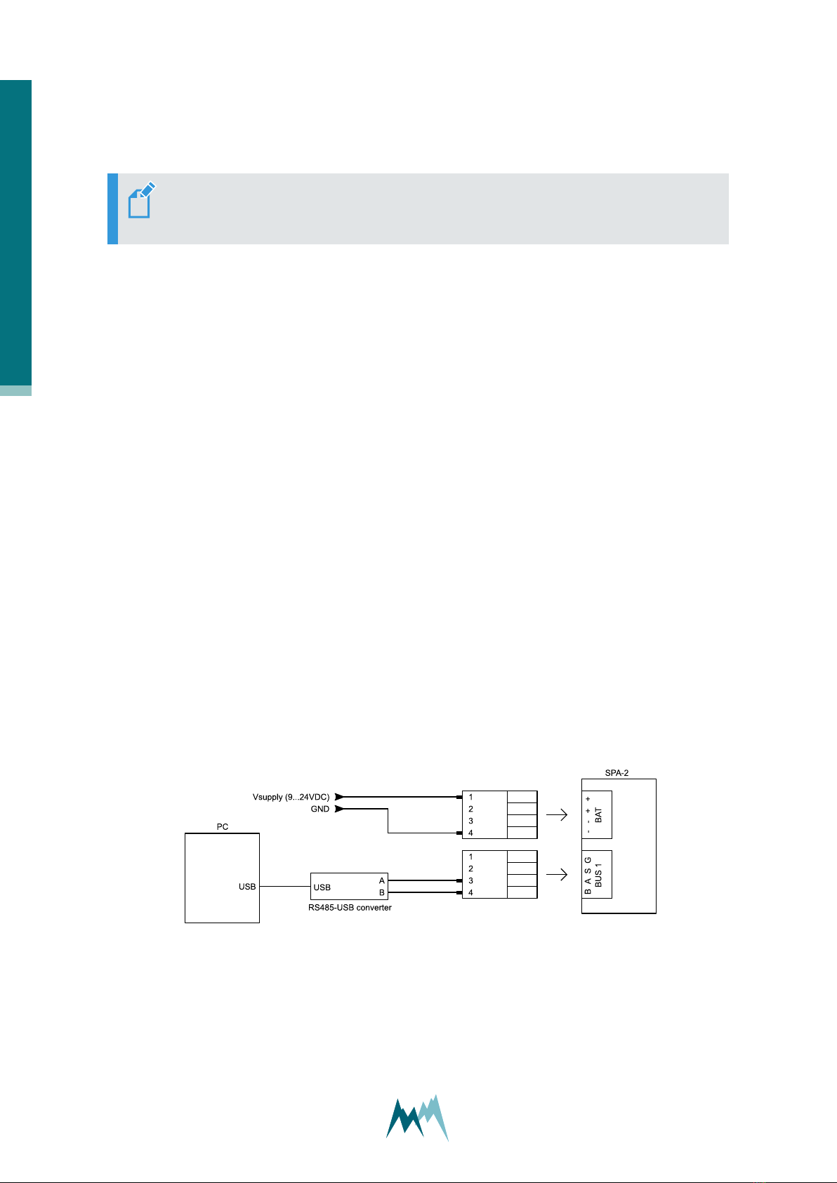
3.1 Connect the SPA-2 to a PC
1. Install the Commander support software (see How do I install it?)
2. Connect the yellow and gray wire of the sensor cable to the USB to RS485 isolated converter
cable and plug it into your PC as illustrated in the figure below.
3. Connect a 9...28 VDC power supply to the SPA-2
4. Start the Commander software.
5. Click on Communication assistant on the right-hand side of the Commander window and fol-
low the instructions. During this procedure the communication assistant will search for con-
nected devices. Upon successful completion, the new connection is added to the connections
list (tab Connections (F8)).
6. In the Communication Section at the right-hand side of the Commander window select Mode
Connection and the previously created connection from the drop-down list.
7. Click Connect to establish a connection with the SPA-2. If the connection was successful a
green icon is displayed at the top-right corner of the Commander window.
8. Select the tab Parameters (F2) and click Download parameters from device on the left side of
the Commander-window. The complete parameter list is transferred from the sensor to your
PC and displayed in the Parameter window.
Figure 2 Wiring of the SPA-2 to a PC
3 How do I start?
12 Manual

3.2 Configure the sensor
1. Select language and decimal character (see General settings)
2. Select the measurement trigger and measurement interval (see General settings)
3. Define the scope and structure of the data output (see General settings)
4. Calibrate the SPA-2 by measuring the capacities of the ribbon sensors in air (see Calibration of
SPA-2-ribbon-sensors)
5. Optional: measure the capacities of the ribbon sensors with a reference plate (see Calibration
of SPA-2-ribbon-sensors))
6. Send any modifications to the SPA-2 by clicking Upload modified parameters to device.
3.3 Acquire measurements
Select the tab Measurement (F3) and click Start polling measurements. Select Polling with meas-
urements and confirm the Warning. Now, the device performs consecutive measurements at the
fastest possible rate. Click Stop polling to cancel data acquisition.
3 How do I start?
Manual 13

4 Specifications
Physical and environmental
Power supply 9...28 VDC; Reverse voltage protection, overvoltage protection
Power consumption at
12 VDC
max. 65 mA active
1mA in sleep mode
Outputs RS-485
SDI-12
Analog output 4…20 mA (14 bit, max. load 200 Ω)
Digital output (low: 0V, high: Vsupply, max. 30 mA at Vsupply-0.5 V)
Operating temperature -35…60 °C (-31…140 °F)
Storage temperature -35…60 °C (-31…140 °F)
Rel. humidity 0...100 %
Protection rating Sensors IP 66
Controller IP 54 (IP 66 if contained in electrical cabinet)
Lightning protection Integrated protection against indirect lightning with a discharge capa-
city of 6 kA Ppp
Housing material Aluminium
Size L x W x H 2.5-m version: 6360 x 1100 x 3700 mm (250.39 x 43.31 x 145.67 in)
5.0-m version: 6360 x 1100 x 5700 mm (250.39 x 43.31 x 224.41 in)
Weight 2.5-m version: 110 kg (242.5 lb)
5.0-m version: 115 kg (253.5 lb)
SPA-sensor
Size L x W 4.8 m x 60 mm (6.3 m for sloping ribbon of 5.0-m version)
Material weatherproof, UV resistant ribbons, reinforced with Kevlar cords
SPA-controller
4 Specifications
14 Manual

Inputs up to 4 SPA-sensors
4x Analog 0 ... 2.5 V, 16 bit
2x Trigger input, low: 0…0.6 V, high: 2…26 V
1x RS-485
1x SDI-12
Outputs 4x Switched power supply (1 for snow depth sensor), max. 0.2 A each
1x RS-485
1x SDI-12
Measurement range and accuracy
Snow depth 0 … 2.5 m
(max. ± 1cm; typically 0.1% FS)
0 … 5 m
(max. ± 1cm; typically 0.1% FS)
Snow water equivalent 0 … 1000 mm (±5% FS) 0 … 3000 mm (±5% FS)
Snow density 0 … 1000 kg/m3(±5% FS)
Volumetric water content 0 … 100 % (±2% FS)
Volumetric ice content 0 … 100 % (±2% FS)
4 Specifications
Manual 15

5 Connectors
5.1 Terminals
All available connection terminals (Figure 3) are listed in the table below.
ATTENTION Serial port BUS 2 is reserved for the USH-9 snow depth input!
Figure 3 Connection terminals of SP-2 controller
Terminal PIN Description
TRIG 2 Trigger input 2 (not available)
G Ground
1 Trigger input 1
G Ground
5 Connectors
16 Manual

Terminal PIN Description
BUS 1 B RS-485 B (to data acquisition device)
A RS-485 A (to data acquisition device)
S SDI-12 (to data acquisition device)
G Ground
BAT - Supply voltage (-)
- Supply voltage (-)
+ Supply Voltage (+), 9.0 to 24.0 VDC
+ Supply Voltage (+), 9.0 to 24.0 VDC
I1 T Optional temperature input
A SPA-ribbon sensor 1
B SPA-ribbon sensor 1
P Shield of SPA-ribbon sensor 1
I2 T Optional temperature input
A SPA-ribbon sensor 2
B SPA-ribbon sensor 2
P Shield of SPA-ribbon sensor 2
I3 T Optional temperature input
A SPA-ribbon sensor 3
B SPA-ribbon sensor 3
P Shield of SPA-ribbon sensor 3
5 Connectors
Manual 17

Terminal PIN Description
I4 T Optional temperature input
A SPA-ribbon sensor 4
B SPA-ribbon sensor 4
P Shield of SPA-ribbon sensor 4
AIN 1,2 G Ground
1 Analog input 1
G Ground
2 Analog input 2
AIN 3,4 G Ground
3 Analog input 3
G Ground
4 Analog input 4
BUS 2 G Ground
S SDI-12 (from sensor)
A RS-485 A (from USH-9)
B RS-485 B (from USH-9)
OUT 1,2 G Ground
1 Switched supply voltage 1: reserved for USH-9
G Ground
2 Switched supply voltage 2
5 Connectors
18 Manual

Terminal PIN Description
OUT 3,4 G Ground
3 Switched supply voltage 3
G Ground
4 Switched supply voltage 4
Table 1:
Connection terminals of SP-2 controller
5 Connectors
Manual 19
6 How does the SPA-2 work?
A snowpack has strong spatial variability and transforms considerably over time. The evaluation of
snow properties and the assessment of snow conditions mostly relies on spot observations. The
snow pack analyzer SPA-2 breaks this limitation and provides information about the snow pack by
measuring the dielectric properties of a large snow volume. It provides all relevant snow properties
like snow depth, snow density, snow water equivalent as well as the contents of liquid water and
ice.
Snow consists of ice, water and air, which have distinctly different dielectric properties. By meas-
uring the complex impedance along a ribbon sensor (SPA-sensor) at two different frequencies, ice,
water and air can be distinguished and their relative volume contents can be determined.
Additionally, snow depth is measured with a USH-9, Sommer’s ultrasonic level sensor. With this
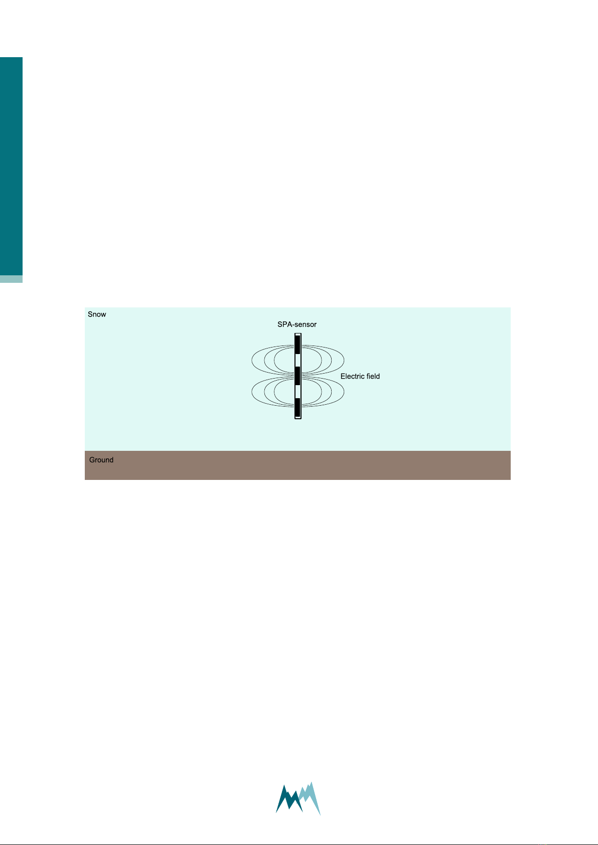
information, snow density and snow water equivalent (SWE) can be calculated. In Figure 4 the cross
section of SPA-sensor and its surrounding electric field is illustrated.
Figure 4 Measurement principle of SPA-sensor
The SPA-sensors are 60 mm wide, reinforced rubber ribbons containing three parallel copper wires.
As soon as an alternating current flows through the wires, an electric field builds up that penetrates
up to 4 cm into the surrounding snowpack.
The 4.8-m long ribbons are stretched onto a supporting frame at different heights either hori-
zontally or in a sloping angle.
The USH-9 ultrasonic level sensor is mounted on the mast of the supporting frame to record the
snow height, which is required to determine the snow coverage of the tilted SPA-sensor and to cal-
culate the snow water equivalent.
6 How does the SPA-2 work?
20 Manual
Table of contents
Other SOMMER Measuring Instrument manuals


