Sonance PS-P43T User manual

PROFESSIONAL SERIES
PENDANT
PS-P43T |PS-P63T |PS-P83T |PS-P83WT
INSTALLATION MANUAL

TABLE OF CONTENTS
PRODUCT DESCRIPTION 2
BOX AND CONTENTS 2
PRODUCT FEATURES 3
PRODUCT PREPARATION
Amplifier Selection 4
Wire Selection
70V/100V System 4
8 ohm System 4
Speaker Placement 4
Grille Painting 5
INSTALLATION 6
TECHNICAL SPECIFICATIONS
PS-P43T 8
PS-P63T 9
PS-P83T 10
PS-P83WT 11
CERTIFICATIONS & SAFETY AGENCY 12
TECHNICAL ASSISTANCE & SERVICE 12
WARRANTY 13
SONANCE |PROFESSIONAL SERIES PENDANT |INSTALLATION MANUAL1

SONANCE |PROFESSIONAL SERIES PENDANT |INSTALLATION MANUAL2
PRODUCT DESCRIPTION
From Sonance, the company that created the architectural
audio category comes a range of professional loudspeakers
that set a new benchmark in sound quality and aesthetics for
commercial environments.
Introducing Sonance Professional Series
Sonance Professional Series includes a range of In-Ceiling, Pendant
and Surface Mount speakers that deliver true full range fidelity,
extremely low distortion, wide dispersion and a smooth power
response. The range also shares consistent voicing, ensuring
seamless sonic integration when used together throughout a space.
The Pendant speakers utilize a minimalistic design similar to
pendant lighting to blend discretely into the environment, and take
advantage of the same one-piece grille design as the In-Ceiling
speakers to deliver consistent sight lines when installed in the same
space. The integrated top cover hides the hanging hardware and
wiring connector. Available in 4”, 6.5” and 8” 2-Way and 8” Woofer
in either black or white.
BOX & CONTENTS
2-WAY SPEAKERS
(2) PS-P43T, or PS-P63T, or PS-P83T
(2) Speaker Grille
(2) Screw-On Top Cover
(2) Hanging Kits Containing:
(4) Stainless Steel Cables with Snap Hooks
(4) Gripple®Hangers
(2) Gripple®Adjustment Tools
(2) Hanging Instructions
WOOFER
(1) PS-P83WT
(1) Speaker Grille
(1) Screw-On Top Cover
(1) Hanging Kit Containing:
(2) Stainless Steel Cables with Snap Hooks
(2) Gripple®Hangers
(1) Gripple®Adjustment Tool
(1) Hanging Instruction
PS-P43T
4” 2-Way
PS-P63T
6.5” 2-Way
PS-P83T
8” 2-Way
PS-P83WT
8” Woofer

SONANCE |PROFESSIONAL SERIES PENDANT |INSTALLATION MANUAL3
Euroblock Connector with Loop Through
Screw-On Top Cover
Paintable Shell (white only)
Hanging Point
High Excursion Woofer
Transformer Tap and Bypass Selector
Once Piece Paintable Grille with Magnetic Retention
Pivoting Chambered Tweeter (excludes PS-P83WT)
Tuning Port
PRODUCT FEATURES

SONANCE |PROFESSIONAL SERIES PENDANT |INSTALLATION MANUAL4
WIRE GAUGE – 70V/100V SYSTEM
The most common wire used on commercial 70 volt systems is
18 gauge, 2 conductor, stranded, and jacketed without a shield.
The wire starts at the amplifier location and is paralleled at each
speaker location.
Wire length using 18 gauge is appropriate up to 700 feet with a
100 watt load. If you double the load (sum of your tap settings),
you will reduce the footage by half, to 350 feet. Conversely, if you
halve the load, you may double the acceptable wire length, i.e.,
a 50 watt load is safe over 1400 feet of 18 gauge. Stepping up to
16 gauge wire extends the allowable run length by approximately
35%. For example, a 100 watt load can go 700 feet on 18 gauge;
the same load may be placed on 1100 feet of 16 gauge.
WIRE GAUGE – 8 OHM SYSTEM
When using Sonance Professional Series loudspeakers in an 8
ohm system the total wire resistance should be less than 10%
of the speaker impedance. The speakers are nominally 8 ohms
impedance, so your total wire resistance should be no more than
0.8 ohms.
In simple terms, the extra resistance from the wire will have a very
negative affect on the sound quality of the speaker. The sound can
be less dynamic, definition of bass frequencies can be reduced,
and in extreme cases, the high frequencies can be attenuated.
Amplifier power is also wasted in the wire, reducing the maximum
output level of the system.
Please refer to the following chart (see figure 1) when deciding on
the appropriate wire gauge for your installation.
Wire Resistance in Ohms vs. Length of Cable Run
20 Gauge
50’ 100’ 150’ 200’ 250’ 300’
.86 1.73 2.59 3.45 4.32 5.18
.65 1.30 1.94 2.59 3.24 3.89
.43 .85 1.28 1.71 2.14 2.56
.27 .54 .81 1.08 1.35 1.62
.17 .34 .51 .68 .85 1.02
Distance in Feet
18 Gauge
16 Gauge
14 Gauge
12 Gauge
AMPLIFIER SELECTION
When choosing an amplifier the maximum number of speakers
and the output level of each speaker must be known. The sum of
the tap settings should never exceed 80% of the amplifier’s rated
output. For example, if there are 5 speakers and the taps are set
at 15 watts, the load would be 75 watts (5 x 15 watts = 75 watts).
To arrive at the needed power for this number of speakers, simply
divide the total load by .8. In this case, 75 / .8 = 93.75 watts.
Therefore, a standard 100 watt amp would safely drive this load.
To calculate the amount of usable power an amp offers, simply
multiply the rated output by .8, i.e., 100 watts x .8= 80 watts.
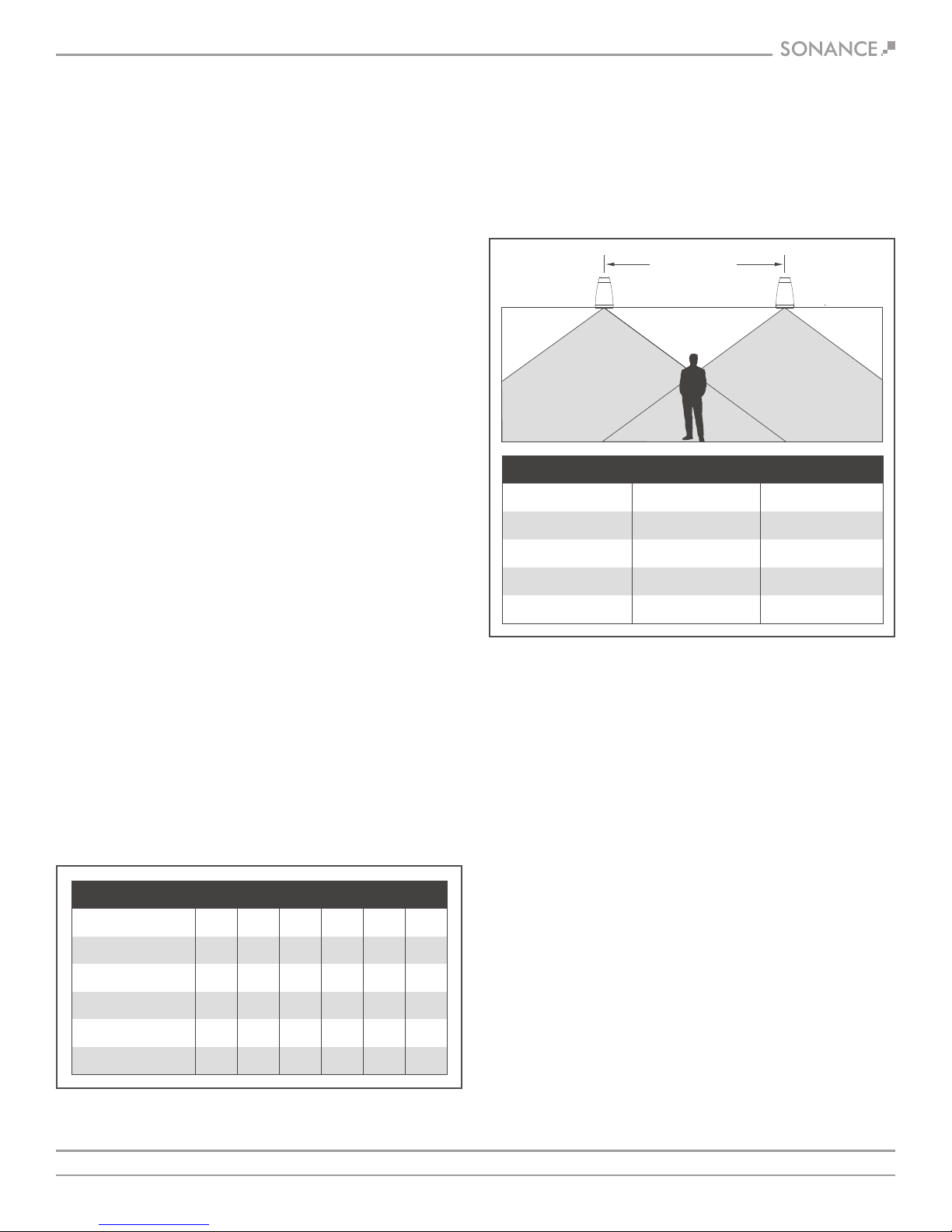
SPEAKER PLACEMENT
Sonance Professional series speakers possess extremely smooth and
predictable off-axis frequency response. The chart below (see figure
2) shows how far apart the speakers can be placed in a distributed
audio system. The calculations are based on +/- 45 degrees of cov-
erage from the speaker, and listener ear heights of 62” for standing
and 40” for seated.
SPEAKER
SPACING
COVERAGE
AREA
COVERAGE
AREA
Speaker Spacing in Feet for a Distributed Audio System
8’ Hanging Height
5.7’ (1.7m) Apart
9.7’ (3.0m) Apart
13.7’ (4.2m) Apart
17.7’ (5.4m) Apart
9.5’ (2.9m) Apart
13.5’ (4.1m) Apart
17.5’ (5.3m) Apart
21.5’ (6.6m) Apart
Standing Listener Seated Listener
10’ Hanging Height
12’ Hanging Height
14’ Hanging Height
FIGURE 1: WIRE RESISTANCE
FIGURE 2: SPEAKER SPACING

SONANCE |PROFESSIONAL SERIES PENDANT |INSTALLATION MANUAL5
PAINTING THE SPEAKER SHELL
Sonance Professional Series Pendant speakers feature a tough
polypropylene enclosure that can be painted. Sonance recommends
using a weather-resistant outdoor paint and a spray gun.
1. If they have already been installed, remove the grilles from
the speakers.
2. To protect the speaker driver units during painting, place the
grilles on a piece of cardboard and trace around their outlines.
Then cut the cardboard just inside of the trace line and fit these
“paint plugs” into the speakers’ baffles. (Be careful not to
damage the driver components while fitting the paint plugs.)
3. Paint the speakers the desired color according to the paint
manufacturer’s instructions. Remove the paint plugs after the
paint has thoroughly dried.
PAINTING THE GRILLES
1. Prime the grille with a metal primer/bonder in a spray can.
Carefully follow the manufacturer’s directions on the can.
2. We recommend using water-based latex paint on the grilles.
Thin the paint with a proper thinning agent to a ratio of 1:1
paint-to-thinner, and strain it through a standard mesh strainer
to remove any lumps.
3. Use a small touch-up gun or cap-spray gun with a #3 tip
for painting.
a. Set the nozzle with a medium to wide fan
b. Set the pressure regulator to 60psi
c. Lightly spray the front of the grille in 3 quick strokes from
approximately 10 inches away.
d. Let the paint set for a minute, then turn the grille 90° and lightly
spray the grille again in 3 quick strokes. Repeat this step until all
four sides of the grille have been evenly painted evenly.
4. While the paint is still wet, inspect the grille and make sure that
excess paint has not collected underneath the grille frame, and
that none of the grille perforations are filled with paint. If any
are, use compressed air to blow the paint out of the perforations.
IMPORTANT: IF YOU FIND ANY GRILLE PERFORATIONS THAT
ARE PLUGGED WITH PAINT AFTER THE PAINT HAS DRIED, USE
A STRAIGHT PIN OR SEWING NEEDLE TO CAREFULLY REMOVE
THE PAINT.
5. Once the paint has thoroughly dried, replace the scrim cloth on
the back of the grille and mount the grille on the speaker.
Gripple Fasteners Carrying Capacity
PS-P43T
KGS
3.01
5.48
8.50
POUNDS
6.64
12.08
18.74
MODEL
PS-P63T
PS-P83T / PS-P83WT
FIGURE 3: GRIPPLE FASTENERS CARRYING CAPACITY
CARRYING CAPACITY
OF GRIPPLE FASTENERS
Sonance Professional Series Pendant speakers are supplied with
Gripple hangers and suspension hardware that exceeds the
required weight requirements. (See figure 3, as well as separate
hanging hardware instruction sheet).

SONANCE |PROFESSIONAL SERIES PENDANT |INSTALLATION MANUAL6
INSTALLING THE SPEAKERS USING
GRIPPLE SUSPENSION SYSTEMS
1. Thread Gripple onto cable
(see inset detail). Pass over
ceiling anchor point
(as shown) or through
other secure anchor point
of the building structure.
Installer is responsible for
ensuring that anchor point
is secure to building structure.
(See figure 4).
2. Thread cable through top
cover of speaker.
(See figure 5).
6. After height adjustment is
final, trim any unneeded
extra cable tail wires with
trimmer suitable for 2mm
(0.077 in) diameter
stranded aircraft-type
cable. Screw back on top
cover of speaker after
speaker wire is connected.
(See figure 9).
3. Pass tail end of cable
through the other
channel of the Gripple.
(See figure 6).
4. With speaker supported,
snap main support hook
hanger onto the center
hole in the top bracket
of the speaker. Adjust to
proper height by pulling
cable through either end
of Gripple. (See figure 7).
7. Make sure the weight of
the load is supported.
(See figure 10).
8. Insert key into small hole at
bottom of Gripple. Push in
1/4” to release the cable.
(See figure 11).
9. Adjust height. (See figure 12).
10. Remove key and re-secure
the load. (See figure 13).
FIGURE 4: THREAD GRIPPLE
FIGURE 8: SECONDARY SUPPORT
FIGURE 9: SCREW ON COVER
FIGURE 10: LOAD SUPPORTED
FIGURE 11: RELEASE CABLE
FIGURE 12: ADJUST HEIGHT
FIGURE 13: REMOVE KEY
FIGURE 5: THREAD CABLE
FIGURE 6: THREAD CABLE AGAIN
FIGURE 7: MAIN SUPPORT
5. Snap secondary support
safety cable hook hanger
onto one of the side holes
in the top bracket of the
speaker, and attach the top
to a different ceiling support
point of the building
structure, per Steps 1 & 2.
(See figure 8).
HOW TO USE RELEASE
KEY TO ADJUST HEIGHT
OF SPEAKER
CAUTION: INSTALLATION MUST BE DONE BY QUALIFIED PERSONS
USING SAFE RIGGING STANDARDS. USE EQUIPMENT ONLY IN
ACCORDANCE WITH MANUFACTURER’S INSTRUCTIONS. DO NOT
ALTER OR MODIFY. DO NOT USE EQUIPMENT IF THE EQUIPMENT
IS NOT FUNCTIONING CORRECTLY OR IF THE EQUIPMENT
IS DEFECTIVE.

SONANCE |PROFESSIONAL SERIES PENDANT |INSTALLATION MANUAL7
11. Connect the wires from your amplifier
to the Euroblock connector.
(See figure 14).
12. Feed speaker wire through the hole
in the top of the Screw-On Top Cover.
(See figure 15).
13. Strip approximately .1875” (5mm) of the insulation off
each wire. Insert the wire into the correct square opening on
the connector. Use a small flat head screwdriver to tighten
the corresponding screw to secure the wire. (See figure 16).
Pin 1 + Positive In
Pin 2 - Negative In
Pin 3 + Positive Out
Pin 4 - Negative Out
+_
IN OUT
+_
14. When using multiple speakers you can connect the speakers
either in parallel or in the loop through method as shown
below (see figure 17 & 18).
16. Determine the proper wattage setting
for each speaker in the installation
and set each speaker’s transformer
tap selector on the front of the speaker
accordingly (see figure 20).
17. Fit the grilles onto the speaker.
(See figure 21).
15. Screw the top cover onto the speaker
(see figure 19).
From Power Amplifier
+_
IN OUT
+_
+_
IN OUT
+_
+_
IN OUT
+_
+_
IN OUT
+_
+_
IN OUT
+_
+_
IN OUT
+_
Parallel Connection To Next SpeakerFrom Power Amplifier
Loop Thru Connection To Next SpeakerFrom Power Amplifier
Parallel Connection
To Next Speaker
+_
IN OUT
+_
+_
IN OUT
+_
+_
IN OUT
+_
+_
IN OUT
+_
+_
IN OUT
+_
+_
IN OUT
+_
Parallel Connection To Next SpeakerFrom Power Amplifier
Loop Thru Connection To Next SpeakerFrom Power Amplifier
From Power Amplifier
Loop Through Connection
To Next Speaker
FIGURE 16:
SECURE THE WIRE
FIGURE 14:
INPUT CONNECTOR
FIGURE 15:
FEED SPEAKER WIRE
FIGURE 18: LOOP THROUGH CONNECTION
FIGURE 17: PARALLEL CONNECTION
FIGURE 20:
TRANSFORMER
TAP SELECTION
FIGURE 19:
SCREW ON COVER
FIGURE 21:
GRILLE INSTALLATION
INSTALLING THE SPEAKERS USING
GRIPPLE SUSPENSION SYSTEMS

SONANCE |PROFESSIONAL SERIES PENDANT |INSTALLATION MANUAL8
PS-P43T TECHNICAL SPECIFICATIONS
LOUDSPEAKER
Frequency Range (-10dB):
Frequency Range (-3dB):
Power Capacity:
Nominal Sensitivity:
Nominal Coverage Angle:
Directivity Factor (Q):
Directivity (DI):
Rated Maximum SPL:
Rated Impedance:
Transformer Taps:
Crossover Point:
Overall Dimension:
Net Weight:
Shipping Weight:
Unit of Measure:
Color:
Grille:
TRANSDUCERS
LF Driver:
HF Driver:
ENCLOSURE
Input Connectors:
Safety Agency:
Suspension Points:
57Hz – 25kHz
75Hz – 20kHz
60 Watts Continuous Program Power
30 Watts Continuous Pink Noise
87dB
120 degrees conical coverage
7.6
8.1dB
105dB @ 1 meter (3.3 feet) average, 110dB peak
8 ohms nominal, 6 ohms minimum
70V: 30W, 15W, 7.5W and 3.8W
100V: 30W, 15W and 7.5W
3000Hz
6.3” Diameter x 11” Depth (160mm x 280mm)
3 lbs (1.36kg) each
14 lbs (6.35kg) pair
Pair
Black or White
Bezel-less magnetically retained grille
4” (100mm) Polypropylene Cone, Butyl Rubber Surround
1” (25mm) Cloth Dome, Pivoting, Ferrofluid cooled
Four pin, Euroblock with loop output connections
UL 1480, UL 2239, NFPA 70
5 Points, top mounted
Included Accessories
•Euroblock Connector x 2
•16.4’ (5m) Stainless Steel
Cable with Snap Hook x 4
•Gripple®Hanger x 4
•Gripple®Adjustment Tool x 2
•Weather Boot x 2
•Grille x 2
Optional Accessories
•Replacement Round Grille White (pair) | 40152
•Replacement Round Grille Black (pair) | 40155
•Replacement Hanging Hardware Kit | 40176

SONANCE |PROFESSIONAL SERIES PENDANT |INSTALLATION MANUAL
PS-P63T TECHNICAL SPECIFICATIONS
LOUDSPEAKER
Frequency Range (-10dB):
Frequency Range (-3dB):
Power Capacity:
Nominal Sensitivity:
Nominal Coverage Angle:
Directivity Factor (Q):
Directivity (DI):
Rated Maximum SPL:
Rated Impedance:
Transformer Taps:
Crossover Point:
Overall Dimension:
Net Weight:
Shipping Weight:
Unit of Measure:
Color:
Grille:
TRANSDUCERS
LF Driver:
HF Driver:
ENCLOSURE
Input Connectors:
Safety Agency:
Suspension Points:
49Hz – 25kHz
65Hz – 20kHz
120 Watts Continuous Program Power
60 Watts Continuous Pink Noise
88dB
120 degrees conical coverage
6.5
7.9dB
108dB @ 1 meter (3.3 feet) average, 116dB peak
8 ohms nominal, 6 ohms minimum
70V: 60W, 30W, 15W and 7.5W
100V: 60W, 30W and 15W
2750Hz
9.13” Diameter x 15.6” Depth (232mm x 396mm)
5 lbs (2.27kg) each
19 lbs (8.61kg) pair
Pair
Black or White
Bezel-less magnetically retained grille
6.5” (165mm) Polypropylene Cone, Butyl Rubber Surround
1” (25mm) Cloth dome, Pivoting, Ferrofluid cooled
Four pin, Euroblock with loop output connections
UL 1480, UL 2239, NFPA 70
5 Points, top mounted
Included Accessories
•Euroblock Connector x 2
•16.4’ (5m) Stainless Steel
Cable with Snap Hook x 4
•Gripple®Hanger x 4
•Gripple®Adjustment Tool x 2
•Weather Boot x 2
•Grille x 2
Optional Accessories
•Replacement Round Grille White (pair) | 40153
•Replacement Round Grille Black (pair) | 40156
•Replacement Hanging Hardware Kit | 40176
9

SONANCE |PROFESSIONAL SERIES PENDANT |INSTALLATION MANUAL10
PS-P83T TECHNICAL SPECIFICATIONS
LOUDSPEAKER
Frequency Range (-10dB):
Frequency Range (-3dB):
Power Capacity:
Nominal Sensitivity:
Nominal Coverage Angle:
Directivity Factor (Q):
Directivity (DI):
Rated Maximum SPL:
Rated Impedance:
Transformer Taps:
Crossover Point:
Overall Dimension:
Net Weight:
Shipping Weight:
Unit of Measure:
Color:
Grille:
TRANSDUCERS
LF Driver:
HF Driver:
ENCLOSURE
Input Connectors:
Safety Agency:
Suspension Points:
41Hz – 25kHz
55Hz – 20kHz
160 Watts Continuous Program Power
80 Watts Continuous Pink Noise
90dB
120 degrees conical coverage
7.6
8.1dB
110dB @ 1 meter (3.3 feet) average, 116dB peak
8 ohms nominal, 6 ohms minimum
70V: 60W, 30W, 15W and 7.5W
100V: 60W, 30W and 15W
2750Hz
11.06” Diameter x 19.7” Depth (281mm x 500mm)
10 lbs (4.53kg) each
25 lbs (11.34kg) pair
Pair
Black or White
Bezel-less magnetically retained grille
8” (203mm) Polypropylene Cone, Butyl Rubber Surround
1” (25mm) Cloth Dome, Pivoting, Ferrofluid cooled
Four pin, Euroblock with loop output connections
UL 1480, UL 2239, NFPA 70
5 Points, top mounted
Included Accessories
•Euroblock Connector x 2
•16.4’ (5m) Stainless Steel
Cable with Snap Hook x 4
•Gripple®Hanger x 4
•Gripple®Adjustment Tool x 2
•Weather Boot x 2
•Grille x 2
Optional Accessories
•Replacement Round Grille White (pair) | 40154
•Replacement Round Grille Black (pair) | 40157
•Replacement Hanging Hardware Kit | 40176

SONANCE |PROFESSIONAL SERIES PENDANT |INSTALLATION MANUAL11
PS-P83WT TECHNICAL SPECIFICATIONS
LOUDSPEAKER
Frequency Range (-10dB):
Frequency Range (-3dB):
Power Capacity:
Nominal Sensitivity:
Nominal Coverage Angle:
Directivity Factor (Q):
Directivity (DI):
Rated Maximum SPL:
Rated Impedance:
Transformer Taps:
Crossover Point:
Overall Dimension:
Net Weight:
Shipping Weight:
Unit of Measure:
Color:
Grille:
TRANSDUCERS
LF Driver:
HF Driver:
ENCLOSURE
Input Connectors:
Safety Agency:
Suspension Points:
32Hz – 300Hz
50Hz – 150Hz
200 Watts Continuous Program Power
125 Watts Continuous Pink Noise
89dB
180 degrees conical coverage
N/A
N/A
110dB @ 1 meter (3.3 feet) average, 116dB peak
8 ohms nominal, 6 ohms minimum
70V: 120W, 60W, 30W and 15W
100V: 120W, 60W and 30W
150Hz
11.06” Diameter x 19.7” Depth (281mm x 500mm)
12 lbs (5.44kg) each
18 lbs (8.61kg) each
Pair
Black or White
Bezel-less magnetically retained grille
8” (203mm) Polypropylene Cone, Butyl Rubber Surround
N/A
Four pin, Euroblock with loop output connections
UL 1480, UL 2239, NFPA 70
5 Points, top mounted
Included Accessories
•Euroblock Connector x 1
•16.4’ (5m) Stainless Steel
Cable with Snap Hook x 2
•Gripple®Hanger x 2
•Gripple®Adjustment Tool x 1
•Weather Boot x 1
•Grille x 1
Optional Accessories
•Replacement Round Grille White (pair) | 40154
•Replacement Round Grille Black (pair) | 40157
•Replacement Hanging Hardware Kit | 40176

CERTIFICATIONS
SONANCE |PROFESSIONAL SERIES PENDANT |INSTALLATION MANUAL12
SAFETY AGENCY COMPLIANCE
Sonance Professional Series Pendant loudspeakers models PS-P43T,
PS-P63T, PS-P83T & PS-P83WT meet the following standards:
UL 1480: Listed Standard For Safety For Speakers for Fire Alarm,
Emergency, and Commercial and Professional Use.
UL 2239: Standard For Safety Hardware for the Support of
Conduit, Tubing, and Cable
NFPA 70: 2002 National Electrical Code
TECHNICAL ASSISTANCE AND SERVICE
The Technical Assistance Department at Sonance is available at
(949) 492-7777 to answer any questions concerning the operation
and installation of your speakers between the hours of 7:00 AM and
5:00 PM Pacific time, Monday through Friday, except holidays.
In the event your unit should need repair or service, you may return
the unit to your authorized dealer or use the following guidelines:
PLEASE KEEP ORIGINAL PACKAGING WHEN POSSIBLE.
1. Be prepared to state the model number and / or serial number,
date of purchase, and dealer’s name and address when calling.
2. Contact Sonance directly at (949) 492-7777 or at www.sonance.com
YOU MUST HAVE PRIOR AUTHORIZATION TO RETURN YOUR UNIT.
3. If you are returning the product directly to Sonance, call us to
obtain a return authorization number before shipping.
4. Ship the product via United Parcel Service, Federal Express,
or other package delivery service. Please do not use the
U.S. Postal Service.
5. Write the return authorization number on the outside of the box.
6. Ship to:
Attn: Quality Assurance Department
Sonance
212 Avenida Fabricante
San Clemente, CA 92672-7531

SONANCE |PROFESSIONAL SERIES PENDANT |INSTALLATION MANUAL13
©2017 Sonance. All rights reserved. Sonance is a registered trademarks of Dana Innovations.
Due to continuous product improvement, all features and specifications are subject to change without notice.
For the latest Sonance product specification information visit our website: www.sonance.com
SONANCE • 212 Avenida Fabricante • San Clemente, CA 92672-7531 USA
(949) 492-7777 • FAX: (949) 361-5151
www.sonance.com/professionalseries
Limited Warranty
Sonance warrants this product to the original purchaser to be free from defects in material and workmanship, under normal use and
conditions, for a period of five (5) years from the date of original purchase as shown on the invoice.
The foregoing exclusive warranty gives you specific legal rights, and you may have other rights, which vary from state to state. This warranty
applies exclusively to the original purchaser.
The exclusive warranty does not apply and is ineffective if:
1. The invoice fails to establish that the product was purchased from an authorized Sonance dealer or distributor;
2. The product was subjected to misuse, neglect, accident, or improper installation.
[Damage to the product was caused by accident, abuse, or misuse];
3. The product was modified, altered, or repaired by unauthorized personnel; or
4. The unit was not used as described in the installation and operating instructions.
Exclusive Remedy
Sonance agrees, at its option during the five (5) year warranty period, to repair any defect in material or workmanship or to furnish an equal
product in exchange without charge to the purchaser, subject to verification of the defect and proof of the date of purchase.
Exclusions
TO THE EXTENT PERMITTED BY LAW, THE WARRANTY SET FORTH ABOVE IS IN LIEU OF, AND EXCLUSIVE OF, ALL OTHER WARRANTIES, EXPRESS
OR IMPLIED, AND IS THE SOLE AND EXCLUSIVE WARRANTY PROVIDED BY SONANCE. ALL OTHER EXPRESS AND IMPLIED WARRANTIES,
INCLUDING THE IMPLIED WARRANTIES OF MERCHANTABILITY, IMPLIED WARRANTY OF FITNESS FOR USE, AND IMPLIED WARRANTY OF
FITNESS FOR A PARTICULAR PURPOSE ARE SPECIFICALLY EXCLUDED.
No one is authorized to make or modify any warranties on behalf of Sonance. The warranty stated above is the sole and exclusive remedy
and Sonance’s performance shall constitute full and final satisfaction of all obligations, liabilities and claims with respect to the Product.
IN ANY EVENT, SONANCE SHALL NOT BE LIABLE FOR CONSEQUENTIAL, INCIDENTAL, ECONOMIC, PROPERTY, BODILY INJURY, OR
PERSONAL INJURY DAMAGES ARISING FROM THE PRODUCT, ANY BREACH OF THIS WARRANTY OR OTHERWISE.
This warranty statement gives you specific legal rights, and you may have other rights which vary from state to state. Some states do not allow
the exclusion of implied warranties or limitations of remedies, so the above exclusions and limitations may not apply. If your state does not
allow disclaimer of implied warranties, the duration of such implied warranties is limited to period of Sonance’s express warranty.
Warranty Exclusions and Damage Limitations
Additional Limitations and Exclusions from Warranty Coverage: The warranty described above is non-transferable, applies only to the initial
installation of the Product, does not include installation of any repaired or replaced Product, does not include damage to allied or associated
equipment which may result for any reason from use with this Product, and does not include labor or parts caused by accident, disaster,
negligence, improper installation, misuse (e.g. overdriving the amplifier or speaker, excessive heat or cold or humidity, outdoor installation),
or from service or repair which has not been authorized by Sonance.
Obtaining Authorized Service: To qualify for the warranty, you must contact your authorized Sonance Dealer/Installer or call Sonance
Customer Service at (949) 492-7777 within the warranty period, must obtain a return merchandise number (RMA), and must deliver the
Product to Sonance shipping prepaid during the warranty period, together with the original sales receipt, or invoice or other satisfactory
proof of purchase.
WARRANTY, REMEDY, EXCLUSIONS AND LIMITATIONS (U.S. ONLY)
01.11.17
This manual suits for next models
3
Table of contents