SONASONIC S4 User manual

Copyright © 2014 Sonasonic Technologies Private Ltd. All rights reserved.
SONASONIC S4 Vehicle Tracker
User Guide

Copyright © 2014 Sonasonic Technologies Private Ltd. All rights reserved.
Contents
1. Copyright and Disclaimer..............................................................................3
2. Applications ................................................................................................3
3. Product Function and Specifications ...............................................................3
3.1 Product Function............................................................................................3
3.2 Specifications................................................................................................4
4. S4 and Accessories ......................................................................................5
5. View ..........................................................................................................5
6. First Use.....................................................................................................5
6.1 Install SIM Card.............................................................................................5
6.2 Charging ......................................................................................................6
6.3 LED Indications .............................................................................................6
6.4 Track by Calling.............................................................................................7
7. Installation ............................................................................................... 17
7.1 Install I/O Cable..........................................................................................17
7.1.1 Power/GND (PIN1, PIN2) ..................................................................... 17
7.1.2 Digital Input (PIN 3, Negative Triggering)/SOS ....................................... 18
7.1.3 Digital Input (PIN10, Positive Triggering) ............................................... 18
7.1.4 Output (PIN6)..................................................................................... 18
7.2 Mount the S4 unit ........................................................................................ 19

Copyright © 2014 Sonasonic Technologies Private Ltd. All rights reserved.
1. Copyright and Disclaimer
Copyright © 2014 SONASONIC. All rights reserved
SONASONIC and are trademarks that belong to Sonasonic Technologies Pvt. Ltd.
The user manual may be changed without prior
notification.
This user manual, or any part thereof, may not be reproduced for any purpose whatsoever without the written
authorization of SONASONIC,or transmitted in any form, either electronically or mechanically, including
photocopying and recording.
In no event shall SONASONIC be liable for direct, indirect, special, incidental, or consequential damages (including
but not limited to economic loss, personal injury, and loss of asset and property) arising out of the use or inability
or illegality to use the product or documentation.
2. Applications
3. Product Function and Specifications
3.1 Product Function
Vehicle Real Time Tracking
Car Security/Anti-Hijack
Tracking for Motorcycles, Yachts and Boats
Fleet Management
U-blox 6 GPS and Quad Band GSM 850/900/1800/1900Mhz
AGPS ( with GSM Base Station ID)
Waterproof (IP66)
Inbuilt GPS and GSM Antenna
Track bySMS/GPRS (TCP/UDP)
Track onDemand
Track byTime Interval
Track by Distance Interval
Track on Mobile Phone
Internal 8MbMemory for Logging
Inbuilt Motion Sensor
850mAh Internal Backup Battery
SOS Alarm
Geo-fence Alarm
Copyright © 2014 Sonasonic Technologies Private Ltd. All rights reserved.
3.2 Specifications
GPS Blind Area Alarm
Low Battery Alarm
Speeding Alarm
Tow Alarm
External Power Cut Alarm
Mileage Report
Engine Cut (Engine immobilization)
Inbuilt Super Magnet (optional)
OTA
I/O: 2 Digital Input (1negative triggering and 1positive triggering), 1Analog Input Detection, 1 Output
Items Specifications
Dimension 110x72x39mm
Weight 170g
Input Voltage DC 11V~36V/1.5A
Back-up Battery 850mAh/3.7V
Power consumption 65mA standby current
Operating
Temperature
-20 ℃~55℃
Humidity 5%~95%
Work Time 43 hours in power-saving mode and 10 hours in normal mode
LED 2 LED lights to show GPS, GSM and other status
Button 1 SOS and 1 power on/off
Microphone None
Memory 8M Byte
Sensor Motion Sensor
GSM Frequency GSM 850/900/1800/1900MHz
GPS Chip Latest U-blox 6 GPS chipset, 50 channels all-in-view tracking
GPS Sensitivity -161dB
Positioning Accuracy 10 meters, 2D RMS
I/O 2 Digital Input (1 negative triggering and 1 positive triggering)
1 Analog Input Detection
1 Output
1 USB port for configuration only

Copyright © 2014 Sonasonic Technologies Private Ltd. All rights reserved.
4. S4 and Accessories
5. View
6. First Use
6.1 Install SIM Card
Check that the SIM has not run out of credit (test the SIM in a phone to make sure it can send and receive SMS);
Check that the SIM Lock code is turned off;
If you require the function of sending an SMS location report to the authorized phone number when it makes
a call to the S4, please make sure the SIM installed supports displaying caller ID.
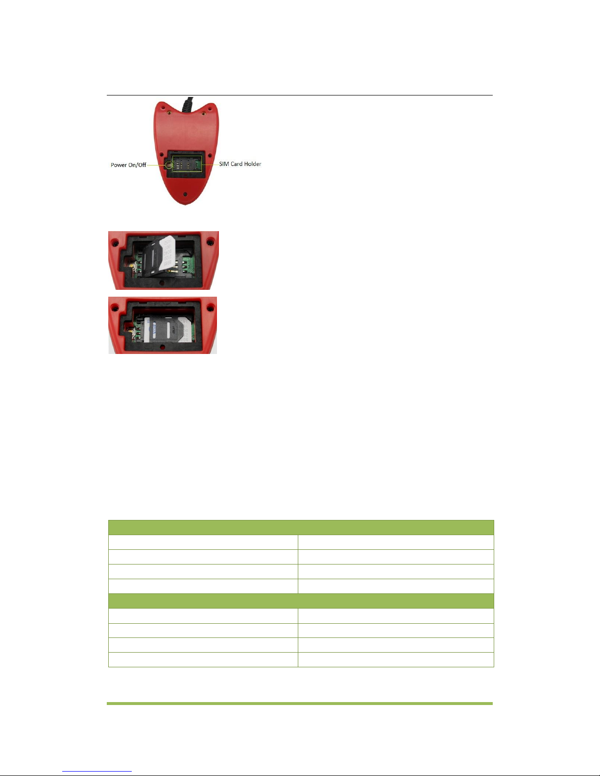
Before installing the SIM card, turn off the power for S4.
S4 with SOS Button
Battery and I/O Cable
3M Sticker Screws
Copyright © 2014 Sonasonic Technologies Private Ltd. All rights reserved.
Unscrew and remove cover.
Insert the SIM card by sliding it into the card holder with the chip module facing to the connectors on PCB.
Replace the cover and screw it up.
6.2 Charging
Please connect GND (-Black) and Power (+Red) wires to 12V or 24 external power and make sure to charge the
battery for at least 3 hours.8 hours is highly appreciated.
Configuration and testing suggested prior to installation.
6.3 LED Indications
Press and hold the Power On/Off button for 3~5 seconds to turn on/off S4
GPS LED (Blue)
On
One button is pressed or input is active.
Flashing ( every 0.1 second)
Initializing or back-up battery power is low
Flashing (0.1 second on and 2.9 seconds off)
S4 has a GPS fix
Flashing (1 second on and 2 seconds off)
S4 has no GPS fix
GSM LED (Green)
On
A call is coming in / a call is being made
Flashing ( every 0.1 second)
Initializing
Flashing (0.1 second on and 2.9 seconds off)
S4 is connected to the GSM network
Flashing (1 second on and 2 seconds off)
S4 is not connected to the GSM network

Copyright © 2014 Sonasonic Technologies Private Ltd. All rights reserved.
6.4 Track by Calling
Make a call to S4 and it will report with one SMS.
For example,
Now,110727 02:48,V,16,23Km/h,61%,http://maps.google.com/maps?f=q&hl=en&q=22.540103,114.082329
&ie=UTF8&z=16&iwloc=addr&om=1
Click on the link then the location can be shown directly on Google Maps on your mobile phone.
Report description:
Now,110727 02:48,V,16,23Km/h,61%,http://maps.google.com/maps?f=q&hl=en&q=22.540103,114.082329
&ie=UTF8&z=16&iwloc=addr&om=1
Content
Description
Note
Now
Current Location
Alarm Type
110721 16:40
Date & Time: 21 July, 2011, 16:40pm
Date & Time in YYMMDD HH:MM
V
No GPS fixed
GPS Status Indicator:
A = valid, V = invalid
10
GSM signal=10
GSM Signal. Decimal Digit (0~31)
0Km/h
Speed=0
KM/h. Decimal digit
97%
Battery Power: 97%
Battery Power Balance (Percentage)
http://maps.google.c
om/maps?f=q&hl=en
&q=22.540103,114.0
82329&ie=UTF8&z=1
6&iwloc=addr&om=1
Latitude: 22.513015
Longitude: 114.057235
Google Maps Web Link with Latitude and
Longitude. Click on the link to get the
location.
If your mobile cannot visit HTTP websites, input the latitude and longitude into Google Maps as the following
picture shows to get the position:
Password is 4 digitsonly and defaulted as 0000. You can change the password by SMS command.
S4 will only accept commands from a user with the correct password and report SMS report to the user. If
preauthorized phone number was set, only this phone number can receive SMS reports.

Copyright © 2014 Sonasonic Technologies Private Ltd. All rights reserved.
7. Installation
7.1 Install I/O Cable
The I/O cable is a 8-pin cable including power, analog input, negative input, output and USB port for
configuration.
7.1.1 Power/GND (PIN1, PIN2)
Connect GND (-Black) and Power (+Red) wires to the battery of motorcycle/vehicle.
1
Power(+)
2
GND(-)
3
GND(-)
4
Input1(-)
5
Input2(+)
6
AD1
7
Out1
8 9 10
USB Port
PIN Color Description
1 Power Red DC In (power source). Input voltage: 9V~36V. 12V suggested.
2 GND Black Ground
3 GND Black Ground, for connecting with temperature/fuel sensor etc.
4 Input1 White Digital Input (negative triggering). Socket for SOS panic button.
It also can be used for detecting the status of vehicle door.
Vehicles from China, Korea, Japan are normally negative triggering.
5 Input2 Purple Digital Input2 (positive triggering). It can be used for detecting ACC,
and the status of vehicle door. Vehicles from Europe, America are
normally positive triggering.
6 AD Blue 12 Bits resolution analog input. 0~6.6V DC detection.
It can be used to connect with fuel sensor etc.
7 Out Yellow Output. Low voltage (0V) when effective and open drain when
ineffective.
Output open drain sink voltage (ineffective): 45V max.
Output low voltage sink current (effective): 200mA max.
It can be used to connect with relay for engine immobilization.
8/9/10 USB Port
(For Configuration Only)
Green TTL232 Rx (S4 Tx)
Orange TTL232 Tx (S4 Rx)
Black Ground

Copyright © 2014 Sonasonic Technologies Private Ltd. All rights reserved.
7.1.4 Output (PIN7)
7.1.2 Digital Input (PIN 3,Negative Triggering)/SOS
7.1.3 Digital Input (PIN5, Positive Triggering)
Copyright © 2014 Sonasonic Technologies Private Ltd. All rights reserved.
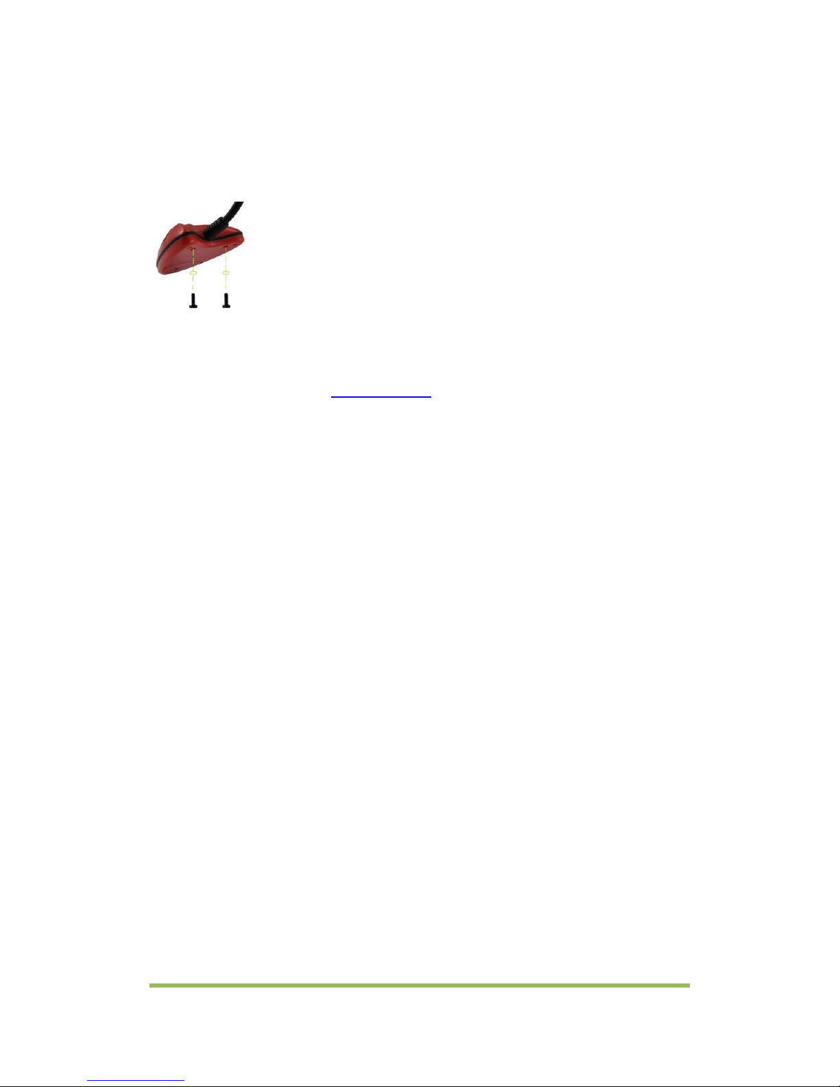
7.2 Mount the S4 unit
Three mounting options:
Option 1:
Using 3M sticker
Option 2:
Using Screws
Option 3:
Using internal super magnet
Please do not hesitate to email us at info@sonasonic.com if you have any questions.
Table of contents


