Sonder Siesta-TA RF User manual

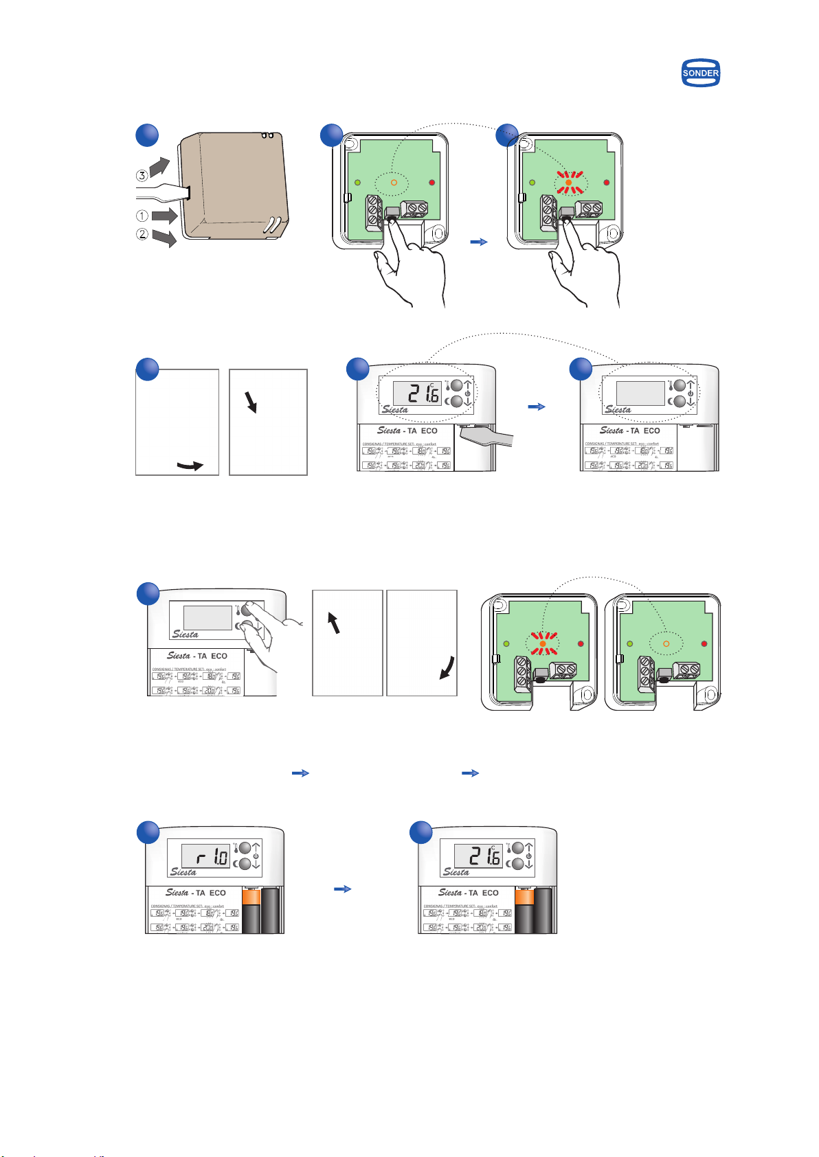
Open battery compartment cover & insert two LR03 AAA 1.5V batteries.
Make sure the positive and negative ends are facing the correct
direction, as shown picture of side & always introducing them as
indicated. The display shows for 2 seconds the program version and
then goes to see the room temperature.
Very Important: Don´t use rechargeables batteries
Digital Radio Thermostat
SONDER
Guarantee conditions
Cod.: 7453 INGVØOCT14
Sonder Regulación, S.A.
Avda. La Llana, 93
08191 RUBÍ
(Barcelona) Spain
www.sonder.es
This appliance has a three-years guarantee limited to
replacement of defective parts. Transport not included.
We will not accept any responsibility for damage caused to
the appliance by poor handling.
The guarantee does not include:
- Appliances with a damaged, effaced or altered series
number.
- Appliances which have not been connected or used
following the instructions that accompany it.
- Appliances which have been altered without the prior
consent of the manufacturer.
- Appliances damaged by blows or liquid spills or gaseous
emissions.
Technical data
Measures:
Batteries replacement
Instructions for installation
SONDER
Sonder
Digital Thermostat Heating Via Radio
Emitter
2
Receiver
Install away from conductive elements, metal surfaces,
electrical cables or excessive heat.
yes
no
3 - 7mm
Connections only by
qualified personnel
2
1
Keep away the emitter of any
source of heat or direct light.
Emitter p alkaline battery
Low battery indicator:...................................................
Battery duration:............................................. 2 years, aprox
Regulation scale:............................................ from 5 to 35°C
Receiver power supply:..................................... 230Vac 50Hz
Breakage power (contacts):........................... 16(8)A 250Vac
Transmission frequency:...................................... 868,3 MHz
Ambient temperature:....................... Tmin. 0°C, Tmax. 40°C
Storage temperature:................................... maximum 50°C
% Relativity Humidity operating:.................. from 20 to 85%
Dregee of protection:.................................................... IP20
Action Type According EN 60730:..................................... 1.B
Homologated:.................................................................... CE
Approx. Max. distance Emitter-receiver:.... 90m in free field
ower supply:. 2 1,5V LR03 (AAA)
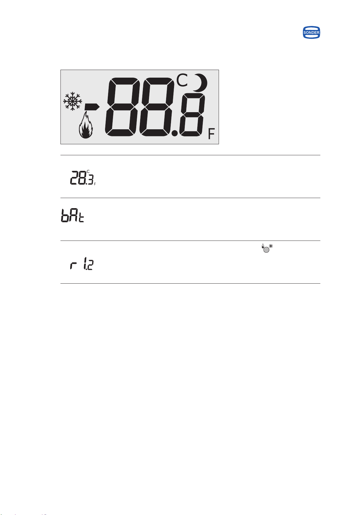
“bAt”
Net weight: 95 g Net weight: 85,5 g
76
30
100
80
20
-TA RF
1
Flexible H-05V-KCable
Max. 9mm
S. 1,5mm
2
12
NO C
3
NC N
5
L
4
230Vac 50Hz
>
Electrical drawing receiver:
eco
Sonder
-TA RF
°
Parameters
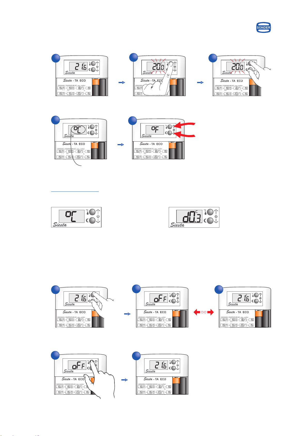
OFF / STOP
Sonder
-TA RF
°
1 s
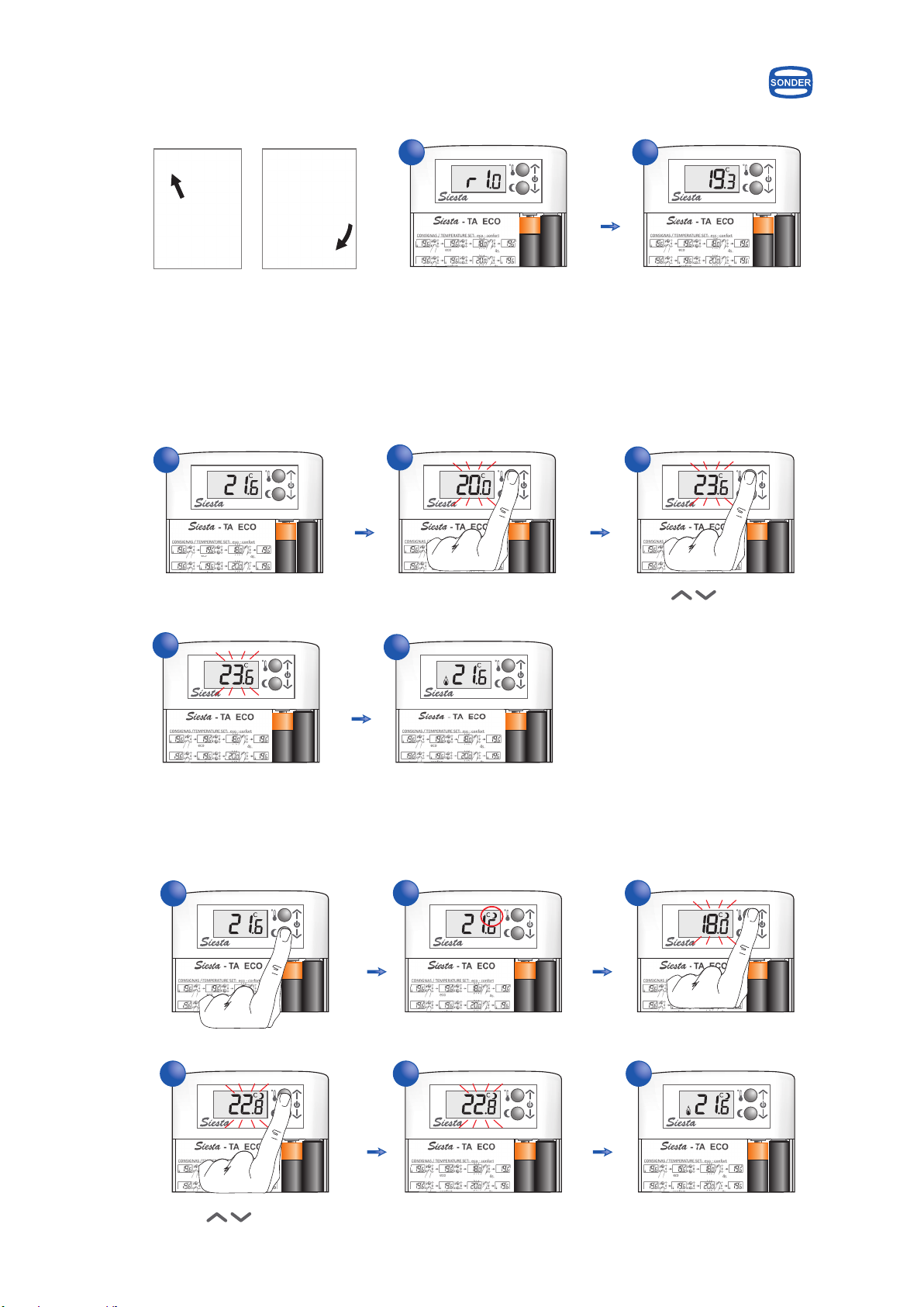
comfort
Double setpoint: comfort / eco
Instructions for use
4 s 4 s
ON - OFF / - START STOP
Enter in the parameter setting menu
Reset
Sonder
-TA RF
°
Sonder
-TA RF
10 s
Sonder
-TA RF Sonder
-TA RF
°
°
Sonder
-TA RF Sonder
-TA RF
°°
1 s
Sonder
-TA RF
4 s
°
Sonder
-TA RF Sonder
-TA RF
°
Sonder
-TA RF
°
Sonder
-TA RF
Sonder
-TA RF
°°
1 s
Sonder
-TA RF
4 s
°
Sonder
-TA RF
°
ON / START
0,1 ... 2°C / 0,2 ... 3,6°F
0,2 ... 2°C / 0,4 ... 3,6°F
OFF or 5 ... 18°C
41 ... 64°F
20 ... 35°C
68 ... 95°F
-3 ... +3°C
-5,4 ... +5,4°F
°C or °F
5 ... 19°C
41 ... 66°F
Differential
Frost protection
Limit max. temperature setpoint
Sensor calibration
Temperature units
Limit min. temperature setpoint
Sonder
-TA RF
Sonder
Sonder
-TA RF
Sonder
-TA RF
°
°
Sonder
-TA RF
Sonder
-TA RF
°
°
°
Sonder
-TA RF
°
Sonder
-TA RF Sonder
-TA RF
°°
1s
Sonder
-TA RF
10s
Sonder
-TA RF
Next parameter
Change the value
Regulation mode: Heating / Cooling
Heating
1 s
Sonder
-TA RF
Sonder
-TA RF
°
Sonder
-TA RF
Siesta-TA ECO RF model
Cooling
4 s
Sonder
-TA RF Sonder
-TA RF
°
Siesta-TA ECO RF has the frost protection fix to 5°C & no have:
- Regulation in cooling mode
- The parameters: Setpoints limits and sensor calibration
- Reset
Sonder
-TA RF
°
Sonder
-TA RF
1 s
Sonder
-TA RF
°
Direct Link: http://www.sonder-regulacion.com/manuales/Manual_Siesta-TA_RF_Siesta-TA_ECO_RF_Avanzado_Ingles.pdf
In our technical web
complete manual with detailed instructions
(www.sonder-regulacion.com), may find the
Programation & activation of functions
-TA RF
Digital Radio Thermostat
SONDER
Digital Thermostat Heating Via Radio
VERY IMPORTANT:
This appliance should be mounted on a
universal embedded box.
Device designed for a clean pollution
situation.
This control is not a safety device and should
not be used as such, is the responsibility to
incorporate appropriate protection for each
type of facility (homologated) installer.
Independent control device mounting, and
connection via fixed pipeline.
We reserve the right of modify without
prior notice.

New Programming
New Display
New Heart
Energy Control
Model Siesta - TA RF / TA ECO RF
Digital Radio Thermostat
Generation CorteX
Instructions Manual
Siesta -T A
Family

INDEX
Description
Technical data
Location
Installation
Batteries replacement
First connection
Double setpoint: eco / comfort
Display information
Parameters
On / Off - Start / Stop
Reset
Coding between emitter and receiver
Regulation mode: Heating / Cooling
2
3
3
4
4
5
5
6
8
9
9
9
10
Siesta - TA
Energy Control
Siesta - TA ECO
Guarantee conditions
Description
Technical data
Location
Installation
Batteries replacement
First connection
Double setpoint: eco / comfort mode
Display information
Parameters
On / off - Start / Stop
Coding between emitter and receiver
11
12
12
13
13
14
14
15
16
16
17
18

Description
2
Energy Control
Emitter
Receiver
Forced manual button, turns on and off relay checking the
operation of the installation
Wire connectors for electrical connection of the receiver
(only by qualified personnel & according to the diagram)
It is a digital thermostat for heating or cooling battery powered for residential use, and communicating via
radio (wireless). Factory has recorded the values of the parameters as default, you can modify as indicated
on page 8.
Note: Emitter and receiver are encoded factory, if you need to recode see how to do it on page 10.
Input parameters,
advancing parameter
Value changes, ON / OFF &
encoding emitter - receiver
Key comfort mode
Key eco mode
Sonder
-TA RF
º
Internal key mode
heating / cooling
and reset
Red LED on - plugged in
Red LED off - unplugged
Green LED on - relay status on
Green LED off - relay status off
Green LED flashing - change in the relay state
Orange LED on - has communication with the emitter
Orange LED off - has no communication with the emitter
Orange LED flashing - receiving an order

Energy Control
:............................................... from 5 to 35°C
1.5V alkaline battery (2 pcs.):................................. LR03 (AAA)
Low battery indicator:..................................................... “bAt”
Battery duration:............................................. 2 years, approx
Net weight (with batteries):............................................... 95 g
Regulation scale
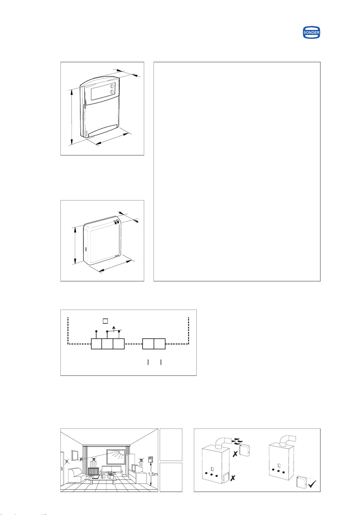
Technical data
Emitter measures mm
Receiver measures mm
Specifications
3
76
76
30
100
80
20
Electrical drawing Siesta-TA
Emitter
Power supply:....................................................... 230Vac 50Hz
Breakage power (contacts):............................... 16(8)A 250Vac
2
Maximum cable to connect:........................................ 1,5mm
Wiring type:................................................................ H-05V-K
Net weight:..................................................................... 85,5 g
Receiver
Transmission frequency:..........................................868,3 MHz
Approx. Max. distance Emitter-receiver:...... 90 m in free field
Ambient temperature:.......................... Tmin. 0°C, Tmax. 40°C
Storage temperature:...................................... maximum 50°C
% Relative Humidity operating:....................... from 20 to 85%
Dregree of protection:....................................................... IP20
Dregree of pollution:.............................................................. 2
Software:....................................................................... Class A
Action type According EN 60730:........................................ 1.B
Homologated:....................................................................... CE
Gross weight:................................................................... 203 g
Both
Location
Emitter - Keep away the emitter of any source of
heat or direct light.
Receiver - Install away from conductive elements,
metal surfaces, electrical cables or
excessive heat.
yes
no
2
1
1
2
12
NO C
3
NC N
5
L
4
230Vac 50Hz
>
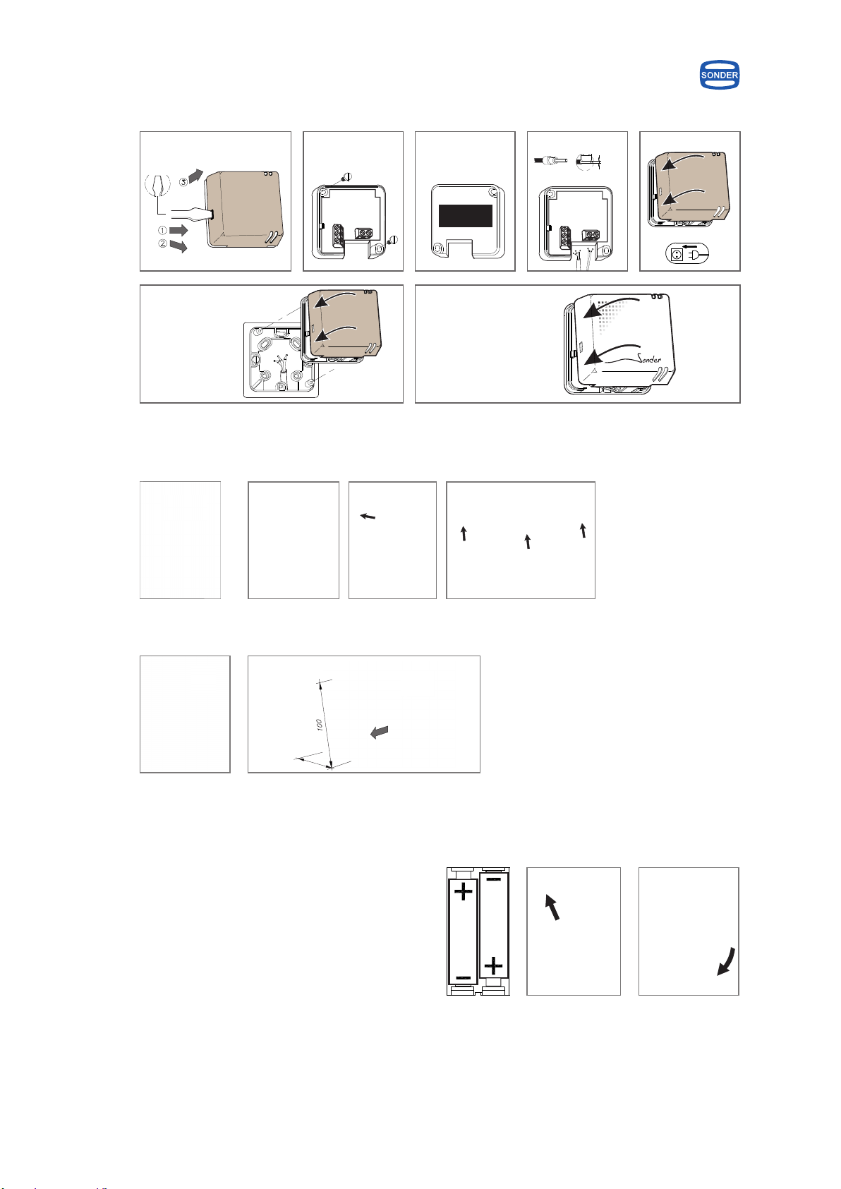
Batteries replacement
Open battery compartment cover & insert two
LR03 AAA 1.5V batteries. Make sure the positive
and negative ends are facing the correct direction,
as shown picture of side & always introducing them
as indicated. The display shows for 2 seconds the
program version and then goes to see the room
temperature.
Very Important: Don´t use rechargeables batteries
Emitter
Installation
3 - 7mm
Flexible cable H-05V-K
Max. 9mm
S. 1,5mm
2
Receiver
2 - Support to put over table
Adhesive or
double sided velcro
(not included)
Wall installation by
screw
Connections only by qualified
personnel
UP
mm
mm
60
click!!
Energy Control
click!!
Optional accessory
PLACA TA
Code: 3.970
Optional accessory
PEANA
Code: 4.965
click!!
4
1 - Wall installation
click!!
Optional accessory
CAPOT BLANCO RADIO
Code: 5.710

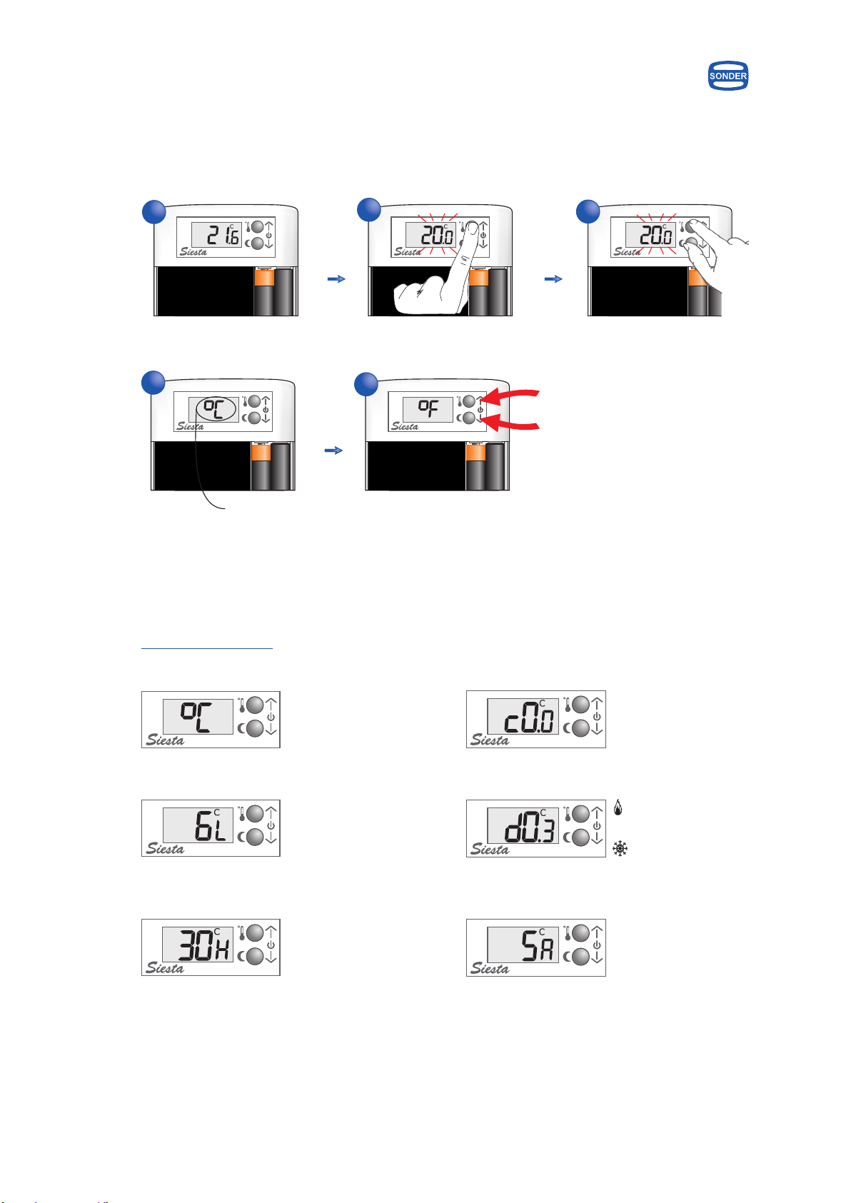
First connection
Version
5
Energy Control
Ambient Temperature
Double setpoint: eco / comfort
Temperature change for comfort setpoint
Temperature change for eco setpoint
1
Sonder
-TA RF Sonder
-TA RF
2
º
1 s
Sonder
-TA RF
º
Sonder
-TA RF
º
1 s
Sonder
-TA RF
º
Sonder
-TA RF
º
Sonder
-TA RF
º
Sonder
-TA RF
º
Sonder
-TA RF
º
4 s
Sonder
-TA RF
º
Sonder
-TA RF
º
Sonder
-TA RF
º
Sonder
-TA RF
º
4 s
123
45
1
1S
3
4
2
5 6

Display information
6
Energy Control
º
º
Manual off The device no control the temperature, only remains the Frost
protection function.
Regulation in heating Relay switched on when the temperature is below the setpoint
minus differential & relay switched off when arrives to setpoint.
Pressing the internal key displays the current mode control
and double-clicking change the mode.
Regulation in cooling Relay switched on when the temperature is above the setpoint
plus differential & relay switched off when arrives to setpoint.
Pressing the internal key displays the current mode control
and double-clicking change the mode.
Display shown when the boiler or regulation pump is activated in
heating mode.
Activated relay
Digits The display shows by digits the reading ambient temperature.
º
Flashing digits The display shows by flashing digits the setpoint for comfort
temperature.
º
Display shown when the boiler or regulation pump is activated in
cooling mode.
Activated relay
Digits & Moon The display shows by flashing digits and moon the setpoint for
eco temperature.
º
Display information
7
Energy Control
º
º
Reset Pressing by 10 seconds the internal key deletes the custom
settings of the parameters and return to the factory settings.
Indicates the batteries status is low and should be changed.
Batteries
Temperature in °C / °F On the screen you can see next to the temperature in what
magnitude is measured: degrees Celsius (°C) or degrees
Fahrenheit (°F).
º
º
8
Energy Control
Sonder
-TA RF
Sonder
Sonder
-TA RF
Sonder
-TA RF
º
º
Sonder
-TA RF
Sonder
-TA RF
º
º
º
-TA RF
1 s
Sonder
-TA RF
º
Sonder
-TA RF
º
Sonder
-TA RF
º
Sonder
-TA RF
Sonder
-TA RF
Scale: °
°
20 ... 35 C
68 ... 95 F
Limit maximum temperature setpoint
Scale: -3.0°C ... +3.0°C
-5.4°F ... +5.4°F
Sensor calibration
Scale: °
°
5 ... 19 C
41 ... 66 F
Scale: OFF / ON
5 ... 18°C
41 ... 64°F
Frost protection
Limit minimum temperature setpoint
Scale: °
°
0,2 ... 2 C
0,4 ... 3,6 F
10 s
Parameters
Enter the parameter setting menu
Scale: °
°
0,1 ... 2 C
0,2 ... 3,6 F
Differential activation
Scale: Celsius °C
Fahrenheit °F
Temperature units
Factory
set value
Adjustable parameters
Advance to the next parameter
Change the setting
123
45

9
Energy Control
Reset
On - Off / Start - Stop
Regulation mode: Heating / Cooling
Off / Stop
On / Start
Heating Cooling
Sonder
-TA RF
º
Sonder
-TA RF Sonder
-TA RF
º
123
10 s
1 s
4 s
Sonder
-TA RF
º
Sonder
-TA RF Sonder
-TA RF
º
Sonder
-TA RF
º
Sonder
-TA RF
123
12
4 s
1 s
Sonder
-TA RF
º
Sonder
-TA RF Sonder
-TA RF
Sonder
-TA RF
Sonder
-TA RF
123
45
4 s
º
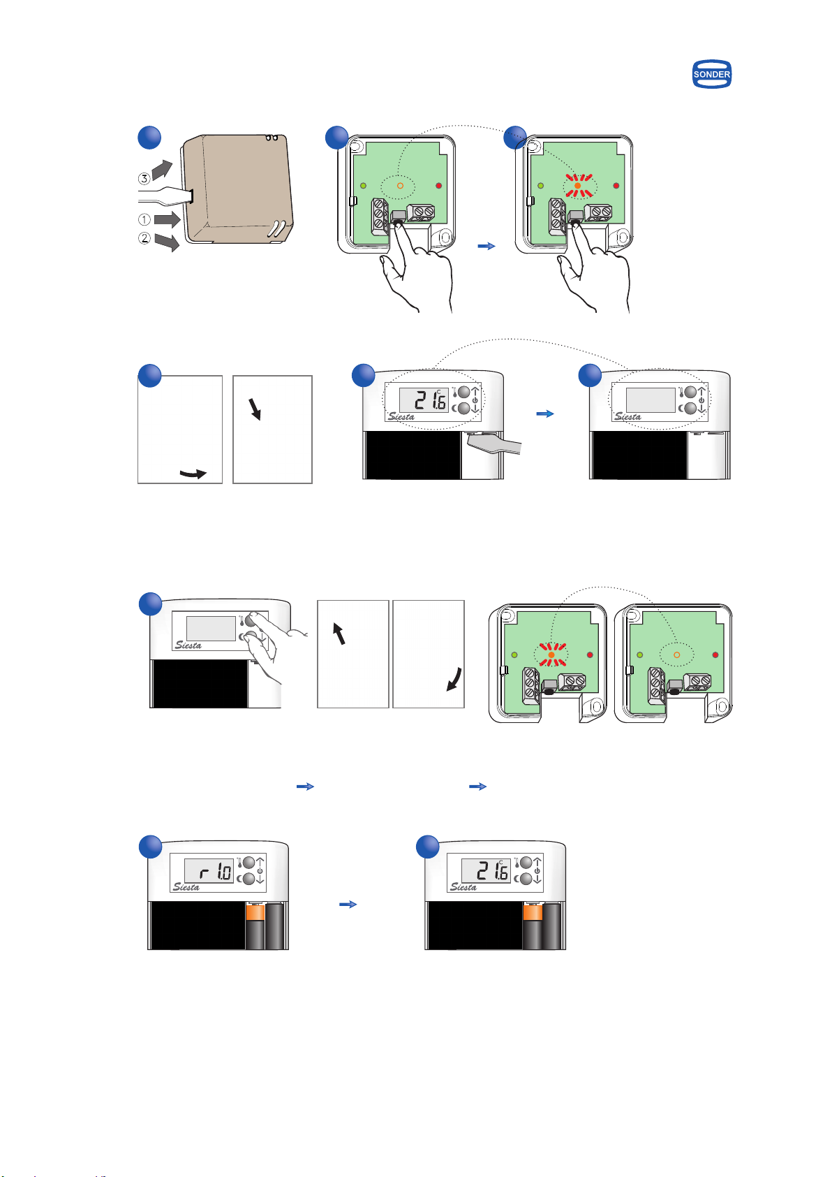
Coding between emitter and receiver
10
Energy Control
Until
Remove batteries
Hold down Put batteries Until
1
5 6
7
4
23
8
Sonder
-TA RF
Sonder
-TA RF
º
Sonder
-TA RF
Sonder
-TA RF
9
Sonder
-TA RF
º

Description
11
Energy Control
Emitter
Receiver
It is a digital thermostat for heating battery powered for residential use, and communicating via radio
(wireless). Factory has recorded the values of the parameters as default, you can modify as indicated on
page 16.
Note: Emitter and receiver are encoded factory, if you need to recode see how to do it on page 17.
Sonder
-TA RF
º
ººº
Siesta
- TA ECO
CONSIGNAS / TEMPERATURE SET: eco - confort
º
1 s.
eco
ºº º
4s.
4s.
confort
Forced manual button, turns on and off relay checking the
operation of the installation
Wire connectors for electrical connection of the receiver
(only by qualified personnel & according to the diagram)
Red LED on - plugged in
Red LED off - unplugged
Green LED on - relay status on
Green LED off - relay status off
Green LED flashing - change in the relay state
Orange LED on - has communication with the emitter
Orange LED off - has no communication with the emitter
Orange LED flashing - receiving an order
Key comfort mode
Key eco mode
Input parameters,
advancing parameter
Value changes, ON / OFF &
encoding emitter - receiver
1
T
2
NO C
Heating
- °C
3
NC N
5
L
4
230Vac 50Hz
Energy Control
:............................................... from 5 to 35°C
1.5V alkaline battery (2 pcs.):................................. LR03 (AAA)
Low battery indicator:..................................................... “bAt”
Battery Duration:............................................. 2 years, approx
Net weight (with batteries):............................................... 95 g
Regulation scale
Technical data
Emitter measures mm
Receiver measures mm
Specifications
12
76
76
30
100
80
20
Electrical drawing Siesta-TA
Emitter
Power supply:....................................................... 230Vac 50Hz
Breakage power (contacts):............................... 16(8)A 250Vac
2
Maximum cable to connect:........................................ 1,5mm
Wiring type:................................................................ H-05V-K
Net weight:..................................................................... 85,5 g
Receiver
Transmission frequency:..........................................868,3 MHz
Approx. Max. distance Emitter-receiver:...... 90 m in free field
Ambient temperature:.......................... Tmin. 0°C, Tmax. 40°C
Storage temperature:...................................... maximum 50°C
% Relative Humidity operating:....................... from 20 to 85%
Dregree of protection:....................................................... IP20
Dregree of pollution:.............................................................. 2
Software:....................................................................... Class A
Action type According EN 60730:........................................ 1.B
Homologated:....................................................................... CE
Gross weight:................................................................... 203 g
Both
Location
Emitter - Keep away the emitter of any source of
heat or direct light.
Receiver - Install away from conductive elements,
metal surfaces, electrical cables or
excessive heat.
yes
no
2
1
1
2

Batteries replacement
Emitter
Installation
3 - 7mm
Flexible cable H-05V-K
Max. 9mm
S. 1,5mm
2
Receiver
2 - Support to put over table
Adhesive or
double sided velcro
(not included)
Wall installation by
screw
Connections only by qualified
personnel
UP
mm
mm
60
click!!
Energy Control
click!!
Optional accessory
PLACA TA
Code: 3.970
Optional accessory
PEANA
Code: 4.965
click!!
13
1 - Wall installation
click!!
Optional accessory
CAPOT BLANCO RADIO
Code: 5.710
Open battery compartment cover & insert two
LR03 AAA 1.5V batteries. Make sure the positive
and negative ends are facing the correct direction,
as shown picture of side & always introducing them
as indicated. The display shows for 2 seconds the
program version and then goes to see the room
temperature.
Very Important: Don´t use rechargeables batteries
Energy Control
14
First connection
Version Ambient temperature
Double setpoint: eco / comfort
Temperature change for comfort setpoint
Temperature change for eco setpoint
1
4 s
Sonder
-TA RF Sonder
-TA RF
2
º
1 s
Sonder
-TA RF
º
Sonder
-TA RF
º
1 s
Sonder
-TA RF
º
Sonder
-TA RF
º
Sonder
-TA RF
º
Sonder
-TA RF
º
Sonder
-TA RF
º
4 s
Sonder
-TA RF
º
Sonder
-TA RF
º
Sonder
-TA RF
º
Sonder
-TA RF
º
4 s
123
45
1
1 s
3
4
2
5 6
15
Energy Control
º
º
Display shown when the boiler or regulation pump is activated
in heating .
Activated relay
º
º
º
Indicates the battery status is low and should be changed.
Batteries
Temperature in °C / °F On the screen you can see next to the temperature in what
magnitude is measured: degrees Celsius (°C) or degrees
Fahrenheit (°F).
º
º
Display information
Manual off The device no control the temperature, only remains the Frost
protection function.
Digits The display shows by digits the reading ambient temperature.
Flashing digits The display shows by flashing digits the setpoint for comfort
temperature.
Digits & Moon The display shows by flashing digits and moon the setpoint for
eco temperature.
Parameters
16
Energy Control
Enter the parameter setting menu
Sonder
-TA RF Sonder
-TA RF
º
Scale: °
°
0,5 ... 1 C
0,3 ... 1,8 F
Differential activation
Scale: Celsius °C
Fahrenheit °F
Temperature units
Factory
set value
Adjustable parameters
Advance to the next parameter
Change the setting
On - Off / Start- Stop
Off / Stop
On / Start
Frost protection - Fix to 5°C
1 s
Sonder
-TA RF
º
Sonder
-TA RF
º
Sonder
-TA RF
º
Sonder
-TA RF
Sonder
-TA RF
123
45
10 s
1 s
4 s
Sonder
-TA RF
º
Sonder
-TA RF Sonder
-TA RF
º
Sonder
-TA RF
º
Sonder
-TA RF
123
12
4 s
17
Energy Control
Coding between emitter and receiver
Until
Remove batteries
Hold down Put batteries Until
1
56
7
4
Energy Control
2 3
8
Sonder
-TA RF
Sonder
-TA RF
º
Sonder
-TA RF
Sonder
-TA RF
9
Sonder
-TA RF
º
Guarantee conditions
First of all thank you for the purchase and trust
placed in the team. We hope that the thermostat
Siesta meets the needs of your installation.
- Before installing the thermostat make sure that
environmental conditions are suitable,
temp eratu re, h umidity, pollution an d
greenhouse gas emissions, and that any of these
factors may affect the efficient operation
- The device is an independent control device for
surface mounting on a universal embedded box,
and type 2 dry environment pollution.
- For any work, either as installation or repair, the
regulator must be disconnected from the power
supply.
- Electrical connections may only be indicated in
this manual and on the sticker on the back of the
cap connections.
- This controller is not a safety device or can be used
as such, is responsible incorporate appropriate
protection for each type of facility (homologated)
by the installer.
- Installation, electrical connection, commissioning
and maintenance must be performed only by
qualified personnel.
- If visualize possible defects that could cause
damage or malfunction in the system, do not
connect the appliance.
- Forbidden the total or partial reproduction of this
document by any means without prior written
authorization of Sonder Regulación S.A.
- The graphics and information in this manual are
indicative only and may include technical
inaccuracies or typographical errors.
- Sonder Regulación S.A. reserves the right to make
changes to the product, technical data, or
instructions for assembly and use without notice.
This device has 3 year warranty, it is limited to
replacement of the defective part and will be
delivered in the same material reception
conditions, packaging, batteries, instructions or
any other accessory that includes this product will
not be replaced and not be noted in the packing
slip.
We decline any responsibility for damage caused
to the appliance by bad handling, failure to follow
instructions contained in this manual or technical
ignorance of the needs of the installation.
For repairs under warranty must present the
documentation that accredits purchase of the
device within the validity period of this warranty
and as accurate a description as possible of the
defect or anomalous behavior of the product
according to the user.
If the repair is out of warranty, it will inform the
user of the viability and cost of it. The valuation of
our technical department may be an additional
cost to the user.
Are out of guarantee:
! Devices with serial number deteriorated,
deleted or modified.
! Devices whose connection or use have not been
implemented in accordance with the attached
to the appliance.
! Devices modified without prior agreement with
the manufacturer.
! Devices damaged by blows or liquid or gaseous
emanations.
! Devices with natural wear or improper use of
equipment.
! The costs resulting from the sending or receipt
of material.
! The demands for damages on account of loss of
profits, compensation for use, & consequential
damages. Provided that these damages are not
mandatory liability under the law.
Sonder Online Shop www.sonder.es
Technical Information www.sonder-regulacion.com Energy Control
18
Cód.: 7454VØOCT14
Note: Translation is informative, the only legally binding document is the written version of it in Spanish.
UNE-EN 60730-1 + A1:2005 + A12:2004 + A13:2005
UNE-EN 60730-2-1: 1998 + A11:2005
MADE IN
SPAIN
Designed and manufactured by Sonder in Rubi as:
This manual suits for next models
1
Table of contents
Other Sonder Thermostat manuals

Sonder
Sonder Siesta 105 WiFi User manual

Sonder
Sonder Siesta-TA ECO RF User manual

Sonder
Sonder Siesta 105 WiFi User manual

Sonder
Sonder Siesta - CRX Series User manual

Sonder
Sonder Siesta 105 WiFi User manual

Sonder
Sonder RAIL 322 User manual

Sonder
Sonder Siesta CRX RD Radiante User manual

Sonder
Sonder Siesta -TA Series User manual

Sonder
Sonder Siesta 105 WiFi User manual


