Sonel LKZ-1500 User manual


USER MANUAL
CABLES AND UNDERGROUND
INFRASTRUCTURE LOCATOR
LKZ-1500-LITE
LKZ-1500
SONEL S.A.
Wokulskiego 11
58-100 Świdnica
Version 2.00 12.10.2021

LKZ-1500-LITE ● LKZ-1500 –USER MANUAL
2
Locator LKZ-1500 is a modern, high quality measuring device, easy and safe to use. Reading and us-
ing of this manual will help to avoid errors in measurements and prevent possible problems when op-
erating the instrument.

LKZ-1500-LITE ● LKZ-1500 –USER MANUAL
3
TABLE OF CONTENT
1Safety ................................................................................................................5
2Description of the system...............................................................................6
3LKN-1500 transmitter ......................................................................................6
3.1 Operating principle of the transmitter LKN-1500......................................................7
3.2 Design and front panel of the transmitter ................................................................. 7
3.3 Safety measures ...................................................................................................... 8
3.4 Operating the transmitter..........................................................................................9
3.4.1 Signaling of the status and modes of operation of the transmitter......................................9
3.4.2 Direct connection –galvanic mode..................................................................................10
3.4.2.1 Connecting the transmitter to the object....................................................................10
3.4.2.2 Signal frequency selection ........................................................................................10
3.4.2.3 Signal power output settings.....................................................................................11
3.4.2.4 Transmitter operation mode selection .......................................................................11
3.4.2.5 Voltage output limitation............................................................................................12
3.4.3 Non-contact survey current generation in communication line.........................................12
3.4.3.1 Internal transmitter inductor.......................................................................................12
3.4.3.2 Inductive clamps.......................................................................................................13
4LKO-1500-LITE / LKO-1500...........................................................................14
4.1 Principles of operation............................................................................................ 14
4.2 Design and front panel of the receiver ................................................................... 14
4.3 Operating the receiver............................................................................................ 18
4.4 Selection and setting the main parameters via Menu options ................. 18
4.5 Operating modes of the receiver............................................................. 21
4.6 Locating methods................................................................................................... 23
4.6.1 Selection of operating frequency.....................................................................................23
4.6.2 Peak, null and current direction modes............................................................................23
4.6.2.1 Peak mode................................................................................................................24
4.6.2.2 Peak search with 1:4 scale .......................................................................25
4.6.2.3 The null method........................................................................................................26
4.6.2.4 Locating with “Compass line” option .........................................................27
4.6.2.5 Locating by current direction.....................................................................29
4.6.3 Depth and current intensity of the utilities........................................................................30
4.6.3.1 Measurement of depth..............................................................................................31
4.6.3.2 Measurement of current............................................................................................31
4.6.3.3 Indirect 6 dB test method for depth measurement.....................................................32
4.6.3.4 Locating by the utility current.....................................................................................33
4.7 Testing of ground plots........................................................................................... 34
4.7.1 Passive locating without Transmitter ...............................................................................34
4.7.2 Testing of ground plots with LKN transmitter...................................................................35
4.7.2.1 One-man test method ...............................................................................................35
4.7.2.2 Two-man test method ...............................................................................................36
5Methods of locating damaged pipelines and utilities ................................37
5.1 Fault finding with leakage current........................................................................... 37
5.2 Fault finding with insulation control sensors –DKI-E or A-frame................. 37
5.2.1 Insulation fault finding by signal drop...............................................................................38
5.2.2 The search of the insulation failure by the signal rise ......................................................39
5.2.3 Cable breakdown location...............................................................................................40

LKZ-1500-LITE ● LKZ-1500 –USER MANUAL
4
5.2.3.1 Finding of short-circuited conductors.........................................................................40
5.2.3.2 Location of shorted conductor-shield positions..........................................40
5.2.3.3 Tracing of damaged insulation and grounding area...................................41
6Data storage, GPS navigation.........................................................42
6.1 Adjustment of the Receiver to the GPS modules................................................... 43
6.2 Track recording...................................................................................................... 44
6.2.1 Recording with button .....................................................................................................44
6.2.2 Auto tracking...................................................................................................................44
6.2.3 Log..................................................................................................................................45
6.2.4 Distance..........................................................................................................................45
6.2.5 Transmission to PC.........................................................................................................45
7Power supply..................................................................................................46
7.1 LKN-1500 power supply......................................................................................... 46
7.2 LKO-1500-LITE / LKO-1500 power supply............................................................. 46
8Possible faults and troubleshooting............................................................47
8.1 LKO-1500 transmitter............................................................................................. 47
8.2 LKO-1500-LITE / LKO-1500 receiver..................................................................... 47
9Maintenance and running repairs ................................................................48
10 Transportation and storage..........................................................................48
11 Dismantling and utilization...........................................................................48
12 Technical data................................................................................................49
12.1 LKN-1500 transmitter............................................................................................. 49
12.1.1 Basic technical data........................................................................................................49
12.1.2 Other technical data........................................................................................................50
12.2 LKO-1500-LITE / LKO-1500 receiver..................................................................... 50
12.2.1 Basic technical data........................................................................................................50
12.2.2 Other technical data........................................................................................................51
13 Accessories....................................................................................................52
13.1 Standard accessories............................................................................................. 52
13.2 Optional accessories.............................................................................................. 52
14 Service ............................................................................................................53
15 Laboratory services.......................................................................................54

LKZ-1500-LITE ● LKZ-1500 –USER MANUAL
5
1 Safety
To ensure adequate service and correctness of the results obtained, the following recommenda-
tions must be observed:
Please read this manual thoroughly before using the set, and follow the safety regulations and
manufacturer's instructions.
Any use of the kit other than those specified in this manual, may result in a damage to the device
and will be a source of serious danger to the user.
The LKZ-1500 kit can only be used by qualified persons with the required electrical work permit.
Using the kit by unauthorized persons may damage the device and cause serious danger to the
user.
The use of this manual does not exclude the necessity of observing safety rules and other rele-
vant regulations required for the performance of given kinds of work. It is essential to consult a
person responsible for health and safety at work, before working with equipment in unsafe condi-
tions, for example in dangerous atmosphere which may cause explosion or fire.
It is unacceptable to use a tool that has been damaged and is totally or partially inoperable, e.g.
with damaged cables or stored for long periods of time in poor conditions.
Do not leave the transmitter connected to the object unattended.
Do not disconnect the wires from the object while the transmitter is operating.
Repairs may only be carried out by an authorized service center.
WARNING
Disconnecting the protective conductor is a serious life threat for executives and
outsiders. Wherever possible, disconnect the mains voltage and the phase conduc-
tor (conductors) as soon as possible. Take special care when disconnecting the
protective conductor or grounding of the neutral conductor from the system that
must be live. Ensure that no outsiders are present in the danger area. Once the lo-
cation is complete, it is essential to restore the protective earth conductor.
NOTE!
The LKN-1500 transmitter is designed for use on non-voltage objects. Connecting to a
230 V network may cause damage. The transmitter generates dangerous voltage up to
250 V.
Please read this manual before turning on the transmitter.
Due to the continuous development of the device software, the appearance of the dis-
plays for some functions may be slightly different than those shown in this manual.
Due to a continuous development of the product and the implementation of the chang-
es, in order to increase reliability and improve working conditions, there are slight differ-
ences between the product and the description of its construction in this user manual.
LKZ-1500-LITE ● LKZ-1500 –USER MANUAL
6
2 Description of the system
The LKZ-1500 locator system consists of an LKO-1500 receiver and an LKN-1500 transmitter kitted
as follows:
LKZ-1500-LITE is a kit of LKN-1500 with LKO-1500-LITE;
LKZ-1500 is a kit of LKN-1500 with LKO-1500.
The system allows to track a route of the underground objects like:
Electrical wires and power cables,
Control and telecommunication lines,
Lightning protection and cathodic protection,
water and sewage installations,
heating systems and pre-insulated pipes,
other metal objects that can conduct electricity.
The icon with the meter name is placed next to sections of the text that refer to specific fea-
tures of the device. All other parts of the text relate to all types of the instrument.
3 LKN-1500 transmitter
The transmitter is designed for generating and transmitting signals in the line under study, and to-
gether with the LKO receiver, it allows to locate the track, determine the burial depth of object, as well
as the location of insulation damage, e.g. cables or pipelines. Current output waveform for LKN-1500
is modified sine wave.
The transmitter can cooperate with any LKO receiver that has the same frequency. Transmitters
are powered by integral maintenance-free sealed accumulator. External 12 V 7 Ah DC source is al-
lowed for use to provide the required power.
Supply voltage self-check system of transmitter indicates its reduction in the range from 11.0 to
10.5 V. If the supply voltage drops between 10.0 and 10.5 V, the transmitter shuts down automatical-
ly.
NOTE!
Periodically recharge the battery to the nominal charge voltage. A deep battery drain
(which is less than 10 V) which may occur during prolonged storage will irreversibly dam-
age the battery, which will require its replacement.
The transmitter’s accumulator charging mode is activated automatically when connecting power sup-
ply unit. Transmitter provide accumulator overcharge protection. The transmitter can operate in 3 sig-
nal generation modes:
a) continuous wave generation;
b) pulsing generation ⅔ (signal generation – 1 sec, pause –0.5 sec);
c) pulsing generation ½ (signal generation – 0.5 sec, pause 0.5 sec).

LKZ-1500-LITE ● LKZ-1500 –USER MANUAL
7
3.1 Operating principle of the transmitter LKN-1500
Operating principle of the transmitter is based on DC source energy conversion to AC signal. So,
the transmitter microprocessor produces control pulses. Microprocessor also controls transmitter’s
conditioning by load to provide maximum power output. The transmitter operation and status infor-
mation is presented on front panel display.
3.2 Design and front panel of the transmitter
Fig. 1 Design of the LKN-1500 transmitter
Fig. 2 Front panel of LKN-1500 transmitter
LKZ-1500-LITE ● LKZ-1500 –USER MANUAL
8
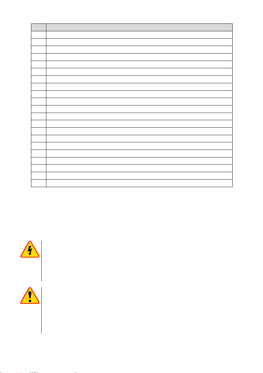
Tab. 1 Description of the control panel and display of LKN-1500 transmitter
No.
Description
1.
Transmitter on / off button
2.
Power supply unit connector for integral accumulator charging or operation from a boost battery
3.
Power output decrease button
4.
Power output increase button
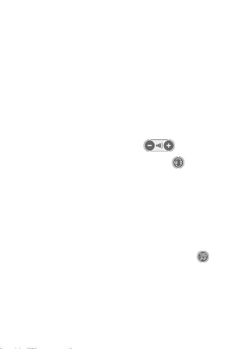
5.
Indication of power output
6.
Current output (A) or voltage (V) indicator
7.
The symbol of internal inductor’s signal
8.
The symbol of signal passing through “Output” sockets
9.
External power source status indicator (symbol)
10.
Internal accumulator status indicator (symbol)
11.
Displayed parameter selection button: value of the output current [A] or voltage [V]
12.
Transmitter output signal condition
13.
Output” sockets for load connection
14.
Socket for connection of grounding probe
15.
“Generation mode” button is used to set continuous wave or pulsing generation mode (see pos. 3)
16.
Option button for signal transmission: induction or direct galvanic connection
17.
Indication symbols of internal accumulator charging process
18.
Button for selecting the signal type: double / single
19.
Double-frequency selection indicators
20.
Signal frequency selection button
21.
Indicators of specified frequency rates
3.3 Safety measures
The transmitter shall be operated in compliance with electrical safety requirements by skilled per-
sonnel who learned this operation manual and have the required electrical safety access qualification
level.
WARNING
During operation voltage output level across “Output” sockets and connected
circuits may reach 240 V. In operating condition avoid contact with conductive
parts connected to the transmitter.
The transmitter shall be switched off during connection to and disconnection
from the examined line or object.
NOTE!
Before operation check the status of “Output” sockets, the surface around them, and
clean if needed. Do not use the transmitter and its component parts in the event of me-
chanical damage. During operation prevent moisture getting into the transmitter panel
and/or power supply unit and use it in accordance with the instruction manual.
Do not expose to direct sunlight in summer season in order to avoid transmitter over-
heating.
LKZ-1500-LITE ● LKZ-1500 –USER MANUAL
9
3.4 Operating the transmitter
The transmitter shall be maintained at operating temperature within two hours in case it was
stored at a different temperature before.
Switching on and off the transmitter is done by pressing the button (see p. 1 on Fig. 2). Af-
ter switching on, the transmitter sets the minimum output power and frequency at 273 [Hz], but the
output voltage level is not limited. The transmitter display reads the transmitter’s operating mode and
the internal battery status or the external power supply status. See also Tab. 2.
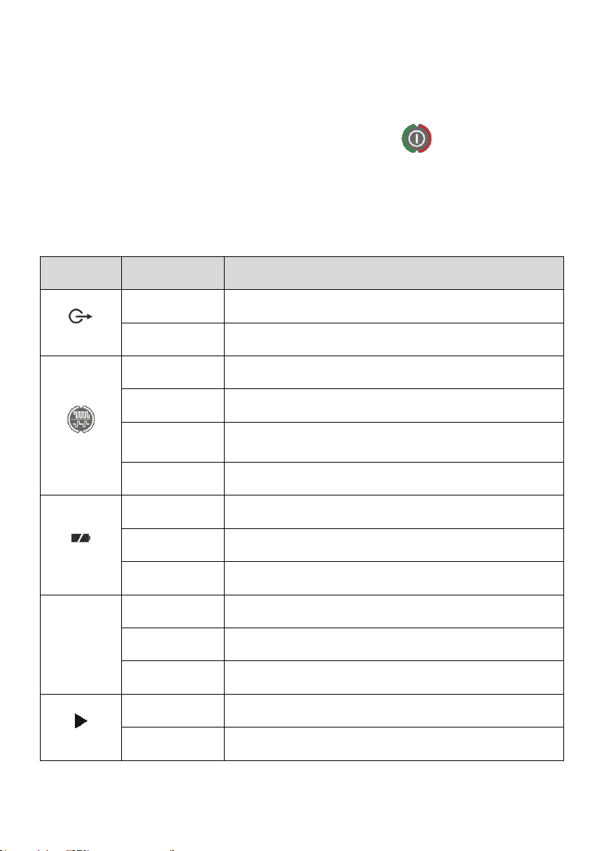
3.4.1 Signaling of the status and modes of operation of the transmitter
Tab. 2 Status and operation mode light indication
Indicator posi-
tion in Fig. 2
Indicator status
Transmitter status and operation mode
p. 8
Flashing light
The transmitter is adjusting to the load.
Continuous light
Transmitter stabilized the power output with the load.
P. 15
Continuous green
light
Continuous normal operation of the transmitter.
Flashing green light
Pulse normal operation of the transmitter.
Flashing red light
at a frequency of 1
Hz
Transmitter overheating. Signal is not generated. The generation is resumed
only when the transmitter is cooled down, but no sooner than in one minute
Continuous glowing
red
The “Output” sockets carry external voltage. The transmitter might have been
connected to live circuit.
p. 10
Constant glowing
Internal battery voltage in normal.
Flashing half of the
battery symbol
Internal accumulator voltage level ranges from 11.0 to 10.5 V which indicates
deep discharge of accumulator battery.
The battery symbol
flashes
The internal battery voltage is below 10.5 V. After 1 minute the transmitter will
be automatically switched off.
!
p. 9
No signal
Voltage of external power supply in normal range.
Continuous glowing
The voltage of the external power supply is between 11.0 V and 10.5 V. The
external battery is probably discharged.
Pulsing flashing
The voltage of the external power supply is below 10.5 V. After 1 minute the
transmitter will be automatically switched off.
p. 17
Moving from top to
bottom
Accumulator charges.
Constant lighting of
all three icons
Accumulator charged.
LKZ-1500-LITE ● LKZ-1500 –USER MANUAL
10
3.4.2 Direct connection –galvanic mode
3.4.2.1 Connecting the transmitter to the object
WARNING
Verify that the line to be tested is not at live voltage. Load connection to the trans-
mitter output is allowed only when the transmitter is switched off. The transmitter
direct connection to the examined live line is prohibited.
Socket shall be connected to ground pin driven into the ground at a distance of 5-10 m from the
route of the object. To increase the survey current, ground pin shall be earthed at a maximum depth.
Connect the blue wire to the output socket of the transmitter (Fig. 2 p. 14). The other end of the
cable, using a blue crocodile, should be fastened to a pre-grounded grounding probe. Use the red
wire to connect the output socket of the transmitter (Fig. 2 p. 13) to the conductive part of the object
(see Fig. 3).
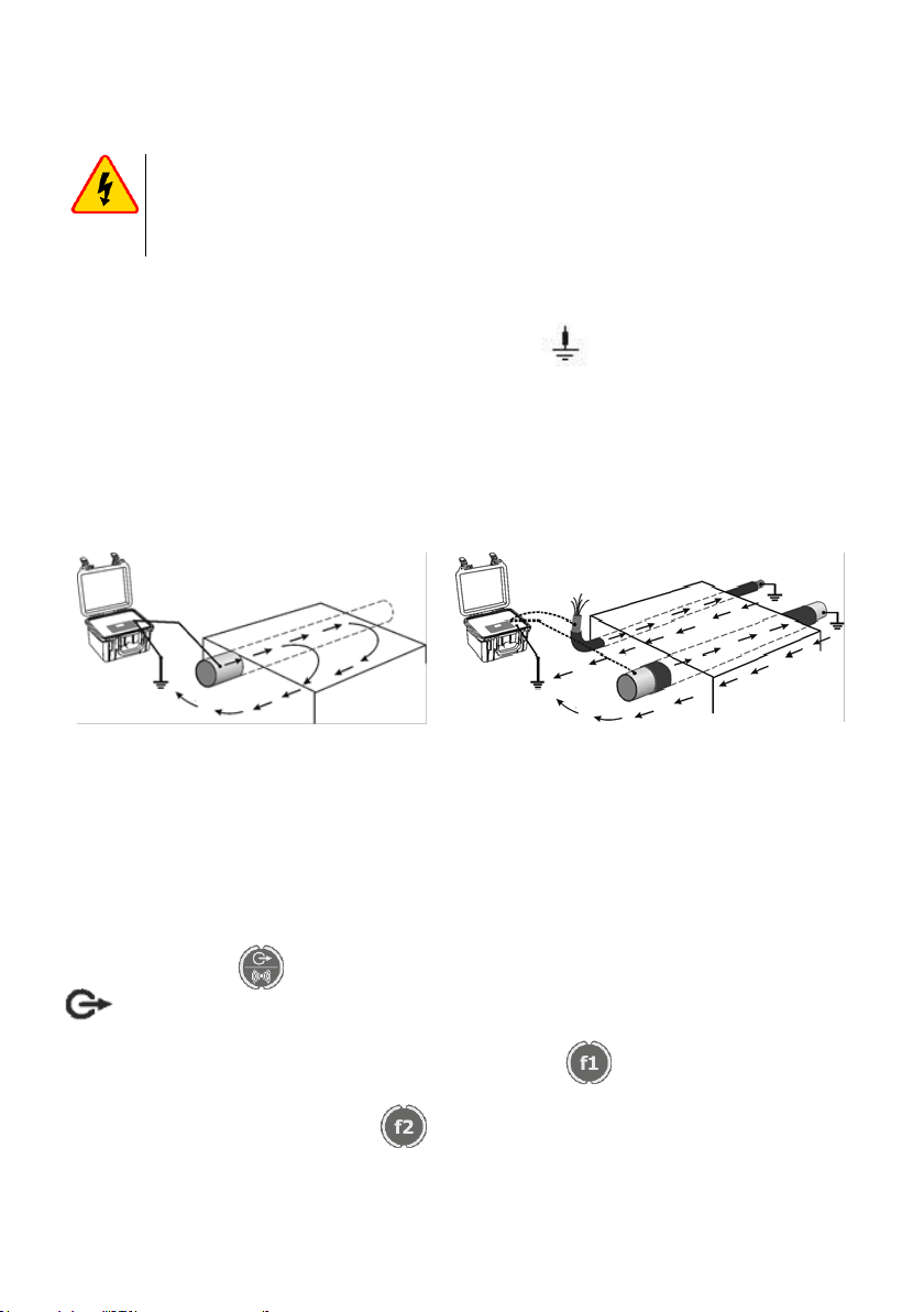
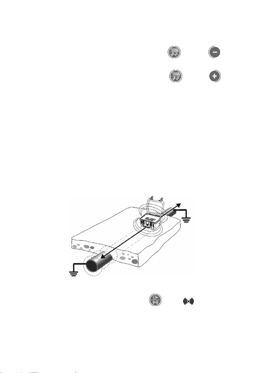
In the search for unearthed object, for example, gas pipeline or cable, it is preferable to earth the
object at far end (see Fig. 4) –it will provide maximum survey current. Otherwise, current will leak off
the ground through isolation capacitance and its level will decrease. As a result it will reduce possible
search range.
Fig. 3 Connection the transmitter to the
metal pipeline.
Fig. 4 Connection to cable armour (shield), to
one of the cords in case of unshielded cable or
to metal section of insulated pipeline
There are other methods of transmitter connection to objects or cables depending on the purpos-
es, for example, in case of insulation fault tracing. For more information see the section on Working
with A-frame.
3.4.2.2 Signal frequency selection
Turn on the transmitter and set the desired output frequency, power, and operating mode . In ad-
dition, with the button select the signal output from the transmitter's output sockets. The symbol
will appear on the display. Selection depends on particular search conditions and current task
and requires acquisition of practical skills by an operator.
Signal frequency selection is made by pressing the button and is frequency-loop : 273 →
1024 → 8928 → 33k → 273, etc. (see position 1 in Fig. 2).
Double frequency signal is made by the key with an indicator ↑↓ for double frequency 1024 [Hz]
and φfor double frequency 8928 [Hz].
LKZ-1500-LITE ● LKZ-1500 –USER MANUAL
11
Low signal frequency in the wet ground allows for maximum search range and minimum signal
routed to other communication lines or objects (273, 526 or 1024 [Hz]). But at low frequencies the
noise influence of power current and signals in adjacent lines is stronger.
High frequency (“8928”) in the dry ground allows for higher search range and lower power-supply
disturbance. Higher frequency “33k” is recommended when searching for insulated cables and lines
with far ends not connected to the ground. In this case, the survey current generated as a result of
ground leakage through distributed isolation capacitance is higher. In addition, high frequency is pref-
erable during wire-free connection of the transmitter to the objects or lines of communication (Fig. 5).
However, it should be borne in mind that at high frequencies there is a stronger penetration of the
signal from the transmitter to adjacent lines (objects), which may results in wrong search directions.
When the transmitter is operated in combination with LKO-1500 receiver, at high density of com-
munication lines, you can use current direction sensing function. The current flow from the transmitter
(direct current) or to the transmitter (let-through adjacent line return current). In this regard, set the
transmitter signal output at double frequency of 1024 [Hz] signaled ↑↓. Set operating frequency “1024”
for the receiver. Setting the output power of the signal.
3.4.2.3 Signal power output settings
You should correlate the settable power, desired search time, power supply source parameters
and estimated search range.
Increase or decrease power output by pressing the buttons . Indicator (pos. 5 Fig. 2)
shows power output value. Indicator on position 6 (pos. 6 Fig. 2) shows voltage output (V) and output
signal current value (А). Parameter can be selected by pressing the button .
If the desired current value cannot be obtained, check the grounding quality and / or change the
signal frequency for the ground type. If the transmitter cannot provide the specified power, it is auto-
matically limited to maximum possible value at the given load. In case of high load circuit resistance
when minimum power cannot be generated (for example, open load), power level indicator shows a
message: “-1”. Also power output limitation may be resulted from insufficient accumulator capacity.
Generally load conditioning time does not exceed one minute. If conditioning is longer, check
connections and ground quality, change power output or switch to continuous wave generation mode.
3.4.2.4 Transmitter operation mode selection
Continuous wave and pulsing generation modes are available for the transmitter. Continuous
wave generation mode is recommended when determining position of communication lines, its depth
and during insulation troubleshooting. Pulsing generation mode is recommended when searching for
communication line under high noise conditions or at low signal received, as it’s easier to determine
your own signal by typical pause in this mode. Also the transmitter power consumption is reduced.
Generation modes from continuous to pulsing are switched by pressing the button and dis-
played in time with output signal (the green diode is green) by indicator (pos. 12 Fig. 2).
LKZ-1500-LITE ● LKZ-1500 –USER MANUAL
12
3.4.2.5 Voltage output limitation
Mode of voltage output limitation to 30 V is activated for safety reasons during operations. For ex-
ample, it is reasonable to limit voltage output level during cable cord selection in case of body contact
with a cord.
To activate voltage output limitation, hold down the button and press (pos. 3 in
Fig. 2). On the display you will see indicator “V” flashing . In case the transmitter cannot provide pre-
set power, it is automatically limited to maximum possible value at the given load.
To deactivate voltage output limitation, hold down the button and press (pos. 4 in
Fig. 2).
3.4.3 Non-contact survey current generation in communication line
If the transmitter cannot be directly connected to communication line in galvanic mode, for exam-
ple, no access to conductive parts of communication lines or they carry voltage, the survey current
can be generated in the examined lines from induction coil or by inductive clamps.
3.4.3.1 Internal transmitter inductor
The transmitter with coil produces alternating magnetic field in the ground that generates current
in the line of communication. The higher is survey current, the lower is resistance of the closed circuit
being a part of communication line. Earthing of communication line ends is the best decision as
shown in Fig. 5. If there are no earth conductors, the survey current level is lower as its strength is de-
termined by capacitive current through line insulation. The current level is being higher with a rise in
frequency.
During operation in inductive mode transmitter shall be installed vertically along an axis of the ex-
amined communication line (Fig. 5).
Fig. 5 Induction current excitation in the localized object
For operation from internal inductor press the button . Symbol will be displayed. The
inductor reaches its maximum performance at 33 kHz.

LKZ-1500-LITE ● LKZ-1500 –USER MANUAL
13
It should be noted that:
the current level is substantially lower when it is generated in communication line by using
transmitter rather than direct galvanic connection;
transmitting signals are being routed to all adjacent current-conducting lines what may results
in wrong search directions;
the closer transmitter is located to communication line, the higher is the current level generat-
ed in communication line.
3.4.3.2 Inductive clamps
In case of access to communication line, for example, high voltage insulated live cable comes out,
it is reasonable to use inductive clamps. Due to better magnetic interaction with line circuit, they pro-
vide higher survey current generation and eliminate sending signal to adjacent communication lines.
Select the clamps to match the diameter of the clamped wire (see also section 13.2).
NOTE!
Do not connect conductive clamps to live bare conductors.
Current resistance shall be as low as possible in order to provide maximum current in the exam-
ined communication line circuit. It should be noted that the higher is operating frequency, the higher is
the level of the current generated in insulated and/or unearthed line when using clamps.
The clamps should be connected to the output sockets of the transmitter, while keeping the mark-
ings on the wires. The cable marked with the letter Ewith the grounding outlet of the transmitter
and the cable marked with the letter Hwith the load socket (p.13 Fig. 2). Grasp communication line
with clamp (Fig. 6). On the transmitter panel press the key to set the frequency from available.
Fig. 6 Induction of excitation voltage in localized object with transmitting clamp

LKZ-1500-LITE ● LKZ-1500 –USER MANUAL
14
4 LKO-1500-LITE / LKO-1500
The LKO-1500 Receiver paired with the LKN-1500 transmitter is designed to locate and trace ca-
ble and pipe lines (hereinafter referred to as the “utilities”). However, there is the possibility of self-
operation of the receiver, without aid of the transmitter, i.e.:
on the 50 Hz and 550 Hz frequencies it locates cable lines by detection induced signal of the
industrial frequency current;
on the 100 Hz and 300 Hz frequencies it locates utilities and finds areas of damaged insula-
tion of pipes by detecting Electrochemical protection signals;
on the 550 Hz and 1450 Hz frequencies it locates the areas of ground fault of overhead lines
by detection current harmonics;
in the SB (sound band) mode it locates utilities by re-radiated broadcasting and telephone
signals within the frequency band from 48 Hz to 14 kHz.
in the Radio modes it locates utilities by detecting induced broadcasting signals within the
frequency band from 10 kHz to 36 kHz.
4.1 Principles of operation
The Receiver locates utilities and cable faults by the induction method. Replacement sensors fa-
cilitate finding damaged insulation by the voltage caused by the current to the ground.
The alternating magnetic field induced by the utility and/or the voltage generated in the replace-
ment sensors are transformed into a signal form. This signal is amplified and processed by the digital
signal processor. Then the signal levels are displayed in a form of line bars and digital values in dB or
Volts. The indication may be supported with the audible signal.
4.2 Design and front panel of the receiver
Fig. 7 Design and identification of receiver sockets
3
1
2
4
5

LKZ-1500-LITE ● LKZ-1500 –USER MANUAL
15
No.
Description
1.
Power supply input, 12 V / 0.5 A (the centre pin is negative )
2.
Headphone jack –Jack 6.3 mm
3.
Battery compartment cover
4.
Outlet for extra equipment (A-frame)
5.
Speaker
A removable sun-protective cover can be installed by securing its two Velcro straps by the receiv-
er’s handle for easier operation in sunlight.
Fig. 8 Receiver with sun–protective cover
Fig. 9. LKO-1500-LITE receiver panel

LKZ-1500-LITE ● LKZ-1500 –USER MANUAL
16
Fig. 10.LKO-1500 receiver panel
LKZ-1500-LITE ● LKZ-1500 –USER MANUAL
17
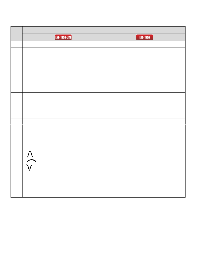
Tab. 3 Overview of the LKO-1500 transmitter control panel and display
Lp.
Functions description
1.
On/off button
On/off button
2.
Transmitter’s display
Menu button –enters / exits the menu
3.
Volume control button
Display
4.
Gain increase buttons
Button for saving displayed parameters and GPS co-
ordinates for further transmission to a PC;
5.
Gain set button for the specific signal strength
Button for increase of the signal, allows movement
through the Menu options
6.
Gain reduction buttons
Button for decrease of the signal, allows movement
through the Menu options
7.
Operating frequency selector button
Button sets optimum signal gain in the TRACE or
SENSOR channels (depending on actual control area).
Measures the utility depth and intensity of current.
Switches on/off the selected option in the Menu mode.
8.
Operating frequency
Button adjusts the sound volume
9.
Object depth / gain level (dB)
Button switches the available operating frequencies
10.
MODE button for selection of the locating mode: Sharp
Peak, Broad Peak, or Null
Button selects available locating modes. Switches the
control areas to change operating frequencies and
amplify signal between the TRACE and SENSOR
channels in the TRACE-SENSOR mode
11.
Enabled locating mode icons:
Sharp Peak
Broad Peak
Null
-
12.
Input signal strength bar graph
-
13.
Test object current
-
14.
Input signal limit violation icon
-
15.
Battery charge icon
-
LKZ-1500-LITE ● LKZ-1500 –USER MANUAL
18
4.3 Operating the receiver
Always observe safety rules when you work with live cables.
Do not apply voltage of more than 42 V to the open metal parts or jacks of the Receiver.
If the receiver is at a temperature different from the specified operating temperature, keep it at a work-
ing temperature –not less than 1 hour before use.
The instrument should be removed from the case and checked for proper covers, and mechanical
damage on the receiver and power supply casing.
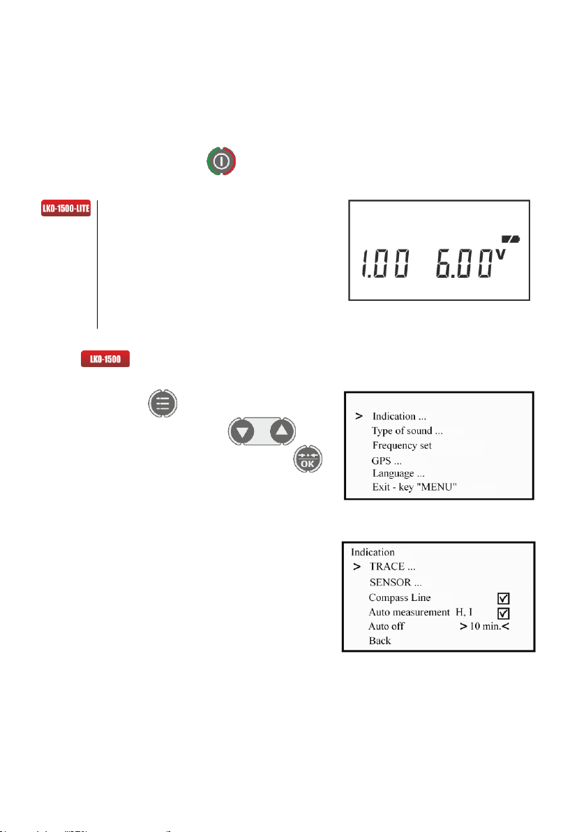
Turn off the device with the button. When powered on, the device turns on the firmware
version number and the supply voltage.
If the voltage is below 5.8 V, recharge
the battery or replace the disposable batter-
ies.
The supply voltage is indicated with the
battery icon while the device is on (Fig. 9,
item 15). When the battery is fully charged,
its charge icon is shown full. If the battery is
partially drained, one one half of its charge
icon is visible. If the supply voltage falls be-
low 5.8 V, the battery icon begins flashing.
4.4 Selection and setting the main parameters via Menu op-
tions
Press the button , to enter or exit the settings.
The menu is navigated with buttons . The
options may be selected and changed with the
button.
The Indication submenu lists the following options.
Fig. 11.Main menu
Fig. 12 Menu “Indication”
in LKO-1500
Other manuals for LKZ-1500
1
This manual suits for next models
2
Table of contents
Other Sonel Security Sensor manuals


