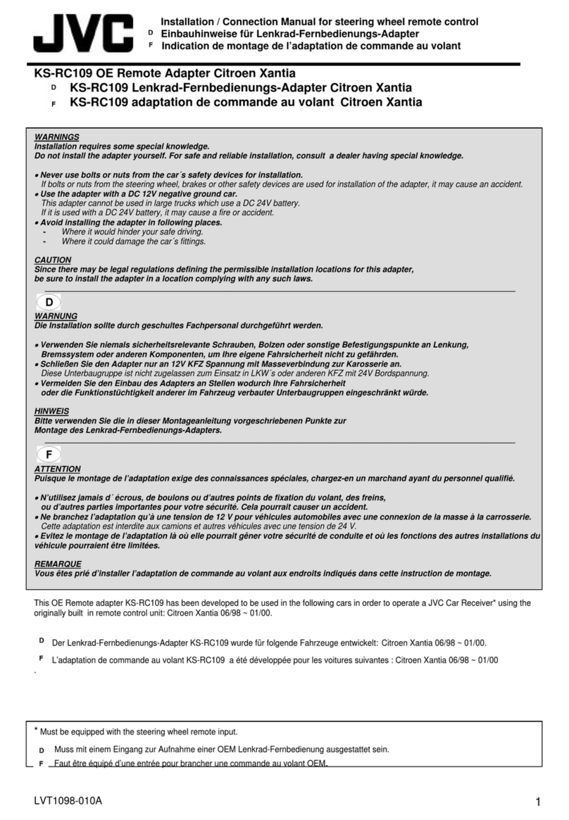
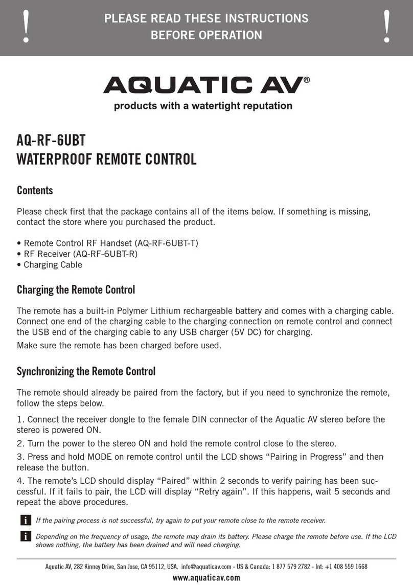
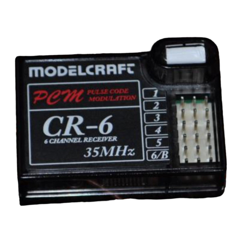
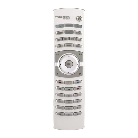
Sonelco P3670 Operating manual

USER AND INSTALLATION
MANUAL
KIT P8106
SYSTEM COMPONENTS
- P3670 ELECTRONIC MODULE
- P4803 REMOTE CONTROL
- LOUDSPEAKERS
- ACCESSORIES

SYSTEM COMPONENTS
P8106 KIT COMPONENTS:
A: 1- P 6370 ELECTRONIC MODULE
B: 2 - PT112-01 LOUDSPEAKERS
C: 1 P4803 REMOTE CONTROL
D: 6METRES OF PARALLEL CABLE
FOR LOUDSPEAKERS
1METRE OF ANTENNA CABLE
OPTIONAL:
E: P9302 AUXILIARY CONNECTOR
A. P3670 ELECTRONIC MODEL
B. LOUDSPEAKERS
C. REMOTE CONTROL
D. ACCESSORIES
2
A
B
CD
E
For extension of functions:
- remote switching on
- second stereo channel
- emission of general and area calls

3
A. ELECTRONIC MODEL - GENERAL FEATURES
1.5 w + 1.5w / 8 Ohm power
230 V / 10VA power supply included
FM stereo tuner
Auto SCAN (automatic search and memorising of up
to 30 radio stations)
Auto ON (it switches on automatically when connected
to the power supply). Useful if connected to the roof
lights. Selectable by means of switches.
Digital regulation of volume, Bass and treble.
7 quick access memories
SuperBass function
'Ideal' sound
Installation by means of a hole made in the roof for the
loudspeaker, without needing another hole for the IR.
The P3670 electronic module is provided separately or included in the P8106 KIT
Capturer for external IR and cabling
Switching Mono/Stereo on the module itself or from the remote control.
Entry to REMOTE, to which a light presence detector can be connected (external and not included) for the auto-
matic activation of the module

4
B - LOUDSPEAKERS
P7112 loudspeakers, 2" and 8 Ohm.
Delivered separately or included in P8106 KIT With module P3670, any other type of loudspeakers
can be used, or loudspeakers of the Prestige Line,
with 8 Ohm impedance
The connection of up to 4 loudspeakers of 16 Ohm
impedance is possible, covering a maximum area of
80 m2 at a height of 2.5 m
NOTE: For more information, please refer to Prestige Line
catalogue.
P7375
P7350
P4739
P4715 - P7141- P4716 P4713
P4712
P7125
P4734
P4736
OTHER LOUDSPEAKERS
Other loudspeakers

5
C - REMOTE CONTROL - QUICK REFERENCE GUIDE
1. ON-OFF - Switches the receiver operation on and off.
2. LED - Indicates operation, flashes when pressing any key.
3. AUX/TUN - To select between the internal tuner and the external
music channel (optional)
4. STORE - Used for the manual memorising of the radio station that
is being listened to in one of the 7 direct access memories.
5. SCAN - Used to make the tuner search for the next radio station.
6. KEYS - Allow direct access to the first 7 tuner memories.
7. IDEAL - Return to the pre-defined default values for Volume, Bass
and Treble.
8. DEL - deletes the current memory.
9. SB - Connection or disconnection of the SUPERBASS, bass rein
forcement.
10. PR - /PR+ - Change of the previous memory (PR-) to the following
(PR+)
11. VOL - /VOL+ - To increase or decrease the audio volume.
12. BASS - /BASS + - To increase or decrease the bass level.
13. TREB - /TREB + - To increase or decrease the treble level.
34152
6
68
79
13
10
12
11
The selected values of Audio Channel, Volume, Bass, Treble, Notice reception Volume, Superbass status, active
memory or selected frequency are memorised when going on Stand-by and are saved in the event of switching off
of the receiver, being recovered when switched on again.

6
C - REMOTE CONTROL - FUNCTIONS
START
Press key 1 (ON/OFF) pointing the remote control to the infrared receiver, located next to any of the two loudspea-
kers. Connection: press key 1 (ON-OFF), and the receiver led will be lit up. Led lit up - normal functioning
Disconnection: press key 1 (ON-OFF), and the receiver will be switched off, remaining in STAND-By
mode, memorising the last radio station tuned and saving the values corresponding to volume, bass and treble.
AUTOMATIC MEMORISATION OF RADIO STATIONS - AUTOSEARCH
In order to carry out this memorising process, the receiver should be in the STAND-BY mode, with the led
off.
By maintaining key 4 (STORE) pressed for three seconds, the AUTOSEARCH begins, in which the receiver con-
nects, the led lighting up, and starts searching for all the radio stations in order, from the beginning to the end of the
band, sequentially memorising them in the tuner memories, starting with number 1 to a maximum of 30.
Once the process is over, the receiver beeps twice and switches off. Every time the AUTOSEARCH process is
carried out, the previously memorised frequencies are deleted and replaced by the new ones.
MANUAL MEMORISATION OF RADIO STATIONS
Press key 4 (STORE) and then the desired quick memory key 6(from 1to 7). The correct memorisation is indica-
ted by beeping three times. If you wish to cancel the operation, before pressing the quick memory key, simply press
the STORE key again. Once the radio stations have been selected, by simply pressing any of the keys 6, numbe-
red from 1to 7, the memorised radio station will be heard. Apart from memorising up to 7 direct dialling radio sta-
tions, more radio stations can be memorised, up to a maximum of 30, by pressing key 4 (STORE) and then key 10
(PR+), memorising the selected frequency in the first free memory slot existing. If there are no free memory slots
because the maximum number has been reached, this is indicated by emitting a longer deeper beep.

7
C - REMOTE CONTROL - FUNCTIONS
SEARCH FOR RADIO STATIONS
Press key 5 (SCAN) and the tuner will search for the following radio station. Its pressing is indicated with a beep
and a flashing of led 2 and of the infrared receiver led.
The receiver remains in silence until it finds the following radio station.
When the scan search reaches the end of the 108.00 MHz band, it returns to the beginning of the 87.50 KHz band,
beeping deeper.
SEARCH FOR MEMORISED RADIO STATIONS
These can be obtained in two ways, one, by pressing any of the keys 6numbered from 1to 7, allowing direct access
to the first 7 radio station memories. Its pressing is indicated by a beep and a flashing of the led.
The other way is obtained by pressing the keys 10 (PR -/PR+) changing to the previous memory (PR -) or to the
following (PR+) between all the radio station memories, up to a maximum of 30.
When reaching the last one, the first one will follow, if pressing (PR+). When reaching the first one, the last one will
follow if pressing (PR -).
DELETION OF RADIO STATIONS
To delete the current memory, if the radio station is not of our interest, or if it is just a noise, press key 8 (DEL), main-
taining it pressed for two or three seconds, the tuner indicates the deletion by a beep and a flashing of the led.
When the radio station is deleted, the memory slot will be free for another memorisation, directly listening to the follo-
wing memorised radio station.

8
C - REMOTE CONTROL - FUNCTIONS
PREDEFINED VALUES
The P8106 kit leaves the factory with predefined values for Volume, Bass and Treble, that can be modified by means
of the activation of the volume keys 11 (VOL- VOL+), the bass level, keys 12 (BASS- BASS+) or the level of treble,
keys 13 (TREB- TREB+). Its action is indicated by the flashing of the receiver led that, upon reaching the limits (mini-
mum and maximum values) stops flashing.
To recover the pre-defined factory values, press key 7 (IDEAL), automatically adjusting the three values, indicated
by a beep and a flashing of the receiver led.
SUPERBASS FUNCTION
To connect or disconnect the SUPERBASS function, reinforcement of bass, press key 9 (SB).
The connection is indicated by a beep and a flashing of the receiver led.
The disconnection is indicated by two beeps and a flashing of the receiver led.
QUICK OPERATION GUIDE:
Once the kit is installed, with the receiver in the STAND-BY mode, with the led off, keep key 4 (STORE) pres-
sed for three seconds, for the AUTOSEARCH to start (see page 6).
Then start the normal functioning, pressing key 1 (ON / OFF) then being able to select any radio station, as
with the automatic search up to 30 radio stations are sequentially stored.
For the selection of deletion of radio stations stored during the autosearch, use the corresponding functions
indicated in this manual.

9
C - REMOTE CONTROL - CONFIGURATION PARAMETERS
The configuration parameters should only be carried out with the receiver in the STAND-BY mode, using the keys 6, numbered from
1 to 6.
Key numbered 1 - By keeping it pressed for three seconds, the RF sensibility used for the search of radio stations in 15uV (maximum
sensibility) is selected. This is indicated by means of a flashing of the led and a beep.
This configuration is recommended when the module is installed in an area with bad radiofrequency reception.
In this way we make sure that the tuner receives the maximum number of radio stations as possible.
Key numbered 2 - By keeping it pressed for three seconds the RF sensibility used for the search of radio stations in 35uV (value pre-
defined in the factory). This is indicated by means of a flashing of the led and two beeps.
Key numbered 3 - By keeping it pressed for three seconds the RF sensibility used for the search of radio stations in 75uV. This is indi-
cated by means of a flashing of the led and three beeps.
Key numbered 4 - By keeping it pressed for three seconds the RF sensibility used for the search of radio stations in 300uV (minimum
sensibility, it will only receive local radio stations). This is indicated by means of a flashing of the led and four beeps.
Key numbered 5 - By keeping it pressed for three seconds the status of the receiver changes from Mono to Stereo. The default value
is stereo.
The mono mode is indicated by a flashing of the led and a beep, whilst the stereo mode is indicated by a flashing of the led and two
beeps.
Key numbered 6 - By keeping it pressed for three seconds the tuner frequency starts at the beginning of the FM frequency (87.50
MHz). This is indicated by a deep beep

10
ASSEMBLY
CONNECTION TERMINAL STRIPS
1 2 3 4 5
7 6 8
1 - IR: remote control receiver connector
2 - ANT: aerial signal
3 - GND: aerial earth
4 - loudspeaker connection
5 - loudspeaker connection
The P3670 electronic module can be connected to the 230
V electricity supply network, with the following alternatives:
SUPPLY AT 230V
IMPORTANT: Make sure of a
correct connection before
starting the installation.
6 - SwitchtoselecttheSTEREOorMONOconfigu-
ration.
7 - AUTO ON switch to configure the initial start-up
mode
ACTIVATED: starts in ON
DEACTIVATED: starts in OFF
8 - prepared for the inclusion of the P9302 auxiliary
connector
Rip the trap open for connection (see page 14).
Directly to the electricity installation from any point
(junction box, sockets, etc.)
Connected, in parallel, from a light point.
In this case the electronic module will be operated
by the same switch that controls the light point.
The AUTO ON switch should be connected

11
ASSEMBLY
A. Make two 60 mm diameter holes in the surface where the P8106 kit is
to be installed, for the location of the P7112 loudspeakers. We recom-
mend the installation to be carried out in a visible area, without any obs-
tacles, for the correct reception of the infrared rays of the remote contro-
ller.
A
BB. We recommend the installation of
a loudspeaker, taking the cables to
the opposite hole as well as the 230
V electric supply cables.
Once the connection to the loudspe-
aker has been checked, fix this to the
corresponding surface or ceiling.

12
ASSEMBLY
C
The loudspeakers are connected to the P3670 electronic module in their corresponding strips, as well as the 230V electri-
city supply cables and the aerial connection.
Once all the connections have been checked, insert the P3670 electronic module through the hole, place it on the false roof
and then put the loudspeaker in place.
The infrared receiver is fixed on the edge of the loudspeaker, or next to it.
"Extend the
antenna cable
correctly"

13
ASSEMBLY
D
Point the remote control at the loudspeakers, following
the instructions included in this manual
The infrared receiver is fixed on the edge of the
loudspeaker, or next to it.

14
E - AUXILIARY CONNECTOR - OPTIONAL
The electronic module P3670 has an auxiliary connexion base
for the carrying out of other functions. The P9302 auxiliary con-
nector is inserted in this base, supplied with a flat cable and a
terminal strip with various connexion terminals. These terminals
are as follow:
REM - Remote switch. Its bridge with terminal 4 switches on the
receiver, in exactly the same way as pressing the ON/OFF but-
ton on the remote control.
2 - Supply outlet +15V/50mA (as a maximum to supply an input
module)
4 - Audio earth and supply negative.
5 - Input left audio external external channel (1.5V RMS sensitivity) (Connect with the AUX/TUN key)
6 - Input right audio external external channel (1.5V RMS sensitivity) (Connect with the AUX/TUN key)
7 - Audio warning input (1.5V RMS sensitivity)
8 - Area reception warning input switch (+15V = Active)
9 - General reception warning input switch (+15V = Active)
The reception of warnings (external transmitter) occurs automatically and separately from the state of the receiver (if it is ON or
OFF, inTUN or inAUX). The reception volume of warnings is separate from the volume of the music, and can be adjusted during
reception of the warning by pressing key 11 (VOL-VOL+), that stores separately from the volume of the music
To toggle between the internal tuner and the external channel, press key 3 (AUX/TUN). The switching on of the tuner is indi-
cated by a beep whilst that of the external channel is indicated by two beeps. The external music channel is obtained from
an input module PC3110 or from any Prestige Line series model
Break open to
connect

E - AUXILIARY CONNECTOR - OPTIONAL
With the P9302 auxiliary connector the following options can be accessed
REMOTE SWITCH ON
Possible combination with remote switching on or off of lights and other systems with proximity sen-
sors or similar.
SECOND CHANNEL
The P3670 electronic module has an input for a second stereo channel by means of an input module
PC3110, which can be connected to any source of sound.
The PC3110 module is connected to the installation by means of terminals 2 and 4 (supply input), and
terminals 5 and 6 (audio output).
TRANSMISSION / RECEPTION OF WARNINGS, GENERAL CALL, OR BY AREA
A call PC1350 transmitter module can be installed. This is connected to the installation by means of
terminals 2 and 4 (supply input), and terminals 7, 8 and 9 (warnings and calls).
A desk can also be used for P5552, P5556, or P5580 warnings. In this case a supplementary supply
P3230 or another Prestige Line source of supply must be used.
NOTE
-
Installation extension: The "Easy Series" modules can be used to extend the con-
ventional Prestige Line installations, with an easy and quick assembly
*The supply power of the connector terminals 2 and 4 is designed for the installation of only
one of the models described previously
15

SONIDO, ELECTRONICA Y COMUNICACIONES, S.A.
HEADQUARTERS:
C/.Africa, 1 - 3 bajos - Tel. 976 259 125 - Fax 976 373 775 - 50007 ZARAGOZA - Spain
www.sonelco.com
Sonido, Electronica y Comunicaciones, S.A., reserves the right to carry out modifications without prior notice. Sonido, Electronica y Comunicaciones, S.A., accepts no
responsibility for any errors or omissions in this manual
This manual suits for next models
1
Table of contents
