Sonic KCS-3500 User manual

Model KCS-3500
Color Scanning Sonar
Operation Manual
Ver.1.6
5


i
Warning
!
Danger
!
! Caution
Safety and handling instructions
· In order to use the instrument safely and correctly, fully read and understand this
operation manual.
· Ask our repair service personnel about maintenance of the instrument. Be sure not to
have the instrument overhauled by a anyone other than qualified repair personnel.
· Always keep this manual handy.
・Pictorial Indication
In order to correctly use the product and prevent injury to users or other persons or damage
to property from occurring, be sure to carry out the following matters according to the
indication of this manual and product. The indication symbols mean the following:
This symbol means “if you mishandle the instrument, occurrence of
imminent danger causing death or a serious injury is anticipated.
This symbol means “if you mishandle the instrument, the possibility of
causing death or a serious injury is anticipated.
The symbol means “if you mishandle the instrument, the possibility of
causing a moderate or light injury, or damage to property, is anticipated.
Danger
Prevention of electric shock by high voltage part
1.
When you check the internal portion for maintenance or inspection, be sure to turn
the power switch off because high voltage is used in some parts.
2. At the inspection, wash away salt on your han
ds, or when work clothes, shoes, or
the like is wet, change it with dried one.
3.
In the unlikely event that you find a person struck by electricity, if you directly touch
the person, you may be also in danger of receiving an electric shock. Therefore,
infor
m everybody of it without panic in a loud voice and turn the power switch off,
or get the person off the spot using a plate or the like. Then bring the person back
to life by artificial respiration or general method.
!

ii
Warning
Warning at the check of the ship bottom part or the instrument .
1
. When you perform the checking at the ship bottom part, be sure to wear a helmet
and safety shoes, act in pairs and create a system so as to communicate with each
other at any time.
!
Caution
Caution about installation location.
1. Avoid using the instrument at a location where the temperature becomes 50℃
or
more, such as a location where the instrument receives direct sunlight for a long
time or a location in the vicinity of a heating appliance.
2. Avoid using the instrument at a location where the i
nstrument directly receives
spindrift or at a humid location.
!

iii
Safety of the hoist unit
・Ship speed resistance
When using the hoisting device, be sure not to exceed the following ship speed resistance of
the hoisting device. When used in excess of the ship speed resistance, the hoisting device
may be damaged and cause an accident.
Ascent 15 knots or less
Hoisting
operation
Descent 15 knots or
less
ship speed
resistance
16 knots
・Change electrolytic corrosion-preventing zinc plates annually.
Be sure to perform electrolytic corrosion prevention. If electrolytic corrosion prevention is
not performed, the transducer may fall accidentally or there may be an influx of seawater into
a dome, in the worst case.
For the transducer
The transducer of this sonar system is filled with castor oil inside. This castor oil may steep
from the transducer cable due to outside temperature change, but it does not affect the
performance.
For preventing damage at sea
When the transducer or the hoisting device is damaged at sea, the sonar system can not be
used, accordingly, the operation or safe navigation is sometimes hindered. Furthermore, it
takes a large amount of time and cost to exchange and repair the transducer or the hoisting
device.
In order to prevent these accidents from occurring, store the transducer by performing the
following operations when conditions are as described below.
1.Condition
1) Sea condition with many float and drift
2) The case of getting out of an encircling net by a lightship of round haul netter fleet
3) A shallow place where ropes or wires are set up under seas
4) During an anchorage of a ship

iv
2. Transducer storage operation
- Press the “ascend” key of the hoisting device on the operating portion and store the
transducer.
- During ascending, an arrowhead “” is indicated in upper right of the screen and the
display bar of the hoisting amount is gradually reduced.
- When the transducer is stored and the hoisting device goes up to the upper limit, the
upper limit message is displayed and the hoisting device stops.
・On the battery·electric cell exchange
In this instrument, a battery is used to have clock function. Perform exchange of a battery
periodically.
Be sure to change any expired batteries. If you leave a battery unchanged, there is a risk of
smoking and ignition.
<Target of exchange>
As to a battery, the target life is set to about two years as a standard. When the battery is
used under a high temperature, the life becomes shorter.
<Exchange method>
As to the exchange of a battery, make contact with our service personnel.
Batteries are valuable and recyclable resources. In changing batteries and used
product disposal, cooperate in recycling.
Fan Motor Replacement
This system is designed to prevent internal temperature increase in the processor, receiver
and transmitter by installing fan motors in them. If those fan motors are not working, an
increase in the internal temperature of those devices may cause their malfunction. The
outlets of the fans, therefore, should be inspected regularly to check that the fan motors are
working properly.
Although the service life of the fan motors in general is 50,000 hours, it varies depending on
the use environment. For this reason, fan motors must be replaced periodically.
<How to Replace>
For replacement of the motor fans, please contact our service engineers.

v
For the safety operation! How to use the emergency stop
If a problem occurs, execute the emergency stop. Even if the hoist unit is ascending, power
supply is shut off by executing the emergency stop. To execute the emergency stop, press
both keys of and at the same time.
Caution
· When executing the emergency stop, the whole system power supply is shut off. Take care
not to press these keys together, during normal operations.
Press both keys of and
at a
same time.
Emergency Stop

vi
INTRODUCTION
Thank you very much for purchasing our color scanning sonar. We have designed and manufactured
instruments under strict quality controls for performance and quality, and have accordingly won high levels
of satisfaction and confidence from our customers.
Since the KCS-3500 has the following features, please read this instruction manual carefully and make
good use of the fine performance of this instrument.
・Features
· The entire circumference can be searched at the same time.
· Medium frequency and high resolution. Valuable fish species can be identified.
·High-resolution display because display pixel number is SXGA (1280×1024)
· Fish school density is understandable by using the 32 colors display.
· Space saving by LCD display
· With excellent operability, this system can store up to 10 set values depending on the fishing ground.

1-1
Chapter 1. Outline of basic operation
1.1.Emergency stop
In case of occurrence of an abnormal situation such as “power supply is not cut off”,“Keys
to the operating portion do not function”, or “Sonar action has stopped” even though you
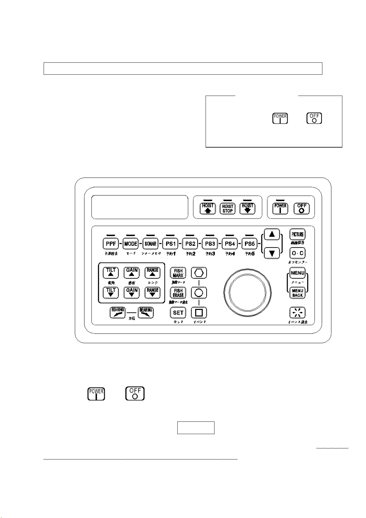
press key, press both keys of “power on key” and “power off key” at the
same time, so as to cut the power supply of the whole system.
When the power supply is cut off by the emergency stop, the hoist unit remains in the
state before cutting off the power supply. If it remains untouched, there is a danger that a
transducer will be damaged. Therefore, apply the power supply again and activate the
hoist unit to store the transducer for prevention of danger.
However, when the power supply cannot be applied again, store the transducer by manual
operation of the hoist unit. Refer to chapter 7 “Operation and Maintenance of Hoist unit
“ as to how to perform manual operation.
1.2. Basic operation
1.2.1. On/Off of power supply
(1) Apply the power supply
Push the power key at the operating portion.
It takes about 2 to 3 minutes for the startup of a sonar screen. The sonar is started up
by the mode which was used before cutting the power supply.
(2) Cut the power supply
(a) Push key of the hoist unit to store the transducer.
During the ascent of the transducer, the length of the hoisting amount display bar
located in upper right of the screen is reduced. Further, during the hoisting operation,
the arrowhead “” is indicated on the left of the hoisting amount display. When the
operation is performed up to the upper limit, the hoisting amount is indicated as
completely empty. Further, a message of the upper limit is indicated on the screen.
Perform the ascent operation of the hoist unit at a ship speed of 15 knots or less.
When the hoisting amount decreases to 40% or less, transmission is automatically
stopped by the operation of “AUTO TX” (effective at the time of setting AUTO TX to
“ON”).

1-2
(b) Push the power switch to cut the power supply.
(Note)
If you cut the power switch without storing the transducer, the storage operation of the
transducer is automatically performed by the “Automatic ascending operation”. After
storing the transducer up to the upper limit, the power supply is automatically shut off.
In addition, when cutting the power supply for safety, cut the power supply after storing
the transducer.

1-3
1.2.2.Descent and ascent of transducer
(1) Project transducer
Press the key of the hoist unit to lower the transducer. During the
descent of the transducer, the hoisting amount display bar located in
upper right of the screen is filled in proportion to the hoisting amount
and the upper lamp of the descending key flashes on and off.
Further, during the hoisting operation, “¯” is indicated on the left of the
hoisting amount display. When the operation is performed up to the
lower limit, the hoisting amount display bar is completely filled in and
the upper lamp of the descending key flashes on. The message for the lower limit is
indicated on the screen. Perform the descent operation for the hoist unit at a ship speed
of 15 knots or less.
When the hoisting amount increases to 40 % or more, transmission is automatically
started by the “AUTO TX” operation (effective at the time of setting AUTO TX to “ON”).
(2) Store the transducer
Press the key of the hoist unit to store the transducer.
During the ascent of transducer, the length of the hoisting amount display bar located in
upper right of the screen is reduced and the upper lamp of the ascending key
flashes on and off. Further, during the hoisting operation, the arrowhead “” is indicated
on the left of the hoisting amount display.
When the operation is performed up to the upper limit, the hoisting amount is indicated as
completely empty and the upper lamp of the ascending key flashes on. Further, a
message of the upper limit is indicated on the screen.
Perform the ascending operation of the hoist unit at a ship speed of 15 knots or less.
When the hoisting amount decreases to 40% or less, transmission is automatically
stopped by the operation of “AUTO TX”. (Effective at the time of setting AUTO TX to
“ON”)
(3) Stop of transducer ascent and descent operations
When you want to stop the hoist unit operation during ascent or descent operations,
press the key. The upper lamp of the key is lit.
The hoisting amount at the time of stopping the hoisting device is indicated. When you
want to perform the ascent or descent operation again, press or key.
↓

1-4
1.2.3.Display screen
Regarding the layout screen image mode and sub display of sonar, there are 5 types of
displays. By performing the switching and the display as the need arises, they can be used
more effectively.
· “SONAR AREA”: Layout screen image mode
1. “FULL SCREEN” All screen sonar display
2. “HORIZONTAL” Horizontal sonar display
3. “MULTI” Multiple image display
4. “F/F” Fish finder display
5. “AUDIO” Audio display
1.2.4.Sensitivity adjustment
Receiving sensitivity is adjusted by the GAIN keys and in the operating portion.
The sensitivity can be set in the range of 0.0 to 10.0. The sensitivity is raised by the
key or lowered by the key. The sensitivity is adjusted such that the fish shoal echo
clearly appears on the screen and the noise is minimized. In addition, this instrument
executes the sensitivity control of TVG and if the distance is increased, the sensitivity is
automatically increased. By doing so, fish schools at both long and short distances are
displayed similarly on the screen.
1.2.5.Depression angle adjustment
The depression angle is adjusted by the depression angle keys and in the
operating portion. The depression angle can be set by 1° (degree) in the range of from +3°
(upward direction from the horizontal direction) to -60° (downward direction from the
horizontal direction).
The depression angle is adjusted to upward direction by the key or adjusted to
downward direction by the key. It is adjusted to the direction where you want to search
fish schools.
As for the depression angle operation, there are 4 modes: manual, auto, one and track.
1.2.6. Range adjustment
The range can be adjusted with the range keys and keys of the operation
section.
A depression angle can be set to a long distance with the range key , and to a short
distance with the range key . These keys can be used to adjust the fish school
detection range.

2-1
Chapter 2. Names and Function of the operation keys
2.1.Name of the keys
2.2.Key Functions
1. Power On Key : The whole system power supply is ON.
2. Power Off Key : The whole system power supply is OFF.
* Emergency stop key : In the event of an emergency requiring instantaneous
cutting of the power supply, the whole system power
supply is cut by
pushing both key and key at the same time.
7. Sensitivity ▲▼key
11.Event erasing key
13.Menu back key
2.Power off key
3.Ascent key
4.Hoist stop key
5.Descent key
19.Two-
touch keys
block
6.TIlte▲▼key
8.Range▲▼key
18.Setting key
10.Event key
12.Menu key
20.Track ball
14.Picture save key
15.Off center key
17.Fish school mark erasing key
9.Bearing mark
16.Fish school mark
1. Power on key

2-2
3. Ascent key : The transducer is stored.
4. Hoist stop key : The hoisting operation of the transducer is stopped.
5. Descent key : The transducer is projected.
6. Tilt keys : Transmission and reception beam angle are changed
to the water surface direction by the key, or
changed to the sea-bottom direction by the
key.
7. Gain keys : The receiving gain is increased by the key, or
decreased by the key.
8. Range keys : The display range is changed to longer range by the
key, or changed to shorter range by the key.
*The adjustment of Tilt, Range and Sensitivity is valid for the display with a cursor.
9. Bearing mark keys : An acoustic sound mark / vertical image direction
mark is moved clockwise by key or
counterclockwise by key.
10. Event keys : An event mark is indicated in the cross cursor position
(three types, the maximum 10 for each mark).
is also used when selecting a menu.
11. Event erasing key : Older event marks are erased in the order of hexagon,
round and square. Also, it is possible to erase any
event mark in the cross cursor position.
12. Menu key : The menu indication is switched to ON.
13. Menu back key : The menu indication is switched to OFF.
14. Picture save key : This key is not for use.
15. Off center key : Sonar image display range is indicated with enlarged
by 1.5 times. It switches from ON to OFF. When
displaying a cross-section screen, the depth of
cross-section screen is enlarged by pressing
with the cross cursor in the cross-sectional area.
16. Fish school mark key : Fish school mark of Estimated fish school position is
displayed.
17. Fish school mark erasing key : Erase of the fish school mark.
18. Setting key : A load point · timing of enlarged image / multi image,
casting net, or the like is set.

2-3
19. Two Touch Key Block : The keys in this block can be used in combination
with the and keys. Select a function key
first (then the light of the key turns ON), and change
its set value with the and keys.
a. PP Filter Key : This key is used when there is sea noise or interference
from other boats. The modes can change in the order
from “SOFT” → “MEDIUM 1” → “MEDIUM 2 ” → “HARD
1” →“HARD 2 ” →“SOFT”. The interference removal
level is most powerful in “HARD 2”. However, an
interference removal level that is too strong results in
bad smoothing of the image. Normally, the mode should
be set to “SOFT”.
b. Mode Key : This key is used to change the screen.
c. Sonar Memory Key : This key is used to restore the memory selected from
among the internal card STD from 1 to 10.
d. Preset Keys - : Each key is used to register one menu item selected
from the preset menu.
e. UP Key : This key is used to increase a set value.
f. DOWN Key : This key is used to decrease a set value.
20. Track Ball : It is used to move the cross cursor.
a. PP Filter Key b. Mode Key
c. Sonar Memory Key d. Preset Key
e. UP Key
f. DOWN Key


3-1
Chapter 3. Marks and Numerical Displays
The following marks and numerical values can be input.
1.Cursor information: Displays data information of Latitude & Longitude of
cross cursor. Displays direct distance, horizontal
distance, depth and compass bearing from own boat
position to cross cursor.
When you do not input data of latitude and longitude
of own boat, these data of cross cursor is not shown.
(*)
* Remarks: There would be the equipment that you cannot connect with
KCS3500. Please contact our service engineer before connecting.
(Multiple distance marker)
2.Bearing mark
3Audio marker
4.Bowl ine 8.Range
7.Tilt
6.Gain
5. Int. memory numbers
9.Stroke
10.Date&Time
11.Latitude & Longitude
12.Ship speed
13.Heading
14.Course
15.Depth
16.Water temp
17. Wind speed&Wind direction
18.Event information
20.Own ship mark
19.Cross cursor
21.Wake mark
24.Event mark
23.Event mark
22.Event mark
26.Color bar
25.Range marker
1.Cursor information
28. Fish school mark
29. Moving direction of fish school
27 External Synchronization

3-2
2.Bearing mark: Indicates the bearing scale. It changes after inputting
bow-bearing information from external equipment. (*)
3.Audio mark: This mark shows the range of audible sound, that is
a signal generated in the region between the
two lines can be detected.
4.Bow line: This line shows a direction in which the ship
goes.
5.Internal memory number: This field shows a memory number from which
number, settings being currently used are
loaded.
6.Gain: This field shows gain specified.
7.Tilt: This field shows the angle of depression of a
directional transmission /reception beam.
8.Range: This field shows the range of the sonar
horizontal image.
The range depending on an off-center value.
9.Stroke: This field indicates the elevation of a hoist.
10.Date & time: This is the current date and time.
11.Latitude&Longitude: It shows latitude and longitude of own ship.
The input from external equipment is
necessary. (*)
12.Speed: It shows own ship speed information. The
input from external equipment is necessary. (*)
13.Heading: It shows heading information. The input from
external equipment is necessary. (*)
* Remarks : Please contact our service engineer before connecting with an
external equipment.

3-3
14.Course: It shows course of own ship. The input from
external equipment is necessary. (*)
15.Depth: It shows water depth information. The input
from external equipment is necessary. (*)
16.Water temp.: It shows water temperature .The input from
external equipment is necessary. (*)
17.Wind speed & wind direction:
It shows wind speed & wind direction. The input
from external equipment is necessary. (*)
18.Event information: It shows event mark.
You can select even information from
relative/deviation/latitude& longitude.
“Relative” shows horizontal distance, depth and
compass angle.
“Deviation” shows deviation distance and deviation
speed.
“Latitude & longitude” shows these of event mark, but
input from external equipment is necessary. (*)
19.Cross cursor: With a track ball of operation part, you can move
freely.
20.Own boat mark: This mark indicates the position of the ship. It
appears in the center of the sonar image, and its
direction agrees with a direction in which the
ship moves.
21.Wake mark: It indicates wake mark of own ship. The input from
external equipment is necessary. (*)
* Remarks : Please contact our service engineer before connecting with an
external equipment.

3-4
22.Eventmark: By pressing an event key of operation part,
an event mark appears on a cross cursor
position.
23.Eventmark: By pressing an event key of operation part,
an event mark appears on a cross cursor
position.
24.Eventmark: By pressing an event key of operation part,
an event mark appears on a cross cursor
position.
25.Multiple marker: Three to five circles are spaced evenly in each range.
26.Color bar: This bar consists of 32 colors showing the
strength of an echo received. The highest signal
strength appears in red.
27.External Synchronization: When using the external synchronization
mode, EXT is displayed on the display.
28. Fish school mark: When pushing the fish school mark two times,
estimated fish school position is displayed by
calculating moving speed of fish school and time
difference (in between moving distance and time
difference).
29. Moving direction of fish school: When pushing the fish school mark
key two times, the fish school moving direction
is calculated and displayed by moving distance
and time difference.
* Remarks : Please contact our service engineer before connecting with an
external equipment.
Table of contents
Other Sonic Sonar manuals