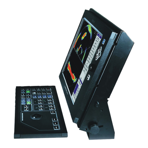
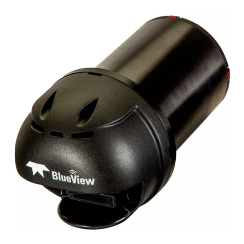
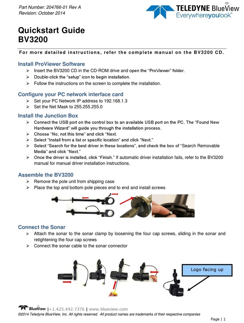
Teledyne BlueView BV3200 User manual

Page | 0
User’s Manual
BV3200 Pole Mount
Part Number: 204765-00
Revision: A, October 2014
© 2014 Teledyne BlueView Technologies, Inc. All rights reserved.
All product names are trademarks of their respective companies.

Page | 1
Table of Contents
Chapter 1: Important Safeguards .......................................................................................2
Chapter 2: System Components........................................................................................3
System Contents........................................................................................................3
System Overview .......................................................................................................4
Chapter 3: Setup & Operation...........................................................................................5
Assemble the Pole......................................................................................................5
Tilt Angle Adjustment...................................................................................................7
Pole Mounting...........................................................................................................7
Junction Box.............................................................................................................8
Installing the Junction Box ............................................................................................9
Final Cable Connections ............................................................................................ 11
Install ProViewer 4 Software........................................................................................ 11
Configure PC .......................................................................................................... 12
Connecting the BV3200 GPS in ProViewer 4....................................................................12
Sonar Angle ........................................................................................................... 15
ProMapper Add-On Software....................................................................................... 16
GPS Heading/Compass Calibration ............................................................................... 16
System Breakdown................................................................................................... 17
Chapter 4: Maintenance................................................................................................ 18
Before Use............................................................................................................. 18
After Use ............................................................................................................... 18
Chapter 5: Troubleshooting............................................................................................ 19
Still not working?...................................................................................................... 20
Appendix A: Technical Specifications................................................................................ 21
Appendix B: Connector Pinouts....................................................................................... 22

Page | 1
Teledyne BlueView, Inc. has made every effort to ensure the accuracy and
completeness of this document; however, because ongoing development efforts are
made to continually improve the capabilities of our products, we cannot guarantee the
accuracy of the contents of this document. We disclaim liability for errors, omissions, or
future changes herein.
©2014 Teledyne BlueView, Inc. All rights reserved. No part of this publication may be
copied, reproduced, or translated, without the prior written consent of Teledyne
BlueView, Inc. No part of this publication may be stored or transmitted in any electronic
form without the prior consent of Teledyne BlueView, Inc. Any unauthorized use is a
violation of copyright laws.
Warning! This device should not be used as a navigational aid to prevent collision,
grounding, boat damage, or personal injury.
Warning! This product contains lead, a chemical known to the state of California to
cause cancer, birth defects and other reproductive harm. Handling and/or opening this
unit may result in exposure to lead, in the form of solder.
Warning! Disassembly and repair of this electronic unit should only be performed by
authorized service personnel. Any modification of the serial number or attempt to repair
the original equipment or accessories by unauthorized individuals will void the warranty.
Warning! Changes or modifications to this unit not expressly approved by the party
responsible for compliance may void the user’s authority to operate this equipment.
Warning! This equipment contains High Voltage electronics. Tampering with or using
damaged equipment could lead to serious injury.
Warranty Information:
The BV3200 is backed by a standard 12-month parts and labor warranty policy. Seller’s
terms and conditions of sale can be found at www.blueview.com
For more information on safety and/or maintenance issues please call Teledyne
BlueView, Inc. at 425.492.7376.

Page | 2
Chapter 1: Important Safeguards
To reduce the risk of electrocution:
Always unplug the BV3200 control box immediately after using. Do not place or store the control box
where it can easily fall or be pulled into water. If the box does fall in the water, unplug before retrieving.
WARNING –To reduce the risk of burns, electrocution, fire, or injury to persons:
1. Use this BV3200 and sonar only for its intended use as described in this manual. Do not use
attachments not recommended by BlueView Technologies.
2. Never operate this product if it has a damaged cord or plug, if it is not working properly, if it has
been dropped or damaged, or if the control box has been dropped into water.
3. Keep cords away from heated surfaces.
4. Connect this product to a properly grounded outlet only. See grounding instructions.
This product should be grounded. In the event of an electrical short circuit, grounding reduces the risk of
electric shock by providing an escape wire for the electric current. The BV3200 control box is equipped
with a cord having a grounding wire with a grounding plug. The plug must be plugged into an outlet that is
properly installed and grounded.
If repair or replacement of the cord or plug is necessary, do not connect the grounding wire to either flat
blade terminal. The wire with insulation having an outer surface that is green with or without yellow stripes
is the grounding wire.
Check with a qualified electrician or serviceman if the grounding instructions are not completely
understood, or if in doubt as to whether the product is properly grounded.
This product is factory equipped with a specific electric cord and plug to permit connection to a proper
electric circuit. Make sure that the product is connected to an outlet having the same configuration as the
plug. No adapter should be used with this product. Do not modify the plug provided—if it will not fit the
outlet, have the proper outlet installed by a qualified electrician. If the product must be reconnected for
use on a different type of electric circuit, the reconnection should be made by qualified service personnel.
If it is necessary to use an extension cord, use only a three wire extension cord that has a three-blade
grounding plug, and a three-slot receptacle that will accept the plug on the product. Replace or repair a
damaged cord.
Page | 3
Chapter 2: System Components
System Contents
You will receive an accessory kit containing the following:
BV3200 Transport Case
Pole Assembly
Junction Box
Pole Mount
7 Ft Ethernet Cable
USB Cable
Power Cable
BV3200 Software and Manuals CD Containing:
- BV3200 QuickStart Guide
- BV3200 User’s Manual
- ProViewer 4 Software
- ProViewer 4 Handbook
- USB Serial Adapter Driver Software
Hex Driver
Screw Kit
Printed BV3200 QuickStart Guide

Page | 4
System Overview
The BlueView BV3200 Mobile Acoustic Underwater Vision® System consists of a boat mountable
BlueView sonar with an adjustable tilt angle, integrated GPS and a compass. The entire system connects
through a single cable to the Junction Box, which then connects to a PC via USB and Ethernet. The
BV3200 system is airline checkable luggage.
To familiarize yourself with the BV3200 system, please review the information in this manual.
BV3200 unit in travel case
BV3200 Components

Page | 5
Chapter 3: Setup & Operation
Assemble the Pole
After verifying that all necessary components are present, you are ready to begin assembly of the
BV3200.
The following instructions will walk you through all steps necessary to assemble the pole, mount the
sonar, and connect all required cabling.
1. Remove the BV3200 pole unit from case.
2. Place the top and bottom pole pieces end to end. Pull the sonar cable through the pole as you
bring the pole bolt flanges together.
3. Rotate one of the pole segments till the alignment notches are adjacent to each other.

Page | 6
4. Attach the lower section to the upper using the provided cap screws. Insert the bolt first through
the unthreaded upper flange and screw into the threaded lower flange.
5. Attach the sonar to the sonar clamp by loosening the four cap screws, sliding in the sonar and
retightening the four cap screws.
6. Connect the sonar cable to the sonar connector.
NOTE: The sonar is inserted into the clamp such that its connector is on the same side
as the Sonar Cable.
NOTE: Use the stickers and connector placement on the rear end cap of the sonar or the
logo on the front end of the sonar to determine the up-down orientation of the sonar. If the
sonar is inverted, be sure to select the “inverted” option in ProViewer’s settings.
Logo facing up

Page | 7
Tilt Angle Adjustment
1. Loosen the clamp angle adjustment knob by turning the knob counterclockwise.
2. Lift the clamp until the angle adjustment selector clears the angle keyway.
3. Select desired angle and tighten the angle adjustment knob by turning clockwise until it is snug.
Pole Mounting
1. Securely attach the transom mount assembly to a fixed structure. The mounting holes are sized
for 1/4” bolts.
2. Place the pole into the clamp and close the clamp by tightening the threaded knob.
3. Rotate the pole in the mount so that the sonar, when set to the ‘home position,’ points in the
desired direction.
4. In order to obtain accurate compass readings, ensure that the arrow on top of the unit is pointed
parallel to the vessel centerline, in the direction of forward travel.
NOTE: It is the user’s responsibility to insure the pole mount is secured in a way that will
support the pole assembly.
NOTE: It is the user’s responsibility to insure the pole mount is secured in a way that
will support the pole assembly.
NOTE: Do not let go of the pole assembly until the clamp is closed and the threads have
fully engaged.

Page | 8
Junction Box
The Junction Box contains a power supply and a USB to RS-485 Converter. The power supply provides
power to both the GPS unit and sonar. The converter adds a COM port to the PC so the PC can receive
GPS data via a USB port. The Ethernet port on the control box provides communication with the sonar.
The Sonar + Junction Box can handle input AC power between 110 and 240 volts.
Ethernet Port to PC:
Sonar Communication
To Pole Assembly
USB Port to PC: GPS and Compass
Communication
AC Power Inlet Port
110-240 VAC

Page | 9
Installing the Junction Box
The Junction Box contains a USB to RS-485 converter and a power supply. The converter will add a
COM port to the PC for communicating with the pan and tilt. The drivers for the converter need to be
installed onto the PC. These drivers are located on the provided CD labeled “BV3200 CD” in the
“Junction Box” folder under “Drivers.”
There are two drivers to install: one is for a “USB Serial Converter”, and the other is for a “USB Serial
Port.”
1. Connect the USB port on the control box to an available USB port on the PC connected to the internet.
The “Found New Hardware Wizard” will guide you through the automatic installation process.
2. First, the USB Serial Converter driver will install. Select “No, not this time” and click “Next.” Follow
prompts until the device is ready to use or cannot be installed.
NOTE: Do not close the second “Found New Hardware Wizard” window while
installing the driver.
NOTE: For Windows Vista, disconnect your PC from the internet before installing
drivers; otherwise, Windows Vista will search for and install the drivers automatically
from Windows Updates and cause errors. The instructions below are for Windows XP.
Installation for Windows Vista may vary from the instructions below.

Page | 10
3. If drives do not install automatically, Insert the BV3200CD into the drive on the PC. In the windows
“Start” menu search for “device manager.” Open “Device Manager.”
4. In Device Manager, under “Other Devices” right click “USB HS Serial Converter” and select “Update
Driver Software.” You will be asked how you want to search for driver software. Select “Browse my
computer for driver software.”
5. Browse to the “BV3200 CD.” “J-Box.” “Drivers,” and select “OK.” Click “Next” and follow screen prompts
to complete driver installation.

Page | 11
Final Cable Connections
1. Connect the sonar and GPS cables to the Junction Box. Connect the Ethernet cable to the control
box, then to an available network connection port on the PC. Verify that all connections in the
diagram below have been made.
2. Connect the power cable to the control box. Connect the opposite end to a suitable AC power
outlet. All necessary connections have now been made.
Install ProViewer 4 Software
Whether connected to an external PC or an onboard AUV controller, the ProViewer software is required
to operate the M-Series Sonar. The following describes how to install the ProViewer 4 software on a user-

Page | 12
supplied PC. For more information on ProViewer and integration, see the ProViewer Software Handbook
found on the BV3200 CD, as well as under the software’s help menu.
Note: Running other applications in conjunction with the ProViewer Software may affect performance of
one or both of the applications.
1) Place the BV3200 CD in the CD-ROM drive and open the “ProViewer 4” folder.
2) Double-click the “setup” icon to begin installation.
3) Follow the instructions on the screen to complete the installation.
Configure PC
The IP address on the user’s PC will need to be set either to “Obtain an IP address automatically,” or to a
static IP: 192.168.1.x where x is any number besides 45 that doesn’t conflict with the user’s system:
Connecting the BV3200 GPS in ProViewer 4
General GPS to ProViewer 4 integration information is provided in the ProViewer 4 software manual. The
information provided below relates directly to establishing communications with the AIRMAR GH2183
GPS mounted inside the BV3200. For more information on ProViewer, integration, and its capabilities,
see the ProViewer Software Handbook found on the software CD.
Descriptions of the functions in the Sonar tab of ProViewer settings are provided below. If connected,
note that values captured from GPS devices will be saved in the .son file while recording, and will be
displayed on the screen both on playback and during live viewing.

Page | 13
COM Port Settings: Select the proper COM port value corresponding to the GPS device USB
connection. Select a baud rate of 4800, data bits of 8, no parity, one stop bit, and no flow control.
NMEA Sequences: The BV-3200 is setup to receive only select NMEA sequences. Under NMEA
Sequences select: HDT, RMC, and ZDA. For more information on NMEA sequences refer to the
ProViewer Software Handbook.
GPS Offset: Because the GPS is mounted directly above the sonar on the BV-3200 the GPS offset will
be zero for both x and y.
Current Configurations: Once COM Port Settings, NMEA Sequences, and GPS Offset have been
configured correctly you save a current configuration using the Add Current button. The current
configuration will appear highlighted under current configurations.
NOTE: This configuration should be stored and populated the next time you open
ProViewer.

Page | 14
Start All: Click this button to begin displaying NMEA information on your ProViewer main window. LAT,
LONG and Heading will be displayed in the lower right hand corner of your ProViewer 4 window.
Stop All: Click this button to stop displaying NMEA information on your ProViewer main window.

Page | 15
Sonar Angle
To achieve optimal performance while imaging targets and/or the bottom at a given depth, the angle that
the sonar is tilted down from the surface is important. This issue is demonstrated in the figures below. On
the left, the sonar is tilted down at a steep angle that provides only a narrow field of view of the bottom.
The sonar on the right-hand figure is set at a much shallower angle that provides both a better
perspective on targets and a larger field-of-view of the bottom. The BV 3200 allows the user to select any
angle from 5 to -20 degrees in 5 degree increments. The table below should be used as a guide for initial
angle selection.
Target Depth (ft)
0
10
20
30
40
60
80
Approx.
Tilt Angle(Deg)
0
5
5-10
10
10
15
20
The sonar’s steep tilt-angle in this figure
produces imagery of a narrow strip of the
bottom.
The sonar’s shallow tilt-angle in this figure
produces an image of the bottom over a broad
area. In general, shallower tilt-angles, which
give larger areas of bottom imaging, are
preferred.
Recommended tilt angles.

Page | 16
ProMapper Add-On Software
Teledyne BlueView offers ProMapper geo-referencing and sonar mosaicking software. ProMapper
enables the users’ ability to display a portion of the standard 2D data window on to a real world
background image or nautical chart. This capability allows the user to easily combine the ease of use of a
Teledyne BlueView forward looking sonar, with practical mapping displays to greatly increase operational
efficiency. The real time map display allows the sonar operator to quickly assess coverage, sonar data
relative to reference points, and interpret the data in the larger context of location and setting. In addition,
because the data is displayed on screen in its true location with a graphical indication of vessel position, it
is easy to reacquire targets quickly for further investigation.
GPS Heading/Compass Calibration
The BV3200 system GPS is factory calibrated for areas without a unique magnetic signature. Depending
on accuracy requirements, it may be desirable to calibrate the BV3200 to its own unique, as-installed
configuration. Additionally, if the GPS Heading/Compass readings become inaccurate, this calibration
step can be used as an attempt to correct the issue. The GPS unit mounted inside the BV3200 has an
auto calibration feature which can be performed by following the steps outlined below.
IMPORTANT: Calibration requires the vessel to complete 2 to 3 circles. The compass should be
calibrated to achieve maximum sensor accuracy. Use of a timer or stop-watch is recommended as the
steps are time-dependent.
Auto Calibration Procedure
1. Install the BV3200 on the vessel with the arrow on the top of the unit pointing parallel to the boat
centerline, and in the direction of forward travel.
2. In calm seas, navigate the vessel to an open area of water, 0.8 km (0.5 mile) of open space away
from other boats or ferrous objects (structures or aids to navigation).
3. Power-cycle the BV3200 junction box.
4. Open ProViewer 4 and display GPS data.
5. Within 2 minutes of cycling the power, steer in a circle at 4 to 6 kts (5 to 7 mph), taking about 2
minutes to complete a circle. Heading information will disappear, indicating that calibration has
begun.
6. Complete 3 to 4 circles, maintaining speed until the Heading information reappears, indicating
that calibration is complete.
If calibration fails, the display will flash Heading ON and OFF in 10 second intervals for 60 seconds.
(Display times may vary by manufacture.)
IMPORTANT: In the event of a calibration failure, repeat the Auto Calibration procedure.
* The optimum rate of turn is 180°/ minute: 3°/second, 30°/10 seconds, 45°/15 seconds, and 90°/30
seconds.

Page | 17
System Breakdown
Proper system breakdown of the BV3200 requires only that the AC power and pole cable be
disconnected from the console, rinse the pole and sonar with fresh water and return to their respective
positions in the carrying case, as shown.
NOTE: Care should be taken to ensure cables are positioned not to crimp or damage
pole components or the cable while shutting the case.

Page | 18
Chapter 4: Maintenance
Before Use
1. Prior to assembly of components, ensure that all connector contacts are clean, dry and free of dirt
and/or corrosion.
2. Inspect all BV3200 hardware for excessive corrosion. Replace as needed.
3. Inspect all cables and connectors for abrasion, cuts or cracks. Repair or replace as needed.
After Use
1. After use rinse all BV3200 components with a solution of mild soap and fresh water. At this time,
inspect all components for corrosion, wear or damage. Replace any piece of hardware showing
corrosion or damage.
Other manuals for BlueView BV3200
1
Table of contents
Other Teledyne Sonar manuals

Teledyne
Teledyne BlueView M Series User manual

Teledyne
Teledyne SeaBat T-Series User manual

Teledyne
Teledyne BlueView BV3200 User manual

Teledyne
Teledyne P series User manual

Teledyne
Teledyne SeaBat T Series User manual

Teledyne
Teledyne Sonar UI SeaBat T Series User manual

Teledyne
Teledyne P series User manual

Teledyne
Teledyne UI User manual