SonicAire MOBILE Series User manual

WARNING
Installation and electrical wiring must be completed by qualified persons in accordance with all applicable codes and standards.
Before servicing or cleaning the unit, disconnect the fan from the power supply and follow proper lock-out-tag-out procedures for your
location. Any cover, guard, or safety device removed for repair must be replaced as originally installed.
Ensure installation securement does not penetrate walls or ceilings where electrical components or wiring could be potentially damaged.
Fan units are not designed or intended to be mounted to movable objects.
All overhead areas must be cleaned and free of dust buildup prior to powering on fan. If fan is not in service, any dust buildup must be
cleaned prior to restarting fan.
SonicAire fans are for the prevention of dust accumulation and are not to be used for declassifying areas with dust accumulation.
Congratulations on selecting the most powerful and
advanced SonicAire fan. Our company wants you to
be 100% satisfied with your purchase. At SonicAire,
we are focused on providing exceptional customer
service. If for any reason you are unsatisfied with your
equipment or have any other questions, we urge you
to give us a call. We have a dedicated staff eager to
assist you with any questions or concerns.
Technical Specifications
Voltage: 110v / 1 Phase, 60 Hz
Motor: 1 HP TEAO Fan
Weight: 450 lbs / 204.1 kg
Oscillation: 120° Vertical Cleaning Radius
Temp Rating: For use up to 55°C/130°F
Model: MobileFlex
OWNER’S MANUAL
MOBILE SERIES FANS
Original Instructions
Please read and save these instructions.
Table of Contents
Safety information 2
General Safety 2
Tip-Over Hazards 2
Electrical Hazards 2
Collision Hazards 2
Setting up your fan 3
Unpacking your fan 3
Inspection and startup 4
Placing your fan 6
Maintaining your fan 8
Fan Parts Warranty 10
LCD screen controls 11
iDrive 13
Wiring diagrams 17

SonicAire MobileFlex
Owner’s Manual
2
Safety information
WARNING: Failure to follow recommended operating and safety procedures may
result in death or serious injury.
We recommend that you manually clean your facility’s overhead area before
turning on the MobileFlex fan. The dust buildup must be reduced to below the
minimum explosive concentration (MEC) level. Disconnect power from ALL other
equipment during start up to prevent a hazardous condition.
General Safety
• Avoid hazardous situations.
• Always perform a pre-operation inspection of the unit.
• Always perform function tests prior to operation.
• Inspect the workplace for safety concerns.
• Only use the fan unit in the manner intended by the manufacturer.
• Ensure that cords and air hoses are maintained in a manner that minimizes trip
hazards.
Tip-Over Hazards
• Do not raise the fan unless the stand is on a firm, level surface.
• Do not raise the fan unless all four legs are locked into the down position and each
caster brake has been locked.
• Do not raise the fan unless each 25lb stability steel ballast has been placed and
secured on each leg of the unit.
• Do not move machine while fan is in raised position.
• Do not raise fan in strong or gusty winds.
• Do not place ladders or scaffolds against any part of this machine.
• Do not use machine on moving objects or vehicles of any kind.
Electrical Hazards
• Do not operate this unit near any overhead electrical current.
• In the event that the unit contacts an energized power source or becomes electrically
charged, DO NOT touch the unit.
Collision Hazards
• Before lowering the fan, ensure the area surrounding the unit is free of obstructions
and personnel.

SonicAire MobileFlex
Owner’s Manual
3
• Inspect the workplace to avoid overhead obstructions or possible hazards.
• Keep the area surrounding the unit free of objects.
• SonicAire encourages the use of a caution barrier around the MobileFlex fan.
Setting up your fan
Figure 1.1
MobileFlex shipping crate
Unpacking your fan
The MobileFlex is shipped resting on its
back as illustrated in Figure 1.1. Please
follow these unpacking instructions to
prevent injury or damage to the unit.
CAUTION: hold the pneumatic lift
stable when removing the top section
of the box, panel, and fan guard. This
will ensure the lift does not rotate. Use
three people to unpack the unit.
1 Remove the side slates and all tie-
down straps from the base pallet.
2 Tilt the front wheels of the cart down to
the ground.
3 Rotate the pallet up until the back
casters are on the ground.
4The control panel is individually
packaged for shipping (Figure 1.1).
Figure 1.2
Control panel installation
Remove the control panel from the
packaging and install it on the mounting
support on the handlebar. Hardware is
shipped inside of the control panel (Figure
1.2).
5 Push in air lines to the top of the panel.
Ensure that the number on the air line
corresponds to the fitting number on the
panel.
6 Connect the female circular connector
from the control panel to the male circular
connector on the hub of the MobileFlex.

SonicAire MobileFlex
Owner’s Manual
4
Attention: Ensure that the decals on the male and female plugs align before
pushing the plugs together. DO NOT FORCE!
Inspection and startup
Figure 1.3
MobileFlex assembly
I. Perform a pre-
operation inspection
1 Be aware of and avoid the
following during start up and
operation:
• Drop-offs or holes
• Bumps, floor obstructions,
or debris
• Sloped surfaces
• Unstable or slippery
surfaces
• Overhead obstructions or
high voltage cables
• Hazardous locations
• Inadequate surface
support to withstand
all load forces imposed by
the machine
• Wind and weather
conditions
2 Ensure that the operator’s
manual is complete, legible and
available for reference.
3 Ensure that all decals are legible and in place.
4 Visually inspect all machine components.
• Circular connector is secure
• Power cable is clear of obstructions
• Compressed air is secured the control panel
• Electrical cables and pneumatic lines are not trip hazards on the floor
• Fan guards are intact and secure

SonicAire MobileFlex
Owner’s Manual
5
II. Start up your fan(s)
1 With the unit in transport mode (Figure 1.6), lower all three support legs and ensure
they are locked in place.
2 Place all switches on the control panel (Figure 1.4) in the “OFF” position and turn the
VFD potentiometer to “0” (Figure 1.5).
3 Connect to a non-GFCI 115v/1ph/60Hz outlet.
4 Press and hold the F4 button. When the fan is fully tilted up and the actuator stops
running, release the F4 button.
MOBILEFLEX
Figure 1.4
MobileFlex control panel
5Press F1 on the keypad once. The display
should read “F1-FAN OFF OSC ON.” The fan
should start to oscillate and rotate. Press the F1
button three more times to stop the fan from
oscillating and rotating. The display should read
“F1-FAN OFF OSC OFF.”
6Press the F1 button twice. The display
should read “F1-FAN ON OSC OFF.” The fan motor
will start slowly and increase to approximately
30% speed (20 Hz). Turn the potentiometer to
“9”; the fan should slowly increase to full speed
(60 Hz). Turn the potentiometer back to “0” to
gradually decrease fan speed to 30%. Note: 30%
is considered minimum speed for the Mobile fan.
7Press the F1 button two more times to stop
Figure 1.5
Variable Frequency
Drive
the fan (Figure 1.4). The display should read “F1-FAN OFF
OSC OFF.”
8Connect 90 psi plant air to the control panel using the
1/4” quick connect fitting. Note: verify pressure gauge on
fan unit does not exceed 40 psi.
9 Press and hold the F3 button. The lift should slowly
rise. Ensure the power cable is free of obstructions when
lifting the unit. Note: ensure both brake feet are in contact
with the floor while the lift is in the raised position.
10 Release the F3 button when the fan reaches the
desired height. Note: ensure the area around the fan is free
of obstructions.

SonicAire MobileFlex
Owner’s Manual
6
11 Press and hold the F3 button again. The fan should begin to descend. Continue to
hold the F3 button until the fan unit has descended completely.
12 Raise the fan back to maximum height by pressing and holding the F3 button again.
13 Press the F1 button three times. The display should read “F1-FAN ON OSC ON.” The
fan should slowly rotate and oscillate during this step.
14 Press the F1 button one more time to stop the fan. Lower the fan as instructed in
step #10.
15 To place the unit in transport mode (Figure 1.6), ensure the display reads “F1-FAN
OFF OSC OFF” and fan has been completely lowered. If necessary, manually rotate
the nozzle of the fan until it is pointed toward the rear of the unit (control panel). This
ensures alignment with the cradle supports. Press and hold the F4 button until the
unit is completely lowered and stops moving. Note: The unit will not tilt until the lift
is fully lowered and brake feet are raised.
Your SonicAire®fan is now ready for operation.
Once the assembly and inspection are complete, you may disconnect the
MobileFlex fan from the power and air sources and move the unit to the desired
location for operation.
Figure 1.6
MobileFlex in transportation mode
Placing your fan
1 Lock all four caster wheels to prevent unit from moving (Figure 1.3).

SonicAire MobileFlex
Owner’s Manual
7
2 Place Caution barriers or cones as required. This is necessary if your fan is located
in a high-traffic area.
3 Plug in 115V cord and connect to plant compressed air hose or portable compressed
air tank.
Note: Ensure that the fan will be able to rotate a full 360° without hitting any object
in the overhead area. Do not locate near any humidifier or adiabetic cooler which
produces free moisture which can get on the fan.
4 Raise fan to desired height for cleaning area.
5 Turn the fan on using the F1 button on the keypad.
6 Set the F1 function to “FAN ON OSC ON” for rotation and oscillation when the fan
is operating.

SonicAire MobileFlex
Owner’s Manual
8
Maintaining your fan
Continuous operation
SonicAire fans are designed so that they can operate continuously. In order for the fan
to create an effective overhead barrier to prevent dust accumulation, the fan MUST be
running during production.
CAUTION: It is the customer’s responsibility to ensure that the fans are operated
frequently enough that a “dust cloud” is not produced by the fan(s). SonicAire fans are
not designed or intended to be used as a “blow down” tool, and should not be used as
such. Dust concentrations must remain below Minimum Explosive Concentration (MEC)
levels.
If the fans will not be operated continuously, they should be operated frequently enough
that when turned on, no visible quantities of dust can be seen in the atmosphere. If dust
is visible when the fan started from a “cold” state, the fan should be operated more
frequently.
Customers should map the facility that the MobileFlex fan is to be used in, and should
identify strategic points of operation. These points should be identified on the map, and
on the floor in the facility. The fan should be moved to all identified positions on a regular
basis to ensure that each location is regularly cleaned. SonicAire recommends creating a
schedule and documentation to ensure this happens on a regular basis.
Electrical information
All owner furnished electrical service and components must meet
the requirements of local/national codes. All SonicAire fans must
have individual circuit protection. Failure to use individual circuit
protection will void the equipment warranty.
CAUTION
The SonicAire fan motor is a three-phase 0.7kw/1 hp motor. The motor operates at 1725
rpm at 60 Hz. The indexing gear motor is 110 volt and runs at 1 rpm (at 60Hz). It is
sealed and rated at 40W. Power is transmitted to the fan motor and gear motor through
a 15 amp slip ring mounted in the unified electrical enclosure (See Wiring Diagrams, p.
16-17).

SonicAire MobileFlex
Owner’s Manual
9
Maintenance schedule
WARNING: Lock out the fan prior to accessing the fan or opening any electrical or
mechanical enclosures.
SonicAire recommends that you complete the following steps every six months:
• Clean and visually inspect your fan for any abnormal conditions or wear.
• Verify that all fasteners (bolts, nuts, etc.) are tight and tighten as required.
• Inspect the gear motor for oil leakage.
• Inspect the upper cylinder (semi-annual) as follows:
1 Plug in MobileFlex fan and connect it to air supply.
2 Using the controls, lift the fan assembly approximately 6 in. (150 mm) and
support the fan assembly so that it can’t be lowered.
3 Disconnect the connecting link from the driven disc by removing the
shoulder bolt (Figure 3.2).
4 Using a hoist, lift the fan assembly approximately 6 inches. Note: hoist
should be approved for lifting a minimum of 250 lbs).
5 Disconnect power and air supply from the unit.
6 Slide all lift cylinders down away from the reinforcing collar.
7 Inspect the upper lift cylinder for any signs of cracking or bulging. Pay
particular attention to the area just below the reinforcing collar.
8 If any issues are observed, remove unit from service and contact SonicAire
Parts and Service.
9 If no damage is observed, the unit can be put back into service.
Once per year we recommend that you:
• Check all electrical connections for proper tightness.
All bearings are sealed or self-lubricated and require no additional lubrication. Although
they require no maintenance they may wear out over time.

SonicAire MobileFlex
Owner’s Manual
10
Fan Parts Warranty
SonicAire equipment comes with a 1-year parts and factory service only warranty. The
warranty begins after the product is shipped from the factory. This should allow sufficient
time for transportation and installation of the fan unit. This warranty is provided to the
original purchaser of the product and is non-transferable.
When the fan unit is installed, operated and maintained in conjunction with other
SonicAire mounting equipment, controls, and accessories according to instructions
included or provided by SonicAire, SonicAire will provide replacement parts and factory
labor to correct defects in materials or workmanship that existed when the fan unit was
purchased, or at its sole discretion replace the unit.
Should you experience any issues with your SonicAire fan unit, please contact SonicAire
guided through some troubleshooting steps and offered the option to receive replacement
parts or return the unit to the factory for repairs. SonicAire replacement parts carry a 1
year warranty.
WHAT IS NOT COVERED
1 Use in a manner that is inconsistent with SonicAire’s user, operator, or installation
instructions.
2 Service or parts to correct improper installation, maintenance, or installation not in
accordance with electrical codes or safety standards.
3 Parts for conversion of fan unit to different operational voltage than was originally
ordered.
4 Damage from unapproved environmental conditions, accident, misuse, abuse, fire,
floods, or acts of God.
5 Damage from use in conjunction with products not approved by SonicAire.
6 Repairs to parts or fan unit to correct product damage or defects caused by improper
service, alteration or modification of the fan unit.
7 Cosmetic damage including scratches, dents, chips,and other damage to the fan unit
finishes, unless such damage results from defects in materials and workmanship
and is reported to SonicAire within 45 days of shipment from factory.
8 Discoloration, rust, or oxidation of surfaces resulting from caustic or corrosive
environments including but not limited to high salt concentrations, high moisture or

SonicAire MobileFlex
Owner’s Manual
11
humidity, exposure to chemicals, or elevated ambient temperatures. Standard Pro
Series fans are warrantied to 130°F/55°C. Extreme Temperature Fans and Parts are
available for warrantied parts to 170°F/75°C. Contact SonicAire Parts and Service
at 1-336-712-2437 for more information.
9 Housekeeping expenses due to inoperative condition of a fan unit.
10 On-site field labor, removal, re-installation, or shipping costs of returning fan unit
back to factory for repairs.
The cost of the repair or replacement under any of these excluded circumstances shall
be borne by the customer.
LCD screen controls
-MOBILE FLEX--MOBILE FLEX-
REMAINING TIME00:00hREMAINING TIME00:00h
F1-FAN OFF OSC-OFFF1-FAN OFF OSC-OFF
F2-TIMER OFF 01:30hF2-TIMER OFF 01:30h
F3-LIFT ENABLEDF3-LIFT ENABLED
F4-TILT ENABLEDF4-TILT ENABLED
The Mobile control panel is equipped
with a keypad and LCD Screen Control
System for programming and operating
your Mobile fan. Use the information in
this section to understand the functions
and features associated with the LCD
Panel Control System.
FUNCTION 1: Turning your fan on and o
Figure 2.1
Turning your Mobile fan ON and
OFF
Pressing the F1 button will cycle through
the on/off settings for Oscillation and Fan
Motor Operation. Press the F1 button
once, as shown in Figure 2.1, to turn on
fan oscillation. Press the F1 button again
to turn off oscillation and turn on fan.
Press the F1 button again to turn both
oscillation and fan on together. Press F1
again to turn off both.
F1 (1x): Fan OFF,Oscillation ON
F1 (2x): Fan ON,Oscillation OFF
F1 (3x): Fan ON,Oscillation ON
F1 (4x): Fan OFF,Oscillation OFF

SonicAire MobileFlex
Owner’s Manual
12
Figure 2.2
Adjusting the run timer (hour:minute
designation highlighted)
FUNCTION 2: Run timer
Press F2 to cycle through the on/off
settings for the run timer. This function
operates a countdown timer for how
long the fan will operate. To change the
time of operation, press and hold the ESC
button until the hour:minute designation
is highlighted. Press ENTER to highlight
the individual time selection. Use the up/
down arrows to set the desired run time.
When done press ENTER.
Figure 2.3
Raising and lowering the pneumatic
lift
FUNCTION 3: Lift
operation
Press and hold the F3 button to raise the
pneumatic lift and deploy the brakes.
Press and hold the F3 button again to
lower the lift.
Note: The F3 button must be held until
the desired height is achieved. Once
returned to the lowest position, the
brakes will release.
Figure 2.4
Flex operation
FUNCTION 4: Flex
operation
Press and hold the F4 button to tilt the fan
to the cleaning position. Press and hold
the F4 button again to lower the fan to
the travel position.
Note: The F4 button must be held until the
desired tilt is achieved. The MobileFlex is
designed to only be utilized in the fully
upright position for cleaning or the fully
tilted position for travel.
SonicAire MobileFlex
Owner’s Manual
13
Control wiring diagram
iDrive
The iDrive system allows you to adjust the preferred cleaning area by changing the
vertical oscillation angle. The iDrive system (Figure 2.1) allows the user to make simple
adjustments to achieve a custom cleaning angle.
Connecting Link
The Connecting Link connects the Drive and Driven Discs. Figure 1.6 shows the proper
assembly order of the Connecting Link.
Drive Disc
The Drive Disc is located at the top of the iDrive assembly. This disc determines the
magnitude of oscillation.
Driven Disc
The Driven Disc is located at the bottom of the iDrive assembly. This disc determines
where the fan nozzle angle will be directed.
Each setting consists of an alphanumeric combination that indicates where to install the
Connecting Link as shown in Figure 2.1 (see Page 13 for additional settings).

SonicAire MobileFlex
Owner’s Manual
14
3
3
-
-
Y
Y
J
J
Standard Oscillation
Connecting
Link
Drive Disc
Driven Disc
Figure 2.1
Standard oscillation setting for Mobile fan
Changing the settings
1 After reviewing the angle illustrations to decide which setting would be ideal for
your facility, choose a setting from the list on page 15.
Note: For additional oscillation settings, see the Additional iDrive Options section
or contact SonicAire Parts and Service at 1-336-712-2437 or at partsandservice@
sonicaire.com.

SonicAire MobileFlex
Owner’s Manual
15
2The fan nozzle must be positioned to the right of the fan when viewing the iDrive for
3
3
-
-
Y
Y
J
J
Standard Oscillation
all hanging mounts (to the left
for standing mounts).
3 While supporting the
fan nozzle, disconnect the
Connecting link from the Drive
Disc by loosening the locknut on
the end of the shoulder bolt.
4 Review your Oscillation
Setting for the Drive Disc
position. This will be the first
character in the setting and will
be a numerical digit.
5
5
-
-
Y
Y
I
I
Maximum Oscillation
5Install the shoulder bolt into
the specified opening by
threading the bolt through the
disc.
6 Secure the bolt with the
locknut removed in step #3 and
torque bolt to 15 ft-lbs.
7 Proceed to the Driven Disc
end of the Connecting Link and
remove the locknut from the
end of the shoulder bolt.
8 Review your setting to
determine the proper attachment position on the Driven Disc. The second and third
digits in the setting combination defines the Driven Disc connection.
9 Determine which side of the Driven Disc you will be attaching the Connecting Link.
Review the decal and ascertain the appropriate side for your mount option.
10 Find the indicated row on the Driven Disc from your chosen setting. This will be the
second digit in the setting (Y or Z).
11 Find the hole within the selected row that corresponds with the third digit in your
setting selection (A-N).
12 Thread the shoulder bolt into the designated hole while ensuring the correct

SonicAire MobileFlex
Owner’s Manual
16
assembly order of parts (Figure 1.6).
13 Install the locknut removed in Step #8 and torque bolt to 15 ft-lbs.
iDrive setting options
Each of these illustrations depicts a different setting and a color coded diagram indicating
the relationship between the setting character and the Connecting Link attachment
position on each the Drive and Driven Discs.
Important: Contact SonicAire for assistance if you are not certain of your selection or
simply want to confirm your selection process. Warning: Improper attachment of the
Connecting Link may result in equipment damage!
NOTE: Always use Standing Mount settings for MobileFlex fan.

SonicAire MobileFlex
Owner’s Manual
17
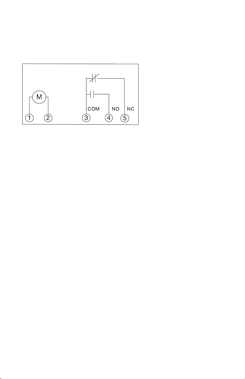
Wiring diagrams
Mobile fan wiring diagram
MobileFlex
Motor (hp) 1
Gearmotor (W) 40
Fuse (A) 110v 1
Capacitor (µF) 10
** Use Class CC Fuse
VFD
Gnd
Fan Enclosure
Fuse**
Circular
Connector
1
52
3
4
Capacitor
Slip Ring
Fan Motor
Cable
FAN MOTOR GEAR
MOTOR
TB
TBTB
TB
TB
TB
BL
BLRBK
BK
BK BKW
R
W
BKBL
NL 1
R
R
R
BK
Primary Motor
Overload
Protection
and LOTO
Disconnect
Provided by
Others
Other manuals for MOBILE Series
1
This manual suits for next models
1
Table of contents
Other SonicAire Fan manuals


Popular Fan manuals by other brands


Monte Carlo Fan Company
Monte Carlo Fan Company 3SY52 D Series Owner's guide and installation manual

Emerson
Emerson APOLLO CF3900AB01 owner's manual

Stulz
Stulz Air Booster 2 operating instructions

Unold
Unold 86880 Instructions for use

Chore-Time
Chore-Time E-Z Installation and operation instructions

Broan
Broan ZB110ML installation guide