SonicAire AutoSweep 205 User manual

WARNING
Installation and electrical wiring must be completed by qualified persons in accordance with all applicable codes and standards.
Before servicing or cleaning the unit, disconnect the fan from the power supply and follow proper lock-out-tag-out procedures for your
location. Any cover, guard, or safety device removed for repair must be replaced as originally installed.
Ensure installation securement does not penetrate walls or ceilings where electrical components or wiring could be potentially damaged.
Fan units are not designed or intended to be mounted to movable objects.
All overhead areas must be cleaned and free of dust buildup prior to powering on fan. If fan is not in service, any dust buildup must be
cleaned prior to restarting fan.
SonicAire fans are for the prevention of dust accumulation and are not to be used for declassifying areas with dust accumulation.
Congratulations on selecting the most powerful and
advanced SonicAire fan. Our company wants you to
be 100% satisfied with your purchase. At SonicAire,
we are focused on providing exceptional customer
service. If for any reason you are unsatisfied with your
equipment or have any other questions, we urge you
to give us a call. We have a dedicated staff eager to
assist you with any questions or concerns.
Technical Specifications
Voltage: 230v, 460v, 575v / 3 Phase, 60 Hz
Motor: 2 HP TEAO Fan
Weight: 200 lbs
Oscillation: 120° horizontal cleaning radius
Temp Rating: For use up to 55°C/130°F
Model: AutoSweep 205 (AS205)
OWNER’S MANUAL
AUTOSWEEP
Original Instructions
Please read and save these instructions.
Table of Contents
Setting up your fan 2
Placing your fan 2
Installing your fan 3
Maintaining your fan 7
Continuous operation 7
Electrical information 7
Maintenance schedule 8
Fan Parts Warranty 8
iDrive 10
Changing the settings 11
Additional iDrive options 12
Wiring diagrams 15
SonicAire fan wiring diagram 15
Multiple fan wiring diagram 16
Troubleshooting 17

SonicAire AutoSweep
Owner’s Manual
2
Setting up your fan
Your SonicAire Pro Series fan comes completely assembled. The parts needed for
installation are included in your package unless otherwise noted. If you have chosen
additional accessories for your fan, please refer to the corresponding accessory manual
for instructions regarding installation and operation.
Placing your fan
We recommend that you manually clean your installation area before turning on
your fan(s). The dust build up must be reduced to below the minimum explosive
concentration (MEC) level. Disconnect power from ALL OTHER equipment during
start-up to prevent a hazardous condition.
Ensure the chosen structure is suitable to support a 250lb (115kg) load (SonicAire
recommends consulting with a structural engineer prior to installing the fan or penetrating
structural elements).
DO NOT locate the fan near humidifiers or adiabatic coolers that produce free moisture
(water) that may accumulate on the fan.
If you need assistance with a layout or system design to make sure the effective cleaning
distance is not exceeded, please contact SonicAire.
DO NOT use this fan with any solid state speed device.
Determine where you will mount your fan. Use the dimensions in Figure 1.1 to ensure
the fan has clearance to oscillate 120° without colliding with any nearby objects. Please
allow 6 inches of clearance in all directions.
Tip: For large overhead obstructions, locate fans on each side of the objects to achieve
maximum cleaning capacity.

SonicAire AutoSweep
Owner’s Manual
3
Side View Front View
Top View
Figure 1.1
AutoSweep Dimensions
Installing your fan
I. Install the fan mounting plate
The SonicAire AutoSweep comes equipped with a base mounting plate, which can be
used to mount the fan to a permanent structure such as a floor, I-beam or mezzanine
grate. Hardware is not included and can be purchased from SonicAire or independently
sourced and specified by a structural engineer affiliated with the customer or installer.

SonicAire AutoSweep
Owner’s Manual
4
Figure 1.2
Floor-mounting scenario
Figure 1.3
Typical I-beam installation
Figure 1. 2 shows a typical installation into a floor or mezzanine.
Figure 1. 3 shows a typical I-beam installation.
The fan shroud can be elevated or lowered depending on facility needs. SonicAire
recommends strut or custom shims for such an application. Regardless of installation
choice, the AutoSweep Fan should always be mounted in a four point configuration for
safe operation.
II. Connect the iDrive
The iDrive is disconnected for shipping purposes. For step by step instructions on the
initial setup of the iDrive follow the directions below.
1 Identify the iDrive door on the side of the fan by locating the tag in Figure 1.5.
Figure 1.4
Correct order of
connecting link shoulder
bolt and hardware
2 To access the iDrive, open the door by releasing
the 1/4 turn fasteners.
3 Locate the Connecting Link.
The top most end of the Connecting Link (Drive Disc)
should be attached from the factory to the appropriate
position on the Drive Disc.
4 Locate the bottom most end of the Connecting
Link. The hardware necessary for attachment (Figure
1.4) is already installed, in the correct order, on the end
SonicAire AutoSweep
Owner’s Manual
5
of the Connecting Link.
Figure 1.5 Figure 1.6
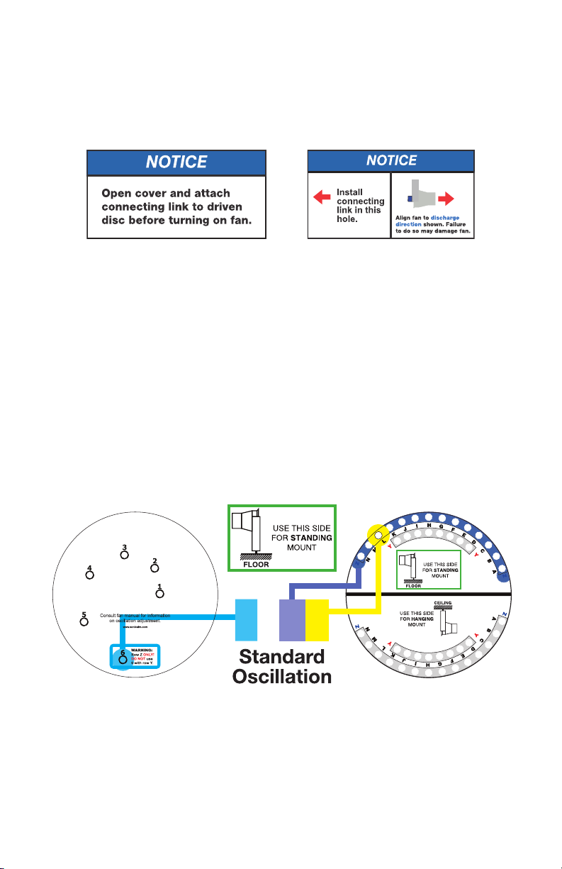
5 Locate the NOTICE tag in Figure 1.6. This tag indicates the Driven Disc hole in which
you need to attach the Connecting Link.
6 Remove the locknut from the back side of the Connecting Link.
7 Remove the NOTICE tag from the hole in the Driven Disc and thread the end of the
shoulder bolt through the Driven Disc.
8 Reinstall the locknut on the end of shoulder bolt and torque to 15 ft-lbs.
Note: All fans are set to Standard Oscillation (See Figure 1.7 and Figure 2.1) from the
factory. For information regarding custom oscillation settings refer to Additional iDrive
Options on page 8.
--
6ZL
Figure 1.7
Standard oscillation setting for AutoSweep
WARNING: INSTALLING THE CONNECTING LINK IN THE INCORRECT HOLES
WILL CAUSE THE KEYS TO SHEAR AND CAN CAUSE POTENTIAL GEAR MOTOR
FAILURE. WARRANTY DOES NOT COVER FAILURES ASSOCIATED WITH INCORRECT

SonicAire AutoSweep
Owner’s Manual
6
CONNECTING LINK PLACEMENT. PLEASE CONTACT SONICAIRE IF YOU HAVE ANY
QUESTIONS REGARDING THE PROPER PLACEMENT OF THE CONNECTING LINK.
III. Connect the TBE (Terminal Block Enclosure)
CAUTION: All electrical wiring (by owner) must be designed and installed in
accordance with local/national electrical codes (NEC NFPA 70).
Figure 1.8
1 Secure the enclosure to the building structure using the mounting holes on the
outside of the enclosure.
2 Use correct fittings for field wiring type and connect field wiring fittings or conduit
to the TBE.
3 Install conductors as indicated in Figure 1.8.
IV. Start up your fans
1 Turn ON the power to each fan one at a time.
2 Check for proper rotation of the fan blades.
3 If the air is not blowing out of the fan discharge, change two of the electrical leads
at the local disconnect switch to change the direction of the fan rotation.
4 Observe the fan as it oscillates through one complete cycle to ensure the fan has
proper clearance and there is no apparent binding of the iDrive system.
Your SonicAire®fan is now ready for operation.

SonicAire AutoSweep
Owner’s Manual
7
Maintaining your fan
Continuous operation
SonicAire fans are designed so that they can operate continuously. In order for the fan
to create an effective overhead barrier to prevent dust accumulation, the fan MUST be
running during production.
CAUTION: It is the customer’s responsibility to ensure that the fans are operated
frequently enough that a “dust cloud” is not produced by the fan(s). SonicAire fans are
not designed or intended to be used as a “blow down” tool, and should not be used as
such. Dust concentrations must remain below Minimum Explosive Concentration (MEC)
levels.
If the fans will not be operated continuously, they should be operated frequently enough
that when turned on, no visible quantities of dust can be seen in the atmosphere. If dust
is visible when the fan started from a “cold” state, the fan should be operated more
frequently.
The SonicAire fan is designed to operate continuously. The fan discharge will oscillate
through the chosen angle as determined by the iDrive settings.
Electrical information
All owner furnished electrical service and components must meet
the requirements of local/national codes. All SonicAire fans must
have individual circuit protection. Failure to use individual circuit
protection will void the equipment warranty.
CAUTION
The SonicAire Pro200 fan motor is a three-phase 1.5kw/2 hp motor (or a 0.75kW/1 hp
motor for the Pro100 Series). The motor operates at 1725 rpm at 60 Hz. The indexing
gear motor is a sealed three phase, 12W, 1/56 HP motor running at 0.7 RPM (at 60Hz).
Power is transmitted to the fan motor and gear motor through a 30 amp slip ring mounted
in the unified electrical enclosure (See Wiring Diagrams, p. 12-13).

SonicAire AutoSweep
Owner’s Manual
8
Maintenance schedule
Recommended Preventive Maintenance Schedule
Industry Schedule Exceptions
Textile 12 months
Wood 9 months 6 months in damp environments
Gypsum 9 months
Paper 12 months 6 months in damp environments
Plastics 12 months
Chemical 9 months
Agricultural 12 months
Pharmaceutical 9 months
Recycling 12 months
WARNING: Lock out the fan prior to accessing the fan or opening any electrical or
mechanical enclosures.
SonicAire recommends that you complete the following steps every six months:
• Clean and visually inspect your fan for any abnormal conditions or wear.
• Verify that all fasteners (bolts, nuts, etc.) are tight and tighten as required.
• Inspect the gear motor for oil leakage.
Once per year we recommend that you:
• Check all electrical connections for proper tightness.
All bearings are sealed or self-lubricated and require no additional lubrication. Although
they require no maintenance they may wear out over time.
Fan Parts Warranty
SonicAire equipment comes with a 1-year parts and factory service only warranty. The
warranty begins after the product is shipped from the factory. This should allow sufficient
time for transportation and installation of the fan unit. This warranty is provided to the
original purchaser of the product and is non-transferable.

SonicAire AutoSweep
Owner’s Manual
9
When the fan unit is installed, operated and maintained in conjunction with other
SonicAire mounting equipment, controls, and accessories according to instructions
included or provided by SonicAire, SonicAire will provide replacement parts and factory
labor to correct defects in materials or workmanship that existed when the fan unit was
purchased, or at its sole discretion replace the unit.
Should you experience any issues with your SonicAire fan unit, please contact SonicAire
guided through some troubleshooting steps and offered the option to receive replacement
parts or return the unit to the factory for repairs. SonicAire replacement parts carry a 1
year warranty.
WHAT IS NOT COVERED
1 Use in a manner that is inconsistent with SonicAire’s user, operator, or installation
instructions.
2 Service or parts to correct improper installation, maintenance, or installation not in
accordance with electrical codes or safety standards.
3 Parts for conversion of fan unit to different operational voltage than was originally
ordered.
4 Damage from unapproved environmental conditions, accident, misuse, abuse, fire,
floods, or acts of God.
5 Damage from use in conjunction with products not approved by SonicAire.
6 Repairs to parts or fan unit to correct product damage or defects caused by improper
service, alteration or modification of the fan unit.
7 Cosmetic damage including scratches, dents, chips,and other damage to the fan unit
finishes, unless such damage results from defects in materials and workmanship
and is reported to SonicAire within 45 days of shipment from factory.
8 Discoloration, rust, or oxidation of surfaces resulting from caustic or corrosive
environments including but not limited to high salt concentrations, high moisture
or humidity, exposure to chemicals, or elevated ambient temperatures. Fans are
warrantied to 130°F/55°C. Contact SonicAire Parts and Service at 1-336-712-2437
for more information.
9 Housekeeping expenses due to inoperative condition of a fan unit.
10 On-site field labor, removal, re-installation, or shipping costs of returning fan unit
back to factory for repairs.
SonicAire AutoSweep
Owner’s Manual
10
The cost of the repair or replacement under any of these excluded circumstances shall
be borne by the customer.
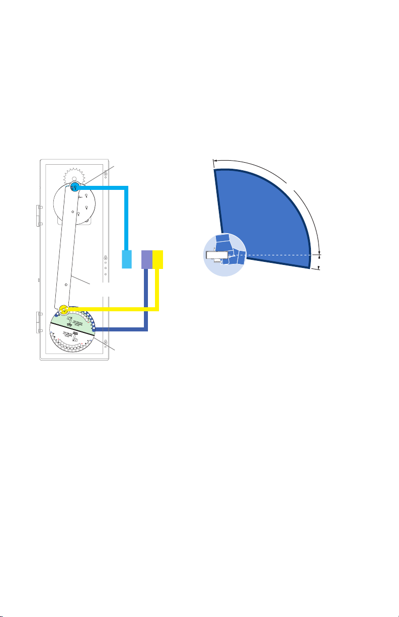
iDrive
--
6ZL
Figure 2.1
Standard oscillation setting for AutoSweep
Standard
Oscillation
107° coverage
97°
9°
Drive
disc
Driven
disc
Connecting
link
The iDrive system allows you to adjust the preferred cleaning area by changing the
vertical oscillation angle. The iDrive system (Figure 2.1) allows the user to make simple
adjustments to achieve a custom cleaning angle.
Connecting Link
The Connecting Link connects the Drive and Driven Discs. Figure 1.6 shows the proper
assembly order of the Connecting Link.
Drive Disc
The Drive Disc is located at the top of the iDrive assembly. This disc determines the
magnitude of oscillation.
Driven Disc
The Driven Disc is located at the bottom of the iDrive assembly. This disc determines
where the fan nozzle angle will be directed.
Each setting consists of an alphanumeric combination that indicates where to install the

SonicAire AutoSweep
Owner’s Manual
11
Connecting Link as shown in Figure 2.1 (see Page 12 for additional settings).
Changing the settings
1 After reviewing the angle illustrations to decide which setting would be ideal for
your facility, choose a setting from the list on page 12.
Note: For additional oscillation settings, see the Additional iDrive Options section
or contact SonicAire Parts and Service at 1-336-712-2437 or at partsandservice@
sonicaire.com.
2 The fan nozzle must be positioned to the right of the fan when viewing the iDrive for
all hanging mounts (to the left for standing mounts).
3 While supporting the fan nozzle, disconnect the Connecting link from the Drive Disc
by loosening the locknut on the end of the shoulder bolt.
4 Review your Oscillation Setting for the Drive Disc position. This will be the first
character in the setting and will be a numerical digit.
5 Install the shoulder bolt into the specified opening by threading the bolt through the
disc.
6 Secure the bolt with the locknut removed in step #3 and torque bolt to 15 ft-lbs.
7 Proceed to the Driven Disc end of the Connecting Link and remove the locknut from
the end of the shoulder bolt.
8 Review your setting to determine the proper attachment position on the Driven
Disc. The second and third digits in the setting combination defines the Driven Disc
connection.
9 Determine which side of the Driven Disc you will be attaching the Connecting Link.
Review the decal and ascertain the appropriate side for your mount option.
10 Find the indicated row on the Driven Disc from your chosen setting. This will be the
second digit in the setting (Y or Z).
11 Find the hole within the selected row that corresponds with the third digit in your
setting selection (A-N).
12 Thread the shoulder bolt into the designated hole while ensuring the correct
assembly order of parts (Figure 1.6).
13 Install the locknut removed in Step #8 and torque bolt to 15 ft-lbs.

SonicAire AutoSweep
Owner’s Manual
12
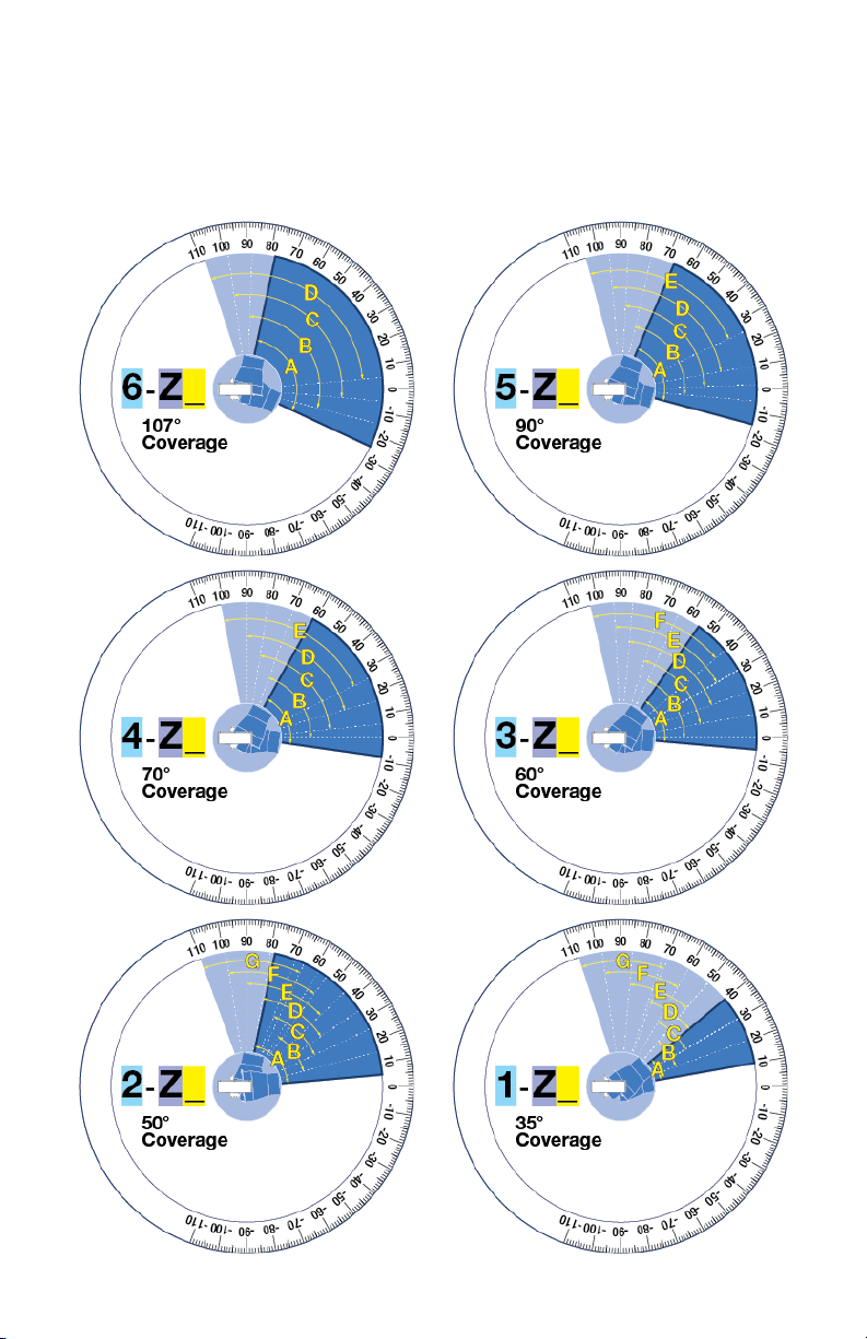
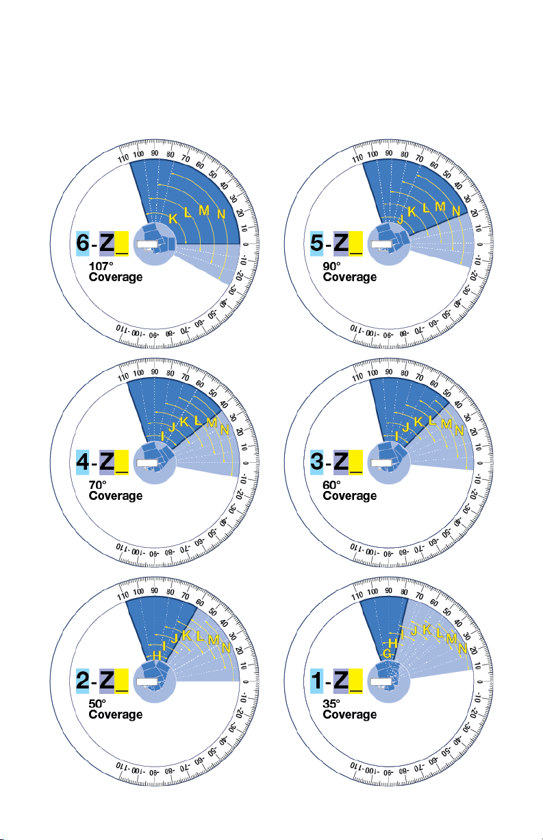
Additional iDrive options
Each of the following fan diagrams illustrates a range of oscillation settings for a
particular Drive Disc number (1-6) and Driven Disc axis (Y or Z) combination. This
combination determines how wide the vertical oscillation radius will be. The final iDrive
setting selection - the Driven Disc letter (A-N)(A-N) - determines the extent angles of the
oscillation radius.
SonicAire AutoSweep
Owner’s Manual
13
Options for “Hanging” side of driven disc
SonicAire AutoSweep
Owner’s Manual
14
Options for “Standing” side of driven disc
SonicAire AutoSweep
Owner’s Manual
15
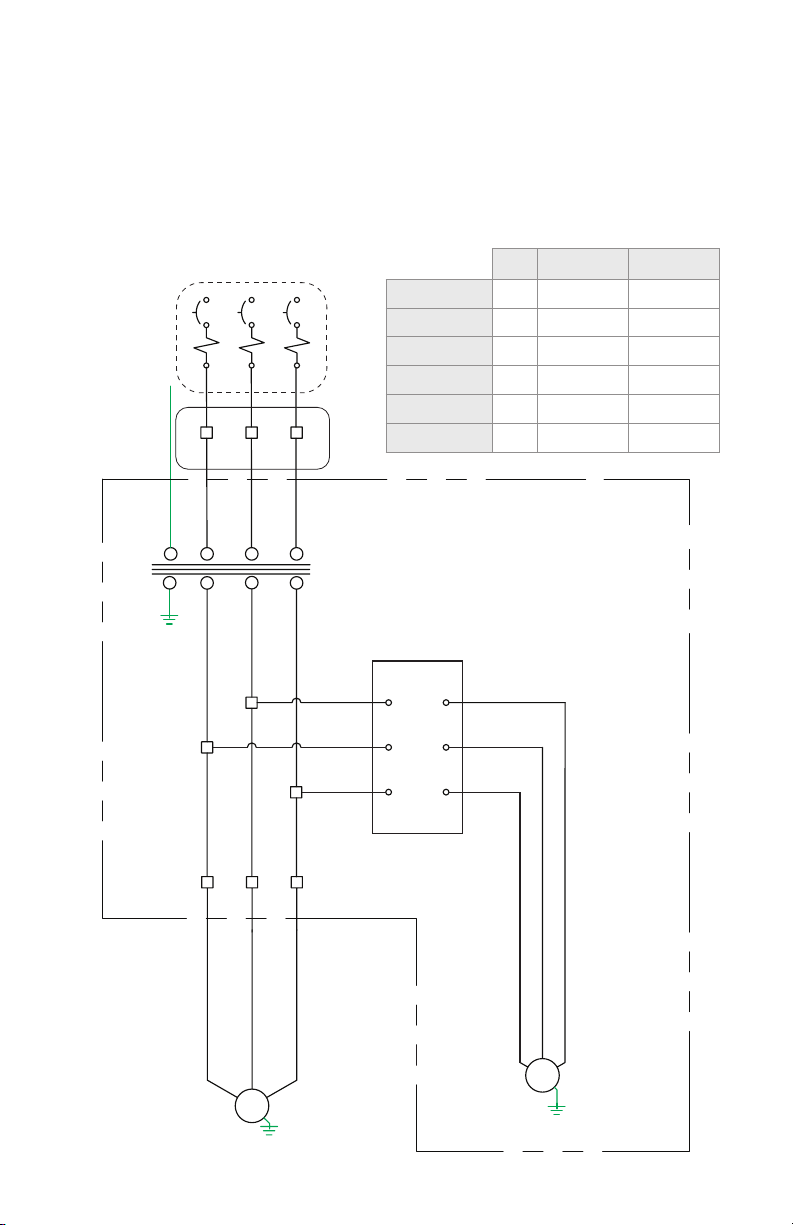
Mini Pro100/105 Pro200/205
Motor (hp) 1 1 2
Gearmotor (W) 10 10 10
MSP (230v) 0.14 0.14 0.14
MSP (380v) 0.14 0.14 0.14
MSP (480v) 0.11 0.11 0.11
MSP (575v) N/A 0.1 0.1
Wiring diagrams
SonicAire fan wiring diagram
Slip Ring
MSP
Fan Motor
Cable
Gnd
TBE
FAN MOTOR
GEAR MOTOR
TB
TB
TB
TB
TB
TB
TB
TB
TB
BL R
R
BL
BK
BK BL R
BK
Fan Enclosure
Primary Motor
Overload
Protection
and LOTO
Disconnect
Provided by
Others

SonicAire AutoSweep
Owner’s Manual
16
Pro100 (380v)
Pro105 (380v)
Pro200 (380v)
Pro205 (380v)
XT200 (380v)
Motor (hp) 1 2
Amperage (at 380v) 1.8 3.3
Multiple fan wiring diagram
B
R
Bk
Fan Motor
Fan #1
Fan Motor
Fan #2
Fan Motor
Fan #3
Overload Heaters
Motor Starter/
Local Protection
Provided by
Others
Power Contacts
Properly Sized
Conductors
Properly
Sized
Conductors
380v, 3 phase, 50Hz
power from circuit
breaker or control panel
Additional fans
on same circuit
Multiple SonicAire Fans on the same circuit
TBE TBE TBE

SonicAire AutoSweep
Owner’s Manual
17
Troubleshooting
Problem Cause Solution
Fan blade rotation
is reversed/
fan is blowing
backwards
Fan is field wired
incorrectly
1. Turn off and LOTO the power to the fan at the main disconnect.
2. Switch off Local Disconnect and open enclosure.
3. Disconnect the L1 & L3 conductors.
4. Reverse the L1 & L3 conductor connections on the load side of the
switch and reconnect.
5. Close local disconnect and power on fan and check for proper fan
blade rotation.
Fan is not
oscillating
correctly/Fan is
not oscillating at
the chosen angle
Connecting link
is improperly
attached
1. Verify that the connecting link is attached properly by referring to the
iDrive instructions in your fan manual (Pg 4-5).
2. Review the instruction on the driven disc decal for “hanging” and
“standing” mounts and verify that you have the correct setting
depending on your mount option.
Note: Review Fan Discharge Direction decals for proper orientation.
Fan will not start Power is not
reaching the fan
1. Check building supply.
2. Check all three phases to the fan for power.
3. Check to ensure the conductor insulation has not been clamped within
the terminal block.
Fan oscillates but
does not rotate or
free spins
Broken drive
chain or loose set
screws
1. Check the iDrive chain located behind the driven disc.
2. If chain is broken, call SonicAire for a replacement.
3. If chain is intact, check the set screws on the sprockets and top gear to
for proper tightness.
4. If set screws are tight, check top gear to jackshaft idler gear
engagement.
5. If top gear does not engage jackshaft idler gear, loosen set screws and
adjust top gear to engage idler gear.
6. Tighten top gear set screws.
Fan rotates but
does not oscillate
Connecting link
is improperly
attached/loose set
screws or missing
shaft keys
1. Check the connecting link to make sure it is properly attached. Please
refer to the iDrive section of your fan manual for instructions on
attaching the connecting link (Pg 4-5).
2. Check the set screws on the driven disc for tightness.
3. If you are missing shaft keys, please contact SonicAire for a
replacement.
Fan does not
oscillate or rotate
Gear motor issue
or damaged drive
disc
1. Check the gear motor for tripping/conductivity.
2. If no issue is found with the gear motor, inspect the drive disc for
damage.
3. If drive disc is not damaged, check for tripping of open motor
protection equipment.
4. If motor protection equipment does not need to be reset, contact
SonicAire Tech Support.
If the above solutions do not correct or address the problem, please contact SonicAire Parts & Service at
when contacting Parts & Service.
This manual suits for next models
1
Table of contents
Other SonicAire Fan manuals


Popular Fan manuals by other brands


STI
STI EZ-Path 44+ Series Installation sheet

Prem-I-Air
Prem-I-Air EH1852 user manual

Westinghouse
Westinghouse ETL-ES-Alta Vista-WH22 owner's manual

Titus
Titus DVCP Installation and operation manual

LUCCI
LUCCI AIRFUSION BREEZE installation instructions

Manrose
Manrose MRUF150WH Installation and wiring instructions