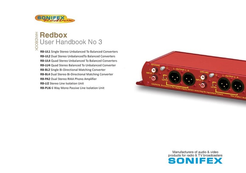
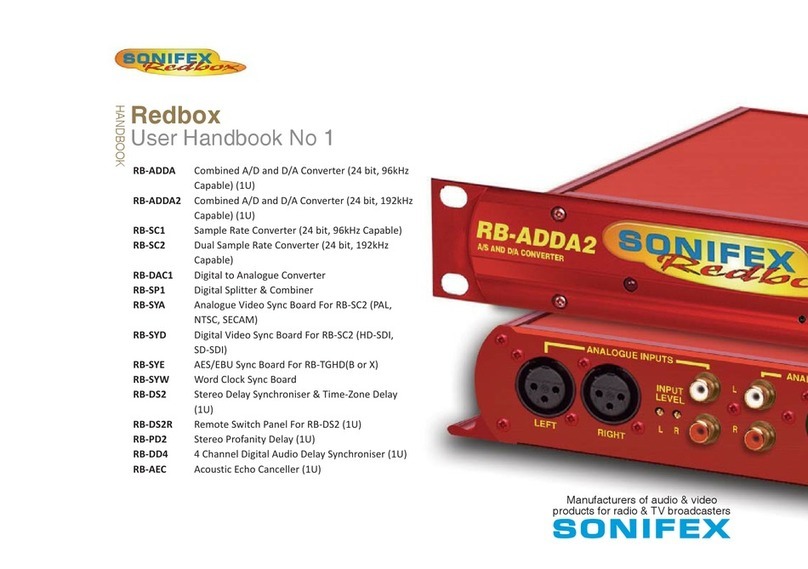
Sonifex Redbox RB Series Instruction Manual

Digital Audio Converters, Synchronisers, Delays
& Silence Detectors
RB-ADDA Combined A/D and D/A unit (24 bit, 96kHz
capable)
RB-ADDA2 Combined A/D and D/A unit (24 bit, 192kHz
capable)
RB-SC1 Sample rate converter (24 bit, 96kHz capable)
RB-SC2 Dual sample rate converter (24 bit, 192kHz capable)
RB-DAC1 Digital to analogue converter
RB-SP1 Digital AES/EBU splitter & combiner unit
RB-DS2 Stereo audio delay synchroniser
RB-PD2 Stereo profanity delay
RB-SD1 Silence detection unit
RB-DSD1 Digital silence detection unit
Redbox
User Handbook No 1

b
Redbox User Handbook No 1
Revision 2.13 June 2012
©Sonifex Ltd, 2000-12
All Rights Reserved
Sonifex Ltd, 61, Station Road, Irthlingborough,
Northants, NN9 5QE, England.
Tel : +44 (0)1933 650 700
Fax : +44 (0)1933 650 726
Web : http://www.sonifex.co.uk
Information in this document is subject to change without notice and does not represent
a commitment on the part of Sonifex Ltd. Sonifex Ltd shall not be liable for any loss or
damage whatsoever arising form the use of information or any error contained in this
manual.
No part of this manual may be reproduced or transmitted in any form or by any means,
electronic or mechanical, including photocopying, recording, or information storage and
retrieval systems, for any purpose other than the purchaser’s personal use, without the
express written permission of Sonifex Ltd.
Unless otherwise noted, all names of companies, products and persons contained herein are
part of a completely ctitious adaptation and are designed solely to document the use of
Sonifex products.

Redbox User Handbook No 1
c
CONTENTS
CONTENTS
Warranty i
Warranty and Liability - important the purchaser is advised to read this clause i
Unpacking the Redbox ii
Warranty Registration iii
Safety Information iii
Safety of Mains Operated Equipment iii
Voltage Setting Checks iii
Fuse Rating iii
Power Cable and Connection iv
Ordering the Correct Mains Lead iv
Installation Information iv
Installing the Optional Video Sync Boards in the RB-DSD1 vi
Opening the RB-DSD1 vi
WEEE & RoHS Directives - Sonifex Statement viii
1 RB-ADDA Combined A/D and D/A Converter 1
Introduction 1
System Block Diagram 2
Front Panel Indicators 2
Rear Panel Connections and Operation 2
Technical Specications RB-ADDA 7
2 RB-ADDA2 Combined A/D and D/A Converter 24bit 192kHz 8
Introduction 8
Master Mode 9
Slave Mode 9
Auto Mode 9
Auto Lock Mode 9
System Block Diagram 10
Front Panel Controls & Indicators 10
Rear Panel Connections and Operation 11
Serial Port Control 14
Serial Interface Commands and Responses 14
Upgrading Firmware 17
Technical Specications RB-ADDA2 17
3 RB-SC1 Sample Rate Converter 20
Introduction 20
System Block Diagram 20
Front Panel Indicators 21
Rear Panel Connections and Operation 21
Technical Specications RB-SC1 24
4 RB-SC2 Dual Sample Rate Converter, 24bit 192kHz 25
Introduction 25
Installing the Optional Video Sync Boards 27
Opening the RB-SC2 27
Follow these instructions to t either of the sync boards. 28
System Block Diagram 28
Front Panel Controls & Indicators 29
Serial Port Control 31
Upgrading Firmware 34

d
Redbox User Handbook No 1
CONTENTS
CONTENTS
Technical Specication RB-SC2 34
5 RB-DAC1 Digital to Analogue Converter 36
Introduction 36
System Block Diagram 36
Front Panel Indicators & Controls 37
Sync & Power Indicator 37
Headphone Output 37
Volume Control 37
Rear Panel Connections and Operation 37
RB-DAC1 Inputs 38
RB-DAC1 Outputs 38
Rear Panel Controls 38
Technical Specications RB-DAC1 39
6 RB-SP1 Digital Splitter & Combiner 41
Introduction 41
System Block Diagram 41
Front Panel Indicators & Controls 42
Front Panel LED’s 42
Type & Mode Switches 42
Rear Panel Connections and Operation 44
Inputs and Outputs 45
Rear Panel Controls 45
Technical Specications RB-SP1 46
7 RB-DS2 Audio Delay Synchroniser 48
Introduction 48
Extended Mode using Compact Flash™ 49
Extended FAT Mode 49
Front Panel Controls 50
Rear Panel Connections and Operation 51
The Default Screen 53
The Main Menu 54
Serial Port Control 60
Serial Interface Commands and Responses 60
Upgrading Firmware 64
Technical Specications RB-DS2 65
Opening the RB-DS2 to Add a Compact Flash Card 66
RB-PD2 Stereo Profanity Delay 71
Introduction 71
System Block Diagram 73
Quickstart Guide 73
Using the Audio Stretch Method of Operation 74
Using the Play File Method of Operation 75
Front Panel Controls 77
Setting the Delay 77
Rear Panel Connections 80
The Default Screen 82
The Main Menu 82

Redbox User Handbook No 1
e
CONTENTS
CONTENTS
Serial Port Control 91
Serial Interface Commands and Responses 91
Upgrading Firmware 98
Technical Specication RB-PD2 99
9 RB-SD1 Silence Detection Unit 101
Introduction 101
System Block Diagram 102
Rear Panel Connections and Operation 102
A/B Inputs (Left and Right) 103
Outputs 103
Silence Detect Trigger Level 103
Silence Detect Interval Control 103
Mode Dip Switch Settings 103
Remotes Connector 105
Front Panel Selectors and Indicators 105
Source Select and Indicator 106
Mode Selector and Indicator 106
Main and Aux Indicators 106
Alarm Indicator 107
Restore Button 107
Additional Modes 107
Technical Specications RB-SD1 109
10 RB-DSD1 Digital Silence Detection Unit 111
Introduction 111
Master Mode 112
Auto Sync Mode 112
Auto Lock Mode 112
Slave Mode 112
Front Panel Controls and Indicators 113
MAIN Source Select and Indicators 114
AUX Source Select and Indicators 114
RESTORE Button 114
SYNC Mode button 114
SERIAL Mode indicator 114
Reset Button 114
Front Panel DIPSwitches 115
Silence Detect Duration Control 115
Serial Mode Setting 115
Silence Detect Audio Trigger Level 115
Rear Panel Controls 116
Output Sample Rate Selection 116
Remotes Connector 119
RS232 120
RB-DSD1 Inputs & Outputs 120
AES/EBU Inputs 120
S/PDIF Inputs 120
Optical Inputs 120
AES/EBU Sync Input 120
Word Clock Input 121
The S/PDIF digital phono input has an impedance of 75Ω. 121
AES/EBU Outputs 121
S/PDIF Outputs 121
Optical Outputs 121
Serial Port Control 122

f
Redbox User Handbook No 1
CONTENTS
CONTENTS
Serial Interface Commands and Responses 122
Serial Protocol RB-DSD1 122
Indication Page 128
Unit Setup Page 129
2. Select Synchronization Options 130
3. Select Trigger And Switch Time Options 130
4. Select Operational Modes 130
Miscellaneous Page 131
Updating The Firmware 131
Special Modes 132
Technical Specication For RB-DSD1 133
11 Connectors & Cabling 136
XLR 3 Pin Connectors 136
RCA Phono Connectors 136
D-Type Connectors 137
12. Glossary 138

Redbox User Handbook No 1
g
FIGURES
FIGURES
Figures
Fig A: Packing List. ii
Fig B: Mains Cable Wire Colours iv
Fig C: Mains Lead Table. iv
Fig D: RB-RK1Small Redbox Front Rack-mount Kit . v
Fig E: RB-RK2 Small Redbox Rear Rack-mount Kit. v
Fig F: RB-RK3 Large Redbox Rear Rack-mount Kit. v
Fig G: RB-DSD1 Optional Video Sync Installation vii
Fig 1-1: RB-ADDA Front Panel 1
Fig 1-2: RB-ADDA System Block Diagram 2
Fig 1-3: RB-ADDA Rear Panel 2
Fig 1-4: RB-ADDA Full Scale dB Settings 4
Fig 1-5: RB-ADDA Status Select Switches 5
Fig 1-6: RB-ADDA Frequency and Sync Rotary Switch 6
Fig 2-1: RB-ADDA2 Front Panel 8
Fig 2-2: RB-ADDA2 System Block Diagram 10
Fig 2-3: SYNC Button & LEDs 10
Fig 2-4: A/D SOURCE Select Button & LEDs 10
Fig 2-5: FREQUENCY Set Button & LEDs 10
Fig 2-6: CS DATA Button & LEDs 11
Fig 2-7: BITS Button & LEDs 11
Fig 2-8: D/A SOURCE Select Button & LEDs 11
Fig 2-9: RB-ADDA2 Rear Panel 11
Fig 3-1: RB-SC1 Front Panel 20
Fig 3-2: RB-SC1 System Block Diagram 20
Fig 3-3: RB-SC1 Rear Panel 21
Fig 3-4: RB-SC1 Status Switches 22
Fig 3-5: RB-SC1 Frequency and Sync Rotary Switch Settings 23
Fig 4-1: RB-SC2 Front Panel 25
Fig 4-2: RB-SC2 X-Lock Sync Mode 26
Fig 4-3: RB-SC2 Optional Video Sync Installation 28
Fig 4-4: RB-SC2 System Block Diagram 28
Fig 4-5: FREQUENCY Set Button & LEDs 29
Fig 4-6: CS DATA Button & LEDs 29
Fig 4-7: INPUT 1 & INPUT2 29
Fig 4-8: SYNC Button & LEDs 29
Fig 4-9: RB-SC2 Rear Panel 30
Fig 4-10: Serial Port Default Settings 31S
Fig 4-11: Serial Interface Commands and Responses 33
Fig 4-12: Technical Specications 35
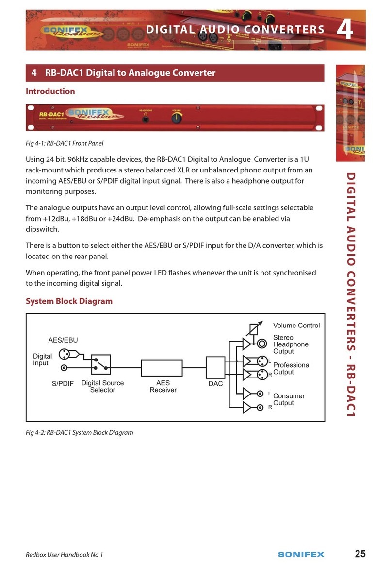
Fig 5-1: RB-DAC1 Front Panel 36
Fig 5-2: RB-DAC1 System Block Diagram 36
Fig 5-3: RB-DAC1 Front Panel 37
Fig 5-4: RB-DAC1 Rear Panel 37
Fig 5-5: RB-DAC1 Full Scale Digits and De-emphasis Settings Switches 38
Fig 6-1: RB-SP1 Front Panel 41

h
Redbox User Handbook No 1
FIGURES
FIGURES
Fig 6-2: RB-SP1 System Block Diagram 41
Fig 6-3: RB-SP1 Front Panel 42
Fig 6-4: RB-SP1 Type and Mode Flow Diagrams 44
Fig 6-5: RB-SP1 Rear Panel 44
Fig 6-6: RB-SP1 Mode Select Dip Switches 45
Fig 7-1: RB-DS2 Front Panel 48
Fig 7-2: RB-DS2 System Block Diagram 50
Fig 7-3: Front Panel CONTROL 50
Fig 7-4: RB-DS2 Rear Panel 51
Fig 7-5: The Default Screen 53
Fig 7-6: The Main Menu 54
Fig 7-7: Maximum Delays in Normal Mode (Using On-Board Memory Only) 67
Fig 7-8: Maximum Delays in Extended FAT Mode with 1 GB Compact
Flash™ Memory Card Installed 68
Fig 7-9: Maximum Delays in Extended RAW Mode with 16 GB Compact Flash™ Memory Card
Installed. 70
Fig 8-1: RB-PD2 Front Panel 71
Fig 8-2: RB-PD2 System Block Diagram 73
Fig 8-3: RB-PD2 Rotary Control Operation 77
Fig 8-4: RB-PD2 Front Panel Buttons 78
Fig 8-5: RB-PD2 Rear Panel 80
Fig 8-6: The Default Screen 82
Fig 8-7: The Main Menu Screen 82
Fig 8-8: The Record Screen 86
Fig 9-1: RB-SD1 Front Panel 101
Fig 9-2: RB-SD1 System Block Diagram 102
Fig 9-3: RB-SD1 Rear Panel 102
Fig 9-4: RB-SD1 Front Panel 105
Fig 10-1: RB-DSD1 Front Panel 111
Fig 10-2: RB-DSD1 System Block Diagram 113
Fig 10-3: RB-DSD1 Front Panel Controls and Indicators 113
Fig 10-4: SILENCE Detect Duration DIPSwitch 115
Fig 10-5: SILENCE Detect Audio Trigger Level DIPSwitch 115
Fig 10-6: SILENCE Detect Stereo/Mono & Sync Source DIPSwitch 115
Fig 10-7: Rear Panel DIPSwitches 116
Fig 10-8: RB-DSD1 Rear Panel 120
Fig 10-9: Serial Port Default Settings 122
Fig 10-10: Indication Page 128
Fig 10-11: Unit Setup Page 129
Fig 10-12: Miscellaneous Page 131
Fig 11-1: XLR Connectors. 136
Fig 11-2: RCA Phono Connector. 136
Fig 11-3: ¼” Jack Connector. 136
Fig 11-4: 25 Way D-Type Connectors. 137
Fig 11-5: 15 Way D-Type Connectors. 137
Fig 11-6: 9 Way D-Type Connectors. 137

Redbox User Handbook No 1
i
Warranty
Warranty and Liability - important the purchaser is advised to read this clause
(a) The Company agrees to repair or (at its discretion) replace Goods which are found to
be defective (fair wear and tear excepted) and which are returned to the Company
within 12 months of the date of despatch provided that each of the following
are satised:
(i) Notication of any defect is given to the Company immediately upon its
becoming apparent to the Purchaser;
(ii) The Goods have only been operated under normal operating conditions and
have only been subject to normal use (and in particular the Goods must have
been correctly connected and must not have been subject to high voltage or
to ionising radiation and must not have been used contrary to the Company’s
technical recommendations);
(iii) The Goods are returned to the Company’s premises at the Purchaser’s expense;
(iv) Any Goods or parts of Goods replaced shall become the property of the
Company;
(v) No work whatsoever (other than normal and proper maintenance) has been
carried out to the Goods or any part of the Goods without the Company’s prior
written consent;
(vi) The defect has not arisen from a design made, furnished or specied by the
Purchaser;
(vii) The Goods have been assembled or incorporated into other goods only in
accordance with any instructions issued by the Company;
(viii) The defect has not arisen from a design modied by the Purchaser;
(ix) The defect has not arisen from an item manufactured by a person other than
the Company. In respect of any item manufactured by a person other than the
Company, the Purchaser shall only be entitled to the benet of any warranty or
guarantee provided by such manufacturer to the Company.
(b) In respect of computer software supplied by the Company the Company does not
warrant that the use of the software will be uninterrupted or error free.
(c) The Company accepts liability:
(i) For death or personal injury to the extent that it results from the negligence of
the Company, its employees (whilst in the course of their employment) or its
agents (in the course of the agency);
WARRANTY
WARRANTY

ii
Redbox User Handbook No 1
(ii) For any breach by the Company of any statutory undertaking as to title, quiet
possession and freedom from encumbrance.
(d) Subject to conditions (a) and (c) from the time of despatch of the Goods from the
Company’s premises the Purchaser shall be responsible for any defect in the Goods
or loss, damage, nuisance or interference whatsoever consequential economic or
otherwise or wastage of material resulting from or caused by or to the Goods. In
particular the Company shall not be liable for any loss of prots or other economic
losses. The Company accordingly excludes all liability for the same.
(e) At the request and expense of the Purchaser the Company will test the Goods to
ascertain performance levels and provide a report of the results of that test. The
report will be accurate at the time of the test, to the best of the belief and Knowledge
of the Company, and the Company accepts no liability in respect of its accuracy
beyond that set out in Condition (a).
(f) Subject to Condition (e) no representation, condition, warranty or other term, express
or implied (by statute or otherwise) is given by the Company that the Goods are of
any particular quality or standard or will enable the Purchaser to attain any particular
performance or result, or will be suitable for any particular purpose or use under
specic conditions or will provide any particular capacity, notwithstanding that the
requirement for such performance, result or capacity or that such particular purpose
or conditions may have been known (or ought to have been known) to the Company,
its employees or agents.
(g) (i) To the extent that the Company is held legally liable to the Purchaser for any
single breach of contract, tort, representation or other act or default, the
Company’s liability for the same shall not exceed the Price of the Goods.
(ii) The restriction of liability in Condition (g)(i) shall not apply to any liability
accepted by the Seller in Condition (c).
(h) Where the Goods are sold under a consumer transaction (as dened by the
Consumer Transactions (Restrictions on Statements) Order 1976) the statutory
rights of the Purchaser are not aected by these Conditions of Sale.
Unpacking the Redbox
The Redbox is shipped with the following equipment. Please check your packaging to
ensure that you have all of the items below. If anything is missing, please contact the
supplier of your equipment immediately.
Item Quantity
Redbox audio interface 1
IEC Mains lead tted with moulded mains plug 1
Handbook and warranty card 1
Fig A: Packing List.
WARRANTY
WARRANTY

Redbox User Handbook No 1
iii
Each Redbox is shipped in protective packaging and should be inspected for damage before
use. Where an item is found to have transit damage, notify the carrier immediately with all
the relevant details of the shipment. Packing materials should be kept for inspection and
also for if the product needs to be returned.
Warranty Registration
In order to register the date of purchase so that we can keep you informed of any design
improvements or modications, it is important to register online at:
www.sonifex.co.uk/register or complete the warranty registration document that is
enclosed and return it to Sonifex Ltd in the UK. For your own records you should write down
the serial number (which can be found on the rear of the Redbox.
Serial Number ………………………………………
Safety Information
Safety of Mains Operated Equipment
This equipment has been designed to meet the safety regulations currently advised
in the country of purchase and it conforms to the safety regulations specied by
use of the CE Mark.
Warning : There are no user serviceable parts inside the equipment. If you should ever
need to look inside the unit, always disconnect the mains supply before removing the
equipment covers.
Voltage Setting Checks
Ensure that the machine operating voltage is correct for your mains power supply by
checking the box in which your Redbox was supplied. The voltage is shown on the box label.
The available voltage settings are 115V, or 230V. Please note that all Redboxes are either
switchable between 115V and 230V, or have a universal power supply.
Fuse Rating
The Redboxes are supplied with a single fuse in the live conducting path of the power
infeed at the power supply. For reasons of safety it is important that the correct rating
and type of fuse is used. Incorrectly rated fuses could present a possible re hazard, under
equipment fault conditions. See the Technical Specications of each product for the fuse
rating. The active fuse is tted on the outside rear panel of the unit.
SAFETY & INSTALLATION
INFORMATION
SAFETY & INSTALLATION INFORMATION

iv
Redbox User Handbook No 1
Power Cable and Connection
An IEC power connector is supplied with the Redbox, which has a moulded plug, attached
– this is a legal requirement. If no moulded plug has been supplied with your Redbox, please
contact your supplier, because an IEC connector is always supplied from the Sonifex factory.
If for any reason, you need to use the Redbox with a dierent power cable, you should use
the following wiring guidelines:
Wire Colour Connection
Green, or green and yellow Earth (E)
Blue, or Black Neutral (N)
Brown, or Red Live (L)
Fig B: Mains Cable Wire Colours
Ordering the Correct Mains Lead
When ordering a Redbox from Sonifex, it is helpful if you can specify your required
operating voltage and mains lead. After the product code add:
UK, for 230V, UK 3 pin to IEC lead
EC, for 230V, European Schuko 2 pin to IEC lead
US, for 115V, 3 pin to IEC lead
AU for 230V, Australasian 3 pin to IEC lead
Fig C: Mains Lead Table.
E.g. order RB-SC1 UK for a UK IEC lead to be supplied.
Installation Information
Atmosphere
The units should be installed in an area that is not subject to excessive temperature
variation (<0°C, >50°C), moisture, dust or vibration.
Electromagnetic Radiation
The cover is connected to earth by means of the xing screws. It is essential to maintain
this earth ground connection to ensure a safe operating environment and provide
electromagnetic shielding.
Fitting Redboxes
Redboxes can be xed to the underside of a mixing desk, or other surfaces using 4.2mm
holes in the sides and xed with 2 x M4 screws or 2 x No. 6 countersink wood screws.
SAFETY & INSTALLATION INFORMATION
SAFETY & INSTALLATION
INFORMATION

Redbox User Handbook No 1
v
They can also be rack-mounted, with either the front, or rear of the Redbox positioned at the
front of the rack:
Front Mounting Redboxes: For rack mounting smaller (28cm) units the optional RB-RK1
(Red) or RB-RK1B (Black) kit can be used (which include 4 o M6 panel xing screws).
Fig D: RB-RK1Small Redbox Front Rack-mount Kit .
Wherever you see this symbol an RB-RK1 front panel rack kit can be used :
Rear Mounting Redboxes: For rear panel mounting you can use either the RB-RK2, or
RB-RK3, depending on the size of your Redbox.
RB-RK2 1U rear panel rack kit for small Redbox range, e.g., RB-BL2
Fig E: RB-RK2 Small Redbox Rear Rack-mount Kit.
e.g. for tting an RB-BL2:
Wherever you see this symbol an RB-RK2 small Redbox rear panel 19”rack kit can be used :
RB-RK3 1U rear panel rack kit for large Redbox range, e.g., RB-DA6
Fig F: RB-RK3 Large Redbox Rear Rack-mount Kit.
e.g. for tting an RB-DA6:
Wherever you see this symbol an RB-RK3 large Redbox rear panel 19”rack kit can be used :
Note: When tting the rear-mounting rack-kits, a notch has been
left on the inside of the right-hand rack-piece for the mains cable to
pass through. Make sure that the mains cable has been put through
the notch before attaching the right hand rack-piece.
SAFETY & INSTALLATION
INFORMATION
SAFETY & INSTALLATION INFORMATION

vi
Redbox User Handbook No 1
Installing the Optional Video Sync Boards in the RB-DSD1
There are 2 optional video sync boards which can be used to synchronise the outputs of the
RB-DSD1 to a 48kHz sample rate from an analogue or digital video signal:
RB-SYA - The Analogue video sync board will accept a composite signal of NTSC (525), PAL
(625) & SECAM (625) signals covered by SMPTE-170-M (NTSC) and ITU-R BT.470-6 (PAL &
SECAM).
RB-SYD - The Digital video sync board will accept 270Mbps SD-SDI and HD-SDI signals
covered by SMPTE-259-M-C (SD) and SMPTE-292M (HD).
Opening the RB-DSD1
Warning: The power must be switched o at the supply or the power lead must be
disconnected before attempting to open the unit. Removal of the cover can expose
dangerous voltages.
1. Remove the 4 screws in the corners of the rear panel.
2. Remove the 4 screws on the top and bottom panels which hold the rear panel in place (2
on the top and 2 on the bottom).
3. Remove the screw in the centre of the front panel.
4. Slide the rear panel and main PCB backwards out of the metal chassis giving you
internal access.
5. Remove the rubber grommet/bung on the rear panel which covers the hole for the video
sync connector.
6. Remove the 2 screws from the bottom of the sync card pillars and, making sure to keep
the plastic washers in place at the bottom of the pillars, t the 20 way pin header into the 20
way connector on the RB-DSD1 motherboard.
7. Underneath the board, insert the 2 screws to x the board in place.
To put the unit back together, slide the PCB back into the chassis and ret the screws in
reverse order.
The video synchronisation is chosen using the front panel DIPSwitches (see page 6).
Follow these instructions to t either of the sync boards.
SAFETY & INSTALLATION INFORMATION
SAFETY & INSTALLATION
INFORMATION

Redbox User Handbook No 1
vii
Reset
Sync Card
Pillar Mount
Power
Plug
Fuse
Case
Remote
Connector
Dipswitches
Sync Card
Pillar Mount
Word Clock
AES/EBU
Sync
Input
Fig G: RB-DSD1 Optional Video Sync Installation
SAFETY & INSTALLATION
INFORMATION
SAFETY & INSTALLATION INFORMATION

viii
Redbox User Handbook No 1
WEEE & RoHS Directives - Sonifex Statement
The Waste Electrical and Electronic Equipment (WEEE) Directive was agreed on
13 February 2003, along with the related Directive 2002/95/EC on Restrictions
of the use of certain Hazardous Substances in electrical and electronic
equipment (RoHS).
The Waste Electrical and Electronic Equipment Directive (WEEE) aims to minimise the
impacts of electrical and electronic equipment on the environment during their life times
and when they become waste. It applies to a huge spectrum of products. It encourages
and sets criteria for the collection, treatment, recycling and recovery of waste electrical and
electronic equipment. All products manufactured by Sonifex Ltd have the WEEE directive
label placed on the case. It gives a contact for individuals who are unsure about the correct
procedure when the product has reached its “end of use”.
Sonifex Ltd will be happy to give you information about local organisations that can
reprocess the products, or alternatively all products that have reached “end of use” can be
returned to Sonifex and will be reprocessed correctly free of charge.
Sonifex Ltd has phased out the use of certain hazardous substances identied in the
European Union’s Restriction of Hazardous Substances (RoHS) directive. The RoHS directive
limits the use of certain hazardous substances currently used in EEE manufacture, including
lead, mercury, cadmium, hexavalent chromium, and halide-containing compounds PBB
(polybrominated biphenyl) and PBDE (polybrominated diphenyl ether). Elimination of these
substances will result in more environmentally friendly recycling of electronic equipment.
For the products which Sonifex manufacture, the main area where products were aected
was in the use of lead for manufacturing and assembling electronics circuit boards.
Sonifex Ltd practices lead-free (LF) manufacturing processes. LF solder is used on the
surface-mount PCB manufacturing processes and for hand soldering. The printed circuit
boards (PCBs) used are either gold plated, or immersion tin plated, both of which use no
lead. Historically the PCBs were hot air solder levelled (HASL) PCBs which used tin/lead
based solder.
The manufacturing processes include the assembly of purchased components from various
sources. Product is oered as RoHS compliant, or LF, only after sucient evidence is received
from the component manufacturers that their components are RoHS compliant. Sonifex
Ltd relies solely on the distributor, or manufacturer, of the components for identication of
RoHS compliance. Thus whilst every eort is made to ensure compliance, Sonifex Ltd makes
no warranty, or certication, or declaration of compliance concerning said components.
Sonifex Ltd denes“Lead Free” as pertaining to any product, which has been manufactured
by Sonifex Ltd using components which have been declared by the manufacturers as
“Lead Free”. All statements by Sonifex Ltd of RoHS compliance are based on component
manufacturer documentation.
SAFETY & INSTALLATION INFORMATION
SAFETY & INSTALLATION
INFORMATION

Redbox User Handbook No 1
1
DIGITAL AUDIO CONVERTERS - RB-ADDA
DIGITAL AUDIO CONVERTERS
1 RB-ADDA Combined A/D and D/A Converter
Introduction
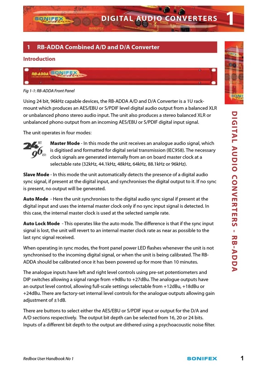
Fig 1-1: RB-ADDA Front Panel
Using 24 bit, 96kHz capable devices, the RB-ADDA A/D and D/A Converter is a 1U rack-
mount which produces an AES/EBU or S/PDIF level digital audio output from a balanced XLR
or unbalanced phono stereo audio input. The unit also produces a stereo balanced XLR or
unbalanced phono output from an incoming AES/EBU or S/PDIF digital input signal.
The unit operates in four modes:
Master Mode - In this mode the unit receives an analogue audio signal, which
is digitised and formatted for digital serial transmission (IEC958). The necessary
clock signals are generated internally from an on board master clock at a
selectable rate (32kHz, 44.1kHz, 48kHz, 64kHz, 88.1kHz or 96kHz).
Slave Mode - In this mode the unit automatically detects the presence of a digital audio
sync signal, if present at the digital input, and synchronises the digital output to it. If no sync
is present, no output will be generated.
Auto Mode - Here the unit synchronises to the digital audio sync signal if present at the
digital input and uses the internal master clock only if no sync input signal is detected. In
this case, the internal master clock is used at the selected sample rate.
Auto Lock Mode - This operates like the auto mode. The dierence is that if the sync input
signal is lost, the unit will revert to an internal master clock rate as near as possible to the
last sync signal received.
When operating in sync modes, the front panel power LED ashes whenever the unit is not
synchronised to the incoming digital signal, or when the unit is being calibrated. The RB-
ADDA should be calibrated once it has been powered up for more than 10 minutes.
The analogue inputs have left and right level controls using pre-set potentiometers and
DIP switches allowing a signal range from +9dBu to +27dBu. The analogue outputs have
an output level control, allowing full-scale settings selectable from +12dBu, +18dBu or
+24dBu. There are factory-set internal level controls for the analogue outputs allowing gain
adjustment of ±1dB.
There are buttons to select either the AES/EBU or S/PDIF input or output for the D/A and
A/D sections respectively. The output bit depth can be selected from 16, 20 or 24 bits.
Inputs of a dierent bit depth to the output are dithered using a psychoacoustic noise lter.
1

2
Redbox User Handbook No 1
For the digital output, there is a switch available to dene the content of the channel status
bits embedded within the digital audio stream. The channel status bits can be set to either
Professional or Consumer Mode.
System Block Diagram
Fig 1-2: RB-ADDA System Block Diagram
Front Panel Indicators
The LED on the front panel is normally red to indicate that power is present on the unit.
However, it also has a secondary role to indicate the status of the digital inputs
Fast ashing between red and amber – indicates a loss of digital input signal or that the unit
is being calibrated.
Rear Panel Connections and Operation
Fig 1-3: RB-ADDA Rear Panel
DIGITAL AUDIO CONVERTERS - RB-ADDA
DIGITAL AUDIO CONVERTERS
XLR Analogue
Inputs
XLR Analogue
Outputs
AES/EBU
Output
Status Select
Switches
AES/EBU
Input
RCA Phono
Inputs
RCA Phono
Outputs
S/PDIF
Input &
Output
Frequency & Synch
Mode Rotary Switch
Digital Select
Button
Digital Select
Button
1

Redbox User Handbook No 1
3
RB-ADDA Inputs
XLR Analogue Inputs (Left and Right)
The XLR 3 pin sockets used for the left and right channel inputs are electronically balanced
and have an impedance of greater than 10kΩ bridging. Each XLR has the following
connections:
Pin 1: Screen.
Pin 2: Phase.
Pin 3: Non-phase.
RCA Phono Inputs (Left and Right)
The two left and right RCA inputs are unbalanced and have an impedance of greater
than 20kΩ.
Input Level Adjustment
The input gain can be individually adjusted for left and right channels by dipswitches and
through pre-set potentiometers accessible on the rear panel. For full scale dB settings refer
to Fig 1-4.
Individual preset pots give a further ± 3dBu to give a total gain range of +9dBu to +27dBu
for full-scale digits. The consumer input on the phono connector has a further 10dbU gain
incorporated to give a total gain range of -1dBu to +17dBu for full-scale digits.
AES/EBU Inputs
The digital input XLR 3 pin socket has an impedance of 110 Ω. It has the following
connections:
Pin 1: Screen
Pin 2: Phase
Pin 3: Non-phase
The signals on this connector should meet the IEC 60968 specication
S/PDIF Inputs
The S/PDIF digital phono inputs have an impedance of 75Ω.
RB-ADDA Outputs
Analogue Outputs (Left and Right)
The XLR 3 pin output plug connectors are electronically balanced with an output
impedance of less than 50Ω. They have the following connections:
Pin 1: Screen.
Pin 2: Phase.
Pin 3: Non-phase.
RCA Phono Outputs (Left and Right)
These RCA (phono) outputs are unbalanced and have an output impedance of less
than 75Ω.
DIGITAL AUDIO CONVERTERS - RB-ADDA
DIGITAL AUDIO CONVERTERS 1

4
Redbox User Handbook No 1
Output Level Adjustment
The output gain can be individually adjusted for left and right channels through the rear
panel by dipswitches. Each output gain can be set for a signal of full-scale digits in the
digital domain to give +12, +18 or +24dBu output on the XLR connectors (see Fig 1-4).
The consumer output on the phono connector has a further 10dbU attenuation
incorporated.
AES/EBU Output
The digital output XLR 3 pin socket has an impedance of 110Ω. It has the following
connections:
Pin 1: Screen
Pin 2: Phase
Pin 3: Non-phase
The signals on this connector will comply with the IEC 60968 specication
S/PDIF Output
The digital output S/PDIF phono output has an impedance of 75Ω.
Rear Panel Controls
Full Scale dB Settings
The full-scale dB settings can be set for signals of +12, +18, +24 dBu to give full-scale digits
in the digital domain.
Analogue (A/D)
Input Full Scale
Setting (dBu)
Switch 1 Switch 2
+12 OFF OFF
+18 ON OFF
+24 ON ON
Analogue (D/A)
Output Full Scale
Setting (dBu)
Switch 3 Switch 4
+12 OFF OFF
+18 ON OFF
+24 ON ON
Fig 1-4: RB-ADDA Full Scale dB Settings
DIGITAL AUDIO CONVERTERS - RB-ADDA
DIGITAL AUDIO CONVERTERS
1
Other manuals for Redbox RB Series
1
This manual suits for next models
11
Table of contents
Other Sonifex Media Converter manuals

Sonifex
Sonifex Redbox RB-DEED8 Instruction Manual

Sonifex
Sonifex Redbox Series Instruction Manual

Sonifex
Sonifex Redbox RB-SC2 Instruction Manual

Sonifex
Sonifex avn AVN-DIO20 User manual

Sonifex
Sonifex Dante AVN-DIO19 User manual
Sonifex
Sonifex Redbox RB-ADDA2 Instruction Manual

Sonifex
Sonifex Redbox RB-VHEDD8 Instruction Manual

Sonifex
Sonifex AVN-DIO14 User manual
Sonifex
Sonifex Redbox RB-VHDMA8 Instruction Manual
Sonifex
Sonifex CM-ULR1 User manual