Sonnen sonnenBatterie eco 8.2 User manual
info@sonnenbatterie.de · www.sonnenbatterie.de
Operating instructions |
for operators
KD-225 · Part no. 52186 · Version X04
sonnenBatterie eco 8.2

EN IMPORTANT
► Read this documentation carefully before operation.
► Retain this document for reference purposes.
Publisher
sonnen GmbH
Am Riedbach 1
87499 Wildpoldsried
Service number +49 8304 9 933 444
E-Mail i[email protected]
Document
Document number KD- 5
Part number 5 186
Version X04
Valid for UK, IE, AU
Publication date 4/04/ 017
/ 6
KD- 5 | Part no. 5 186 | EN | X04

Table of contents
Table of contents
1 Information about this document.................................................................
1.1 Target group of this document.............................................................................5
1. Designations in this document............................................................................5
1.3 Explanation of symbols........................................................................................5
2 Safety..............................................................................................................6
.1 Intended Use......................................................................................................... 6
. Requirements for the electrician.......................................................................6
.3 General safety information.................................................................................6
.3.1 Danger due to incorrect operation............................................................6
.3. Danger to life due to explosive and flammable materials........................7
.3.3 Danger to life due to product modifications or changes to the product
environment.......................................................................................................... 7
.3.4 Danger of injury and risk of material damage due to improper repairs. 7
.3.5 Conduct in case of a fire / Important information for fire services.......7
.4 Regulations (directives, laws, standards)...........................................................8
.5 Warnings............................................................................................................... 8
3 Product description.....................................................................................10
3.1 Technical data...................................................................................................... 10
3. Type plate............................................................................................................. 11
3.3 Symbols on the outside of the storage system................................................1
3.4 Functional description.......................................................................................13
3.4.1 Basic principle............................................................................................ 13
4 Commissioning.............................................................................................14
4.1.1 Removing the cover....................................................................................14
4.1. Switching on the storage system..............................................................14
Internet portal..............................................................................................1
5.1 Logging into the internet portal.........................................................................15
5. Using the overview page....................................................................................15
5.3 Using the status page......................................................................................... 16
5.4 Using the control page.......................................................................................17
5.5 Using the history page.......................................................................................18
5.5.1 Elements of the power graph....................................................................18
5.5. Analysis of power diagram........................................................................19
5.5.3 Analysing pie charts................................................................................. 0
5.6 Using the forecast page..................................................................................... 1
6 Maintenance.................................................................................................22
KD- 5 | Part no. 5 186 | EN | X04 3 / 6

Table of contents
6.1 Checking function..............................................................................................
6. Cleaning.............................................................................................................
7 Troubleshooting...........................................................................................23
8 Decommissioning........................................................................................24
9 Uninstallation and disposal.........................................................................2
9.1 Uninstallation...................................................................................................... 5
9. Disposal.............................................................................................................. 5
10 Annex..........................................................................................................26
10.1 EU-declaration of conformity........................................................................ 6
10. Warranty for UK and Ireland.......................................................................... 6
10.3 Warranty for Australia.................................................................................... 6
10.4 Safety data sheet............................................................................................ 6
4 / 6 KD- 5 | Part no. 5 186 | EN | X04
Information about this document
1
1 Information about this document
This document describes the operation of the sonnenBatterie eco 8. .
Observe the following points:
► Read this document in its entirety before beginning operation.
► Keep this document in the vicinity of the sonnenBatterie.
1.1 Target group of this document
This document is intended for the storage system operator.
1.2 Designations in this document
The following designations are used in this document:
Complete designation Designation in this document
sonnenBatterie eco 8. storage system
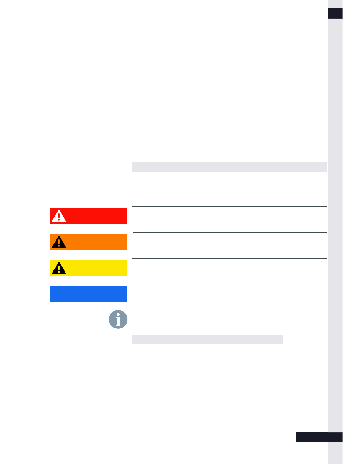
1.3 Explanation of symbols
Extremely dangerous situation leading to certain death or serious injury if the
safety information is not observed.
Dangerous situation leading to potential death or serious injury if the safety
information is not observed.
Dangerous situation leading to potential injury if the safety information is not
observed.
Indicates actions that may cause material damage.
Important information not associated with any risks to people or property.
Symbol Meaning
► Work step
1. . 3. … Work steps in a defined order
•List
Table 1: Additional symbols
KD- 5 | Part no. 5 186 | EN | X04 5 / 6
CAUTION
DANGER
WARNING
Notice
CAUTION
DANGER
WARNING
Notice
CAUTION
DANGER
WARNING
Notice
CAUTION
DANGER
WARNING
Notice
Other manuals for sonnenBatterie eco 8.2
4
This manual suits for next models
8
Table of contents
Other Sonnen Camera Accessories manuals


Popular Camera Accessories manuals by other brands


Trojan
Trojan GC2 48V quick start guide

Calumet
Calumet 7100 Series CK7114 operating instructions

Ropox
Ropox 4Single Series User manual and installation instructions

Cambo
Cambo Wide DS Digital Series Main operating instructions

Samsung
Samsung SHG-120 Specification sheet

Ryobi
Ryobi BPL-1820 Owner's operating manual