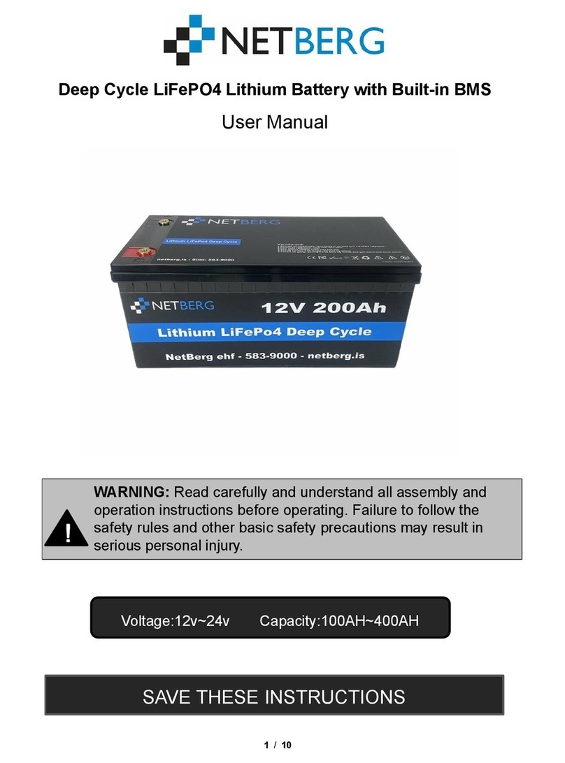
Sonnen Batterie Evo User manual

Installation Guide
Page 1of 53
Installation manual | for authorised electricians
sonnenBatterie Evo
info@sonnen.com.au

Installation Guide
Page 2of 53
IMPORTANT
Read this document carefully before installation / operation.
Retain this document for reference purposes.
Publisher
sonnen Australia Pty Ltd
Tenancy 6, Lionsgate Business Park, 180 Phillip Highway
Elizabeth South SA 5112, Australia
Service number +61 137 666
Email [email protected]
Document
Document number 5000580
Version 000
Valid for AU, NZ
Publication date 10/03/2022

Installation Guide
Page 3of 53
Table of Contents
1Information about this document....................................................................................6
1.1 Target group of this document..................................................................................................6
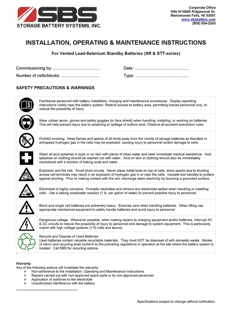
1.2 Designations in this document............................................................................................... 6
1.3 Symbols in this document ....................................................................................................... 7
2Safety..................................................................................................................................... 8
2.1 Intended use ................................................................................................................................8
2.2 Requirement for the electrician............................................................................................8
2.3 Important safety instructions................................................................................................. 9
2.4 Voltage inside the storage system........................................................................................ 9
2.5 Prohibited uses.......................................................................................................................... 10
2.6 Handling the battery modules.............................................................................................. 10
2.7 Conduct in case of a fire.........................................................................................................12
3Product description........................................................................................................... 13
3.1 Technical data ............................................................................................................................13
3.2 System components.................................................................................................................15
3.3 Symbols on the storage system............................................................................................16
4Storage and transport....................................................................................................... 17
4.1 Storage .........................................................................................................................................17
4.1.1 Ambient conditions during storage.................................................................................17
4.1.2 Storing the battery modules .........................................................................................17
4.2 Transport..................................................................................................................................... 18
4.2.1 Transporting battery modules ..................................................................................... 18
4.2.2 Inspecting for transport damage................................................................................ 18
4.2.3 Transport to the installation location .........................................................................19
4.2.4 Temperature adjustment after transport..................................................................19
5Scope of delivery ............................................................................................................... 21
6Mounting and electrical installation ............................................................................. 22

Installation Guide
Page 4of 53
6.1 Mounting.....................................................................................................................................23
6.1.1 Selecting the installation location...................................................................................23
6.1.2 Observing minimum clearances..................................................................................23
6.1.3 Inspecting the storage system ....................................................................................23
6.1.4 Installing the main cabinet ........................................................................................... 24
6.1.5 Running external wiring into the enclosure.............................................................27
6.1.6 Secure enclosure to location...................................................................................... 28
6.2 Installing electrical and data connections ....................................................................... 28
6.2.1 Connecting grid and essential load wiring.............................................................. 28
6.2.2 Connecting ethernet and modbus.............................................................................29
6.3 Installing the battery modules............................................................................................. 30
6.3.1 Overview sonnenModule 4 ......................................................................................... 30
6.3.2 Installing the battery modules .................................................................................... 30
6.3.3 Connecting power and BMS to the battery modules ..........................................33
6.4 Installing the power meter ....................................................................................................35
6.4.1 Components overview...................................................................................................35
6.4.2 Overview measurement methods............................................................................. 36
6.4.3 Connecting the power meter......................................................................................37
6.4.4 Configuring the power meter.....................................................................................40
7Operation of the system.................................................................................................43
7.1 Startup procedure .................................................................................................................. 43
7.2 Shutdown procedure ............................................................................................................. 43
7.3 LED indicator............................................................................................................................44
7.4 Commissioning.........................................................................................................................44
7.4.1 Taking photos to document installation ..................................................................44
7.4.2 Filling in the commissioning report...........................................................................44
7.5 Commissioning Assistant 2.0 .............................................................................................. 45
7.5.1 Establishing connection to the storage system.................................................... 45
7.5.2 Running the commissioning assistant ...................................................................... 45

Installation Guide
Page 5of 53
7.5.3 Multiple system operation ........................................................................................... 49
8Maintenance.......................................................................................................................50
9Troubleshooting ................................................................................................................50
10 Uninstallation & Disposal................................................................................................. 52
10.1 Uninstallation.............................................................................................................................52
10.2 Disposal .......................................................................................................................................52

Installation Guide
Page 6of 53
1Information about this document
This document describes the installation of the sonnenBatterie Evo storage system.
Read this document in its entirety.
Keep this document in the vicinity of the storage system.
1.1 Target group of this document
This document is intended for authorised and certified electricians. The actions described
here must only be performed by authorised and certified electricians. Definition and the
criteria of authorised and certified electricians can be found in section 2.2.
1.2 Designations in this document
The following designations are used in this document:
Complete designation
Designation in this document
sonnenBatterie Evo
Storage system

Installation Guide
Page 7of 53
1.3 Symbols in this document
Extremely dangerous situation leading to certain death or
serious injury if the safety information is not observed.
Dangerous situation leading to potential injury if the safety
information is not observed.
Indicates actions that may cause material damage.
Important information not associated with any risks to people
or property.
Symbol
Meaning
Work step
1.2.3. …
Work steps in a defined order
Condition
-
List
Table 1: Additional symbols
Dangerous situation leading to potential death or serious
injury if the safety information is not observed.

Installation Guide
Page 8of 53
2Safety
2.1 Intended use
The sonnenBatterie Evo is a battery storage system which can be used to store electrical
energy. Improper use of this system poses a risk of death or injury to the user or third
parties as well as damage to the product and other items of value. The following points
must therefore be observed in order to comply with the intended use of the product:
-The storage system must not be installed in any kind of combination.
-The storage system must be fully installed in accordance with the installation
instructions.
-The storage system must be installed by a licensed electrician who has completed
the sonnen installer accreditation training. Country-specific regulations
concerning electrical installations must be observed at all times.
-The storage system must only be used at a suitable installation location.
-The transport and storage conditions must be observed.
The following uses are not permissible:
-Operation in flammable environments or areas at risk of explosion.
-Operation in locations at risk of flooding.
-Operation in an outdoor location whereby the supplied IP rating of the enclosure
has not remained intact.
-Operation of the battery modules outside of its storage system.
Failure to comply with the conditions of the warranty and the
information specified in this document invalidates any
warranty claims.
2.2 Requirement for the electrician
Improper installation can result in personal injury and/or damage to components. For this
reason, the storage system must only be installed and commissioned by authorised and
sonnen certified electricians.
Authorised and sonnen certified electricians must meet the following criteria:

Installation Guide
Page 9of 53
-The electrician must be a person with a technical knowledge or sufficient
experience to enable him/her to avoid dangers which electricity may create.
-The electrician must have successfully completed the sonnen Australia installer
training and have valid sonnen installer accreditation at the time of installation.
2.3 Important safety instructions
-Only use the storage system in its original state.
-Do not modify the storage system.
-Do not use a damaged storage system.
-Ensure all safety devices are in perfect working condition.
-Safety devices must never be overridden, blocked or tampered with.
-The interfaces of the storage system must be wired in accordance with the
product documentation.
-An appropriate and readily accessible disconnect device shall be incorporated in
the fixed wiring.
-All repairs on the storage system must be performed by authorised service
technicians only.
-The replacement of battery modules must be performed by authorised service
technicians only. When replacing batteries, replace with the same type and
number of batteries or battery modules.
2.4 Voltage inside the storage system
The storage system contains live electrical parts, which poses a risk of
electrical shock. The storage system inverter also contains capacitors
which carry voltage even after the storage system is switched off.
Therefore:
Switch off the storage system to electrically isolate it before carrying
out any work (see Switching the storage system off to electrically
isolate it (see section 7.2).
Only then can the storage system be opened.

Installation Guide
Page 10 of 53
Even if the utility grid fails, the storage system will continue delivering
power. Before servicing the storage system:
Turn off the storage system.
Danger to life due to electric shock.
2.5 Prohibited uses
Do not use the storage system:
-In vehicles
-In standing water or (>90%) humidity locations
-In areas at risk of filling with combustible dust (flour dust, sawdust, etc.)
-In direct sunlight
-In locations with the air ammonia content exceeds 20 ppm
-In presence of corrosive gases
-In locations with elevations above 2,000 meters above sea-level
-In locations with ambient temperature outside -10°C - 50°C
2.6 Handling the battery modules
Figure 1: sonnenModule4 battery module
-The battery modules have a nominal voltage of 102.4 VDC and therefore fall into
the range of protected extra-low voltage (under 120 VDC).
-The battery modules are utilising high-performance Lithium-Iron-Phosphate (LFP)
-The battery modules contain no metallic Lithium.

Installation Guide
Page 11 of 53
WARNING – RISK OF ELECTRIC SHOCK
Residual voltage is always present on DC terminals, and the battery
modules cannot be turned off.
Avoid contact with terminals.
When working on the storage system:
-Take off metallic jewellery.
-Turn off the storage system.
-Use insulated tools.
-Wear personal protective equipment, including safety glasses, insulated
gloves, and safety shoes.
The battery modules installed in the storage system are protected by
multiple protective devices and can be operated safely. Despite their
careful design, the battery cells inside the battery modules may corrode or
experience thermal runaway in the event of mechanical damage, heat or a
fault.
This can have the following effects:
-High heat generation on the surface of the battery cells.
-Electrolyte may escape.
-The escaping electrolyte may ignite and cause an explosive flame.
-The smoke from burning battery modules can irritate the skin, eyes and
throat.
Therefore, proceed as follows:
Do not open the battery modules.
Do not mechanically damage the battery modules (pierce, deform,
strip down, etc.)
Do not modify the battery modules.
Do not allow the battery modules to come into contact with water
(except when extinguishing a fire in the storage system).
Do not heat the battery modules. Operate them only within the
permissible temperature range.
Keep the battery modules well away from sources of ignition.
Do not short-circuit the battery modules. Do not allow them to come
into contact with metal.

Installation Guide
Page 12 of 53
Do not continue to use the battery modules after a short circuit.
Do not deep-discharge the battery modules.
In the event that module contents are released:
Do not enter the room under any circumstance.
Avoid contact with the escaping electrolyte.
Contact the fire services.
2.7 Conduct in case of a fire
Fire may occur with electrical equipment despite its careful design. Likewise, a fire in the
vicinity of the equipment can cause the storage system to catch fire, releasing the
contents of the battery modules.
In the event of a fire in the vicinity of the product or in the storage system itself, proceed
as follows:
Only firefighters with appropriate protective equipment (safety gloves, safety
clothing, face guard, breathing protection) are permitted to enter the room
where the burning storage system is located.
There is a danger of electrocution when extinguishing fire while the storage system is
switched on. Therefore, before starting to extinguish the fire:
Switch off the storage system to electrically isolate it.
Switch off the main switch in the building.
If the storage system and/or main switch cannot be safely switched off:
Observe the minimum distances specified for the extinguishing agent used. The
storage system works with an output voltage of 230 V (AC) and is therefore
considered a low-voltage system.
-A storage system fire can be extinguished using conventional extinguishing
agents.
-Water is recommended as an extinguishing agent in order to cool the battery
modules and therefore, prevent thermal runaway in battery modules which are
still intact.

Installation Guide
Page 13 of 53
3Product description
3.1 Technical data
sonnenBatterie Evo
System specifications (AC)
Nominal voltage
230 V
Nominal frequency 50 Hz
Nominal power rating (@ 40 ⁰C)
5000 W
Rated current
22 A
Rated active power
5000 W
Rated apparent power
5000 VA
Max. current (continuous) 22 A
Charge/ discharge power
5000 W
Power factor range
0.5 leading … 0.5 lagging
Short circuit current 454A @ 12.13ms
Mains connection
Single-phase, L / N / PE
Mains topology
TN / TT
Grid integration
AC coupled
Inverter topology
Transformerless
Active anti-islanding method
Integrated
Battery specifications (DC)
Nominal voltage
102.4 VDC
Battery voltage range
160…230 VDC
Operating voltage
204.8 VDC
No. of battery modules 2
Nominal capacity
11 kWh
Usable capacity (@ 90% DoD)
10 kWh
Max charge/ discharge current (continuous)
40 A
Max charge/ discharge power
5000 W
Short circuit current
2880 A
Cell chemistry
Lithium Iron Phosphate
(LiFePO4)
Over-current protection
Fuse protection
General data
Dimensions in mm (W x H x D)
710mm x 1400mm x 427mm
Weight (approximate)
165 kg
Ambient temperature range
-5 ⁰C to 45 ⁰C
5 ⁰C to 35 ⁰C (Max power)
Total harmonic distortion
<5%
Inverter efficiency
94.4% peak
On-grid pass-through
35 A
Applications
Time-of-use
Self-consumption
Backup
System cooling
Forced-air cooling
Communication Ethernet
Warranty
10 years or 10,000 cycles

Installation Guide
Page 14 of 53
Safety
Protection class
I / PE conductor
Overvoltage category
III
Degree of protection
IP 56
Rated short-withstand current (ICW)
1.5 kA
Ambient conditions
Environment
Outdoor
Storage temperature range
0 °C ... 40 °C
Transport temperature range -15 °C ... 50 °C
Max. rel. humidity
90 %, non-condensing
Permissible installation altitude
2,000 m above sea level
Pollution degree 3
Backup specification
Nominal backup current (Continuous) 22 A
Nominal output voltage
230 V
Nominal power
5000 W
Nominal frequency
50 Hz
Max backup power (Max 30mins)
5300 VA
Max backup power (Max 60s)
7050 VA
Max backup power (Max 300ms)
7600 VA
Maximum compatible PV inverter
6 kW
Certifications
Grid connections AS/NZS 4777.2:2020
EMC / EMI protection
EN 61000-6-1, EN 61000-6-3,
IEC 62040-2
Safety
IEC 62040-1, IEC 62477-1, IEC
62619, IEC 62109-1, IEC 62109-2
Additional ambient conditions:
-The installation location must not be at risk of flooding.
-Installation room should be ventilated.
-All applicable building codes must be observed.
-Even floor, suitable for heavy loads.
-Observe fire control standards.
-Free from corrosive and explosive gases (ammonia content max. 20 ppm).
-Free from dust (especially flour dust or sawdust).
-Free from vibrations.
-Free access to the installation location.
-If possible, no direct sunlight.

Installation Guide
Page 15 of 53
3.2 System components
Figure 2: Overview system components
Item Description Function
1
Power Unit
Contains the inverter and the control unit
2
Battery Module
Stores energy
3
Base
Contains the air filter
4
Legs
Provide elevation and compensation for uneven grounds
5
Power Button
System startup and shutdown
6
Black Start Button
System startup in offgrid condition
7
LED Indicator
Indication of the state of operation

Installation Guide
Page 16 of 53
3.3 Symbols on the storage system
Symbol
Description
Warning: flammable materials.
Warning: hazards due to batteries.
Warning: electrical voltage.
Warning: electrical voltage. Wait five minutes after switching off
(capacitors de-energising time).
Warning: equipment with multiple sources of supply (PV generator,
AC mains and battery).
Warning: product is heavy.
CE mark. The product meets the requirements of the applicable EU
directives.
RCM Mark for Australia and New Zealand.
WEEE mark. The product must not be disposed of in household
waste; dispose of it through environmentally friendly collection
centres.
Observe the documentation. The documentation contains safety
information.

Installation Guide
Page 17 of 53
4Storage and transport
4.1 Storage
Storage describes the condition when the storage system is not connected to the public
electrical mains and the battery modules cannot be automatically charged.
4.1.1 Ambient conditions during storage
While not in use, the system and battery modules must be stored under the following
conditions:
-Ambient storage temperature of battery modules (<6 months) 0 °C – 40 °C
-Ambient storage temperature of Inverter 0 °C – 40 °C
-Humidity max. 90% (non-condensing)
-Properly ventilated
-Maximum elevation of 2,000 meters above sea level
-Fire safety regulations observed
-Free of dust
-Free of corrosive and explosive gases
-Free of vibrations
-Plain surface that can bear heavy weights
-Location meets local building codes
4.1.2 Storing the battery modules
Deep-discharge of the battery modules
Damage to the battery modules!
Do not disconnect the storage system from the public grid
for long periods of time.
Never continue to operate battery modules which have been
deep-discharged.
During storage, the battery modules automatically discharge at a minimal level. Deep-
discharge could damage or destroy the battery modules. For this reason, the battery
modules can only be stored for a limited amount of time.
Observe the following points:
-The battery modules must be charged to at least 30%before storing them.

Installation Guide
Page 18 of 53
-Store the battery modules for no longer than 6 months.
-After six months, battery modules require charging. Contact service for guidance.
4.2 Transport
Lithium-ion battery modules are hazardous materials. Therefore, the following points
must be observed when transporting the battery modules:
Observe the general transport regulations based on the mode of transport as well
as all legal regulations.
-Transportation temperature range (<3 months) -20°C - 60°C
Consult an external expert for hazardous materials.
The following data is relevant for transport:
-Hazardous material: Class 9
-UN number: UN3480 “lithium-ion battery modules”
-Weight of a battery module: 40 kg
4.2.1 Transporting battery modules
Improper transport of battery modules
Fire outbreak at battery modules or emission of toxic
substances!
Transport the battery modules in their original packaging
only. If you no longer have the original packaging, new
packaging can be requested from sonnen Australia.
Never transport damaged battery modules.
4.2.2 Inspecting for transport damage
Use of damaged battery modules
Fire outbreak at battery modules or emission of toxic
substances!
Unpack the battery modules immediately after transport and
inspect them for transport damage.
Do not use the battery modules under any circumstance.
Notify the service team.

Installation Guide
Page 19 of 53
Insulation fault when storage system is damaged
Danger of electric shock when touching damaged insulation
elements!
Unpack the storage system immediately after transport and
inspect it for transport damage.
Do not use a damaged storage system under any
circumstance.
4.2.3 Transport to the installation location
4.2.4 Temperature adjustment after transport
Forming of condensation
Damage to the storage system!
Check the inside of the storage system for condensation
before installation.
Only install the storage system if there is no condensation on
the surfaces.
If the temperature of the storage system is lower than the ambient temperature of the
room when it is delivered, condensation may form inside the storage system.
If the storage system has been transported in sub-zero temperatures, proceed as
follows:
1. Set up the storage system in a suitable location.
High weight of the storage system
Risk of injury by lifting/dropping the storage system!
Wear safety footwear when setting up.
Ensure a secure footing.
At least two people are necessary to carry the main cabinet
of the storage system.

Installation Guide
Page 20 of 53
2. Open all main cabinet doors.
3. Leave the storage system to stand for at least 24 hours with open main cabinet
doors.
4. Only then can you commission the storage system.
Table of contents
Other Sonnen Camera Accessories manuals
