Sonnen sonnenBatterie eco User manual


This manual refers to:
Hardware version: 1.1
Software version: 5.00 (370)
Latest revision: 08/05/16
If you need help or service, contact the company that commissioned your
storage system. You can find the contact address on the inside of the door
of the storage system or on the commissioning protocol.


Contents
About this manual ............................................................................................................. 1
Target audience.............................................................................................................................1
Symbols used .................................................................................................................................1
Safety ................................................................................................................................2
Intended use ................................................................................................................................2
Prohibited uses.............................................................................................................................2
General safety instructions ........................................................................................................3
General warnings ........................................................................................................................3
Description and Specifications ......................................................................................... 4
Dimensions ...................................................................................................................................9
Description of use...................................................................................................................... 10
Modes of operation ................................................................................................................... 11
Turning the system on and off ......................................................................................... 13
Turning the storage system on..................................................................................................13
Shutting the storage system down.......................................................................................... 14
User interface................................................................................................................... 15
Maintenance and care ......................................................................................................23
Function control .......................................................................................................................23
Care of the storage system......................................................................................................23
Nameplate ....................................................................................................................... 25
Sequence of operations................................................................................................... 26
Glossary........................................................................................................................... 28
Fire-related instructions ................................................................................................. 29

Tables and figures
Description and Specifications
Fig. 1 Energy flow .............................................................................................................................................................................10
Fig. 2 Self-consumption mode........................................................................................................................................................11
Fig. 3 Backup mode ......................................................................................................................................................................... 12
Turning the system on and off
Fig. 4 Switch and circuit breaker ................................................................................................................................................... 13
Fig. 5 Circuit breaker.......................................................................................................................................................................14
User interface
Fig. 6 Touchscreen menu screen ................................................................................................................................................... 15
Fig. 7 Touchscreen function screen............................................................................................................................................... 15
Fig. 8 Touchscreen switch load screen .........................................................................................................................................16
Fig. 9 Touchscreen behavior screen .............................................................................................................................................. 17
Fig. 10 Touchscreen Behavior tab ................................................................................................................................................. 17
Fig. 11 Touchscreen charge behavior screen ................................................................................................................................18
Fig. 12 Touchscreen offgrid tab......................................................................................................................................................18
Fig. 13 Touchscreen producer screen............................................................................................................................................ 19
Fig. 14 Touchscreen CHP tab .........................................................................................................................................................19
Fig. 15 Touchscreen load screen ...................................................................................................................................................20
Fig. 16 Touchscreen BMS screen...................................................................................................................................................20
Fig. 17 Touchscreen Touchpanel screen ........................................................................................................................................ 21
Fig. 18 Touchscreen display tab...................................................................................................................................................... 21
Fig. 19 Touchscreen passwords tab............................................................................................................................................... 22
Maintenance and care
Fig. 20 Troubleshooting error messages .....................................................................................................................................24
1
About this manual
This manual describes the operation of the sonnenBatterie eco
storage system. Read this manual carefully and keep it near the
storage system.
Target audience
This document is intended for the following audiences:
• Operator and end user of the storage system
Symbols used
Structure of warnings
WARNING WORD
Warnings are indicated by this symbol and a warning word, which indicates the severity of
the danger. Along with the warning are instructions for avoiding the danger.
The following warning words are used:
• CAUTION indicates a possible hazardous situation which
could result in minor or moderate injury.
• WARNING indicates a possible hazardous situation which
could result in death or serious injury.
• DANGER indicates an imminent hazardous situation which
will result in death or serious injury.
Material damage
Attention
Possible material damages are indicated in this document with
the warning word “Attention.”
Important information
Important information without danger to injury, death,
or material damage is indicated by this symbol.
Actions
Actions to be taken are marked with a ▶. For example:
▶Read all instructions before operating the storage system.
2
Safety
Intended use
Any use of the system other than the intended use can cause
serious injury, death, and damage to the product or other assets.
• The storage system must only be used to store electrical
power.
• The storage system must only be used with the battery
modules provided.
• The storage system is intended for indoor use only.
• The intended use includes knowledge and application of the
information in this installation and operating manual as well as
all delivered product documentation.
Failure to comply with the warranty conditions and
the information listed in this installation and operating
manual will void any warranty claims.
Prohibited uses
• Do not use the storage system in vehicles.
• Do not use the storage system in wet locations.
• Do not use the storage system in areas at risk of explosion
(flour dust, sawdust, etc.).
• Do not expose the storage system to direct sunlight.
• Do not use the storage system in areas where the ammonia
content of the air exceeds 20 ppm.
• Do not use the storage system when corrosive gases are present.
• Do not use the storage system higher than 9,842 feet (3,000
meters) above sea-level.
• Do not operate the storage system at temperatures outside
of the allowed ambient temperature range of 32 °F - 113 °F (0
°C - 45 °C).
• Do not operate the storage system at a humidity higher than
90%.
DANGER
Danger to life due
to electric shock!
Even if the utility
grid fails, the
storage system
will continue
delivering power. If
the storage system
requires service:
▶Turn off the
storage system.
▶Turn off the
main disconnect
circuit breaker.
Only authorized
electrically qualified
persons can
perform work on
electrical parts.

3
General safety instructions
• Do not modify the storage system.
• Do not use the storage system if it has been damaged.
• Ensure that all safety systems are in perfect working order.
• Read this manual with care.
General warnings Attention
Attention
Damaging of the battery modules by deep discharge!
If the battery modules are disconnected from a power source
for longer than six months, they can be damaged by excessive
discharge.
▶If the storage system has been disconnected from the utility
grid, PV system, or other sufficient power souce for six
months, connect it to the utility grid and allow it to charge the
battery modules.
▶If a battery module has been disconnected from the storage
system for six months, install it in the storage system and
charge it.

4
Description and Specifications
eco 4 eco 6 eco 8 eco 10 eco 12 eco 14 eco 16
Usable
capacity
(100% DOD)
4 kWh 6 kWh 8 kWh 10 kWh 12 kWh 14 kWh 16 kWh
Maximum
storage power
rating (at 25
deg C)
3kW 4kW 4kW 7kW 8 kW 8 kW 8 kW
Dimensions
W"/H"/D"
(approx.)
26x55
x14
26x55
x14
26x55
x14
26x75
x14
26x75
x14
26x75
x14
26x7”
x14
Weight
(approx.) 377 lbs. 437 lbs. 496 lbs. 622 lbs. 683 lbs. 741 lbs. 800 lbs.
Nominal
current 16.7A 33.3A
Cell chemistry Lithium iron phosphate (LiFePo4)
Nominal
voltage 120/240VAC
Device
protection Short circuit, overload, over temperature
Acceptable
ambient
temperature
32 °F - 113 °F (0 °C - 45 °C)
Maximum
Humidity 90%, non-condensing
Applications self-consumption, backup
Grid
integration AC coupled

5
eco 4 eco 6 eco 8 eco 10 eco 12 eco 14 eco 16
On-grid specifications
Nominal
power 3kW 4kW 4kW 7kW 8kW 8kW 8kW
Nominal AC
current 12.5A 16.67A 16.67A 29.16A 33.33A 33.33A 33.33A
O-grid specifications
Nominal
power 3kW 4kW 4kW 7kW 8kW 8kW 8kW
Nominal AC
current 12.5A 16.67A 16.67A 29.16A 33.33A 33.33A 33.33A
Max power
100 ms — 8.5KVA
5s — 6KVA
30m — 4.5KVA
100 ms — 16.97KVA
5s — 12KVA
30m — 9KVA
Max AC
current
(charge/
discharge)
1 ms — 50A
100 ms — 35.35A
5s — 25A
30m — 18.75A
1 ms — 100A
100 ms —70.7A
5s — 50A
30m — 37.5A
Overcurrent
protection
needed
30A 50A

6
eco 4 eco 6 eco 8 eco 10 eco 12 eco 14 eco 16
General specifications
Transfer
switch Automatic, integrated
Backup
capacity 2 kilowatt-hours per battery module, up to 16 kilowatt-hours
Certifications UL Recognized Components: Battery modules –UL1973; Inverter – UL1741; ATS –
UL1008; AC Breaker – UL489
Warranty Inverter, 10 years; battery modules, 10 years or 10,000 cycles; cabinet and
components, 1 year
Inverter
efficiency 92.5% CEC weighted, 95.0% peak
Roundtrip
Eff% (Grid <>
Battery)
>= 86%
Comm. ports Serial, Ethernet
Comm.
protocols Modbus, Z-Wave
Comm.
and control
standards
Open ADR 2.0, SunSpec Alliance
EMC / EMI
protection FCC Part 15B
Total
harmonic
distortion
<5% L1-L2, <2% L-N
Cooling
Method Forced air
Noise
emission < 35dBA

7
eco 4 eco 6 eco 8 eco 10 eco 12 eco 14 eco 16
AC Specifications
AC input
rated
current
Pass through: 200 amps @ 240VAC
Power plant: 33.33 amps @ 240VAC
AC output
voltage 120/240 volts
AC grid
voltage 120/240 volts
Nominal
frequency 60 Hz
Adjustable
frequency
range
+/- 0.7 Hz from nominal
Metering
capability Power meter for load and PV production; +/- 0.5 RDG (current/voltage)
Tare losses
(W) 60 watts
Transient
protection IEEE C62.41 Class B
Transfer switch specifications
Current
rating 200 amps switching and overcurrent protection
Voltage
rating 120/240 VAC
Contacts Silver-plated
Certification UL Recognized Component

8
eco 4 eco 6 eco 8 eco 10 eco 12 eco 14 eco 16
Fault Current
@ 240VAC 22,000 amps
Battery specifications
Voltage 48-56 VDC
Capacity 4-16kWh (2 kWh per module)
Charge
current 30A per module nominal, 70A per module max
Cell
discharge 100% DoD
Overcharge
Protection Fuse protection
Sizing requirements in relation to PV inverter
eco 4 6 8 10 12 14 16
Minimum
PV size 1.6 KW 2.4 KW 3.2 KW 4 KW 4.8 KW 5.6 KW 8 KW
Ideal PV
size 4 KW 4 KW 4 KW 8 KW 8 KW 8 KW 8 KW

9
Dimensions
14.17
74.11
25.59
54 3/8"
25 5/8"
10
Description of use
The sonnenBatterie eco is an intelligent storage system that
monitors and controls energy production, consumption, and
storage in the house.
The sonnenBatterie eco can work with existing or newly installed
PV systems. The solar inverter and eco storage system connect
to the same distribution panel. Solar modules do not connect to
the sonnenBatterie directly.
The storage system uses two power meters to monitor solar
power production and energy consumption. When production
is higher than consumption, such as at midday, the eco stores
the excess energy in its lithium iron phosphate (LiFePo4) battery
modules. When consumption is higher than production, such
as in the evening, the storage system releases the energy. In
doing so, the storage system allows you to use solar power at
night, reducing your power bill and increasing the value of your
investment in renewable energy.
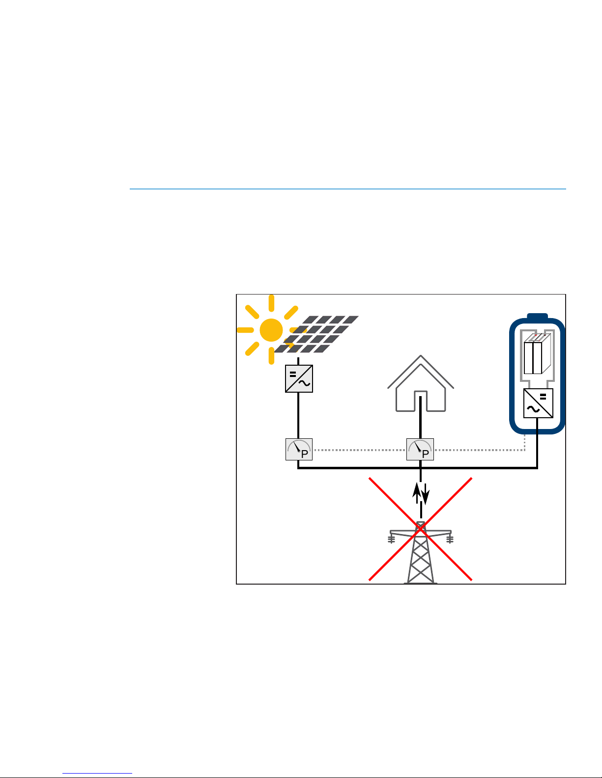
The storage system also acts as a backup power supply, meaning
that if the utility grid goes out, your appliances will remain
powered.
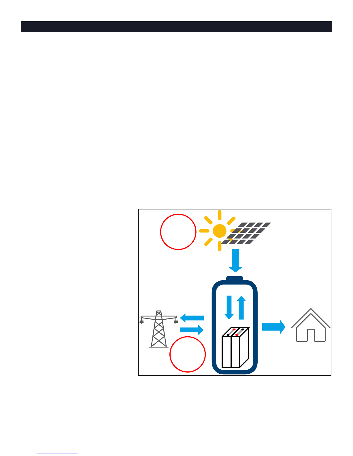
Fig. 1 Energy flow
The above illustration shows the storage system manages solar
power (1) and power from the utility grid (2) to maximize your
energy independence and savings on your power bill.
1
2
11
Modes of operation
The sonnenBatterie eco offers two complementary modes of
operation: Self-consumption and Backup. Self-consumption
mode ensures that you are using the power you generated even
when the utility grid power is available; backup mode makes
that self-generated power available in the event of a grid power
outage.
Many utility companies are moving to a Time of Use-based
billing scheme, in which electricity costs more during high-
demand time periods. The sonnenBatterie eco can maximize your
cost savings by using employing “rate arbitage” — using your
stored battery power during the high-cost part of the day and
recharging from solar and optionally with electricity purchased
from the grid at the lowest offered rates.
Self-consumption mode
The following illustrates the interaction between the storage
system, the PV system, and the utility grid in self-consumption
mode:
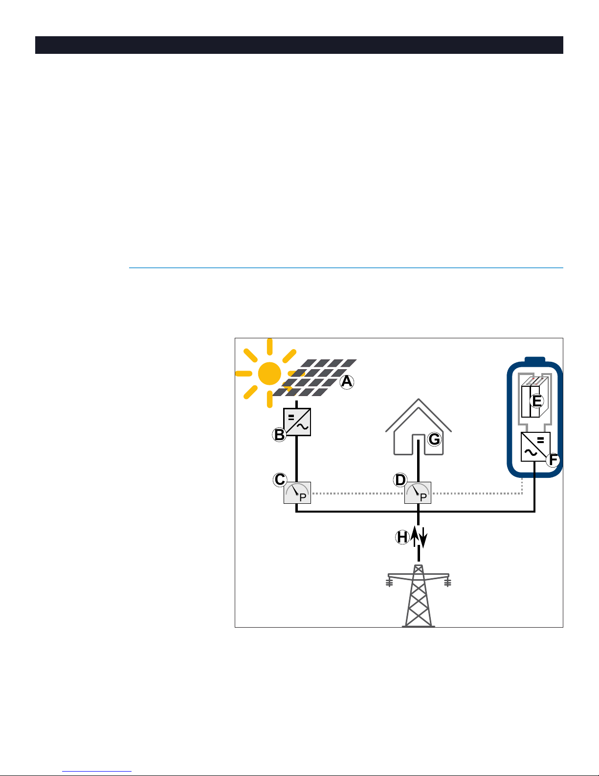
Fig. 2 Self-consumption mode
The DC power that is generated by the PV array (A) is converted
to AC power by means of an inverter (B). The meters (C) and (D)
measure the current electrical power in watts. The production
meter (C) measures the power production, the consumption
meter (D) measures the power consumption in the house.
If the production is higher than the consumption, the surplus
P
P
E
F
B
A
D
G
H
C
12
will be stored in the battery modules (E). The storage system’s
inverter (F) converts the AC power to DC power while the
battery modules (E) are charging.
When the production is lower than the consumption, electric
power will be released from the battery modules. The storage
system’s inverter (F) converts the DC power of the battery
modules (E) to AC power. The utility’s power meter (G),
measures the power supply and the power fed back to the grid (if
applicable).
Backup mode
In backup mode, the house is powered by the energy stored in
the battery modules and generated by the PV array. During that
time, the power from the PV array powers the house or charges
the battery modules, depending on production and consumption
levels. The storage system can also turn the PV array off if the
battery modules become fully charged.
P
P
Fig. 3 Backup mode
13
Turning the system on and off
In most cases, you will not need to turn the storage system on
or off. If you do need to turn the system on or off, follow the
directions below.
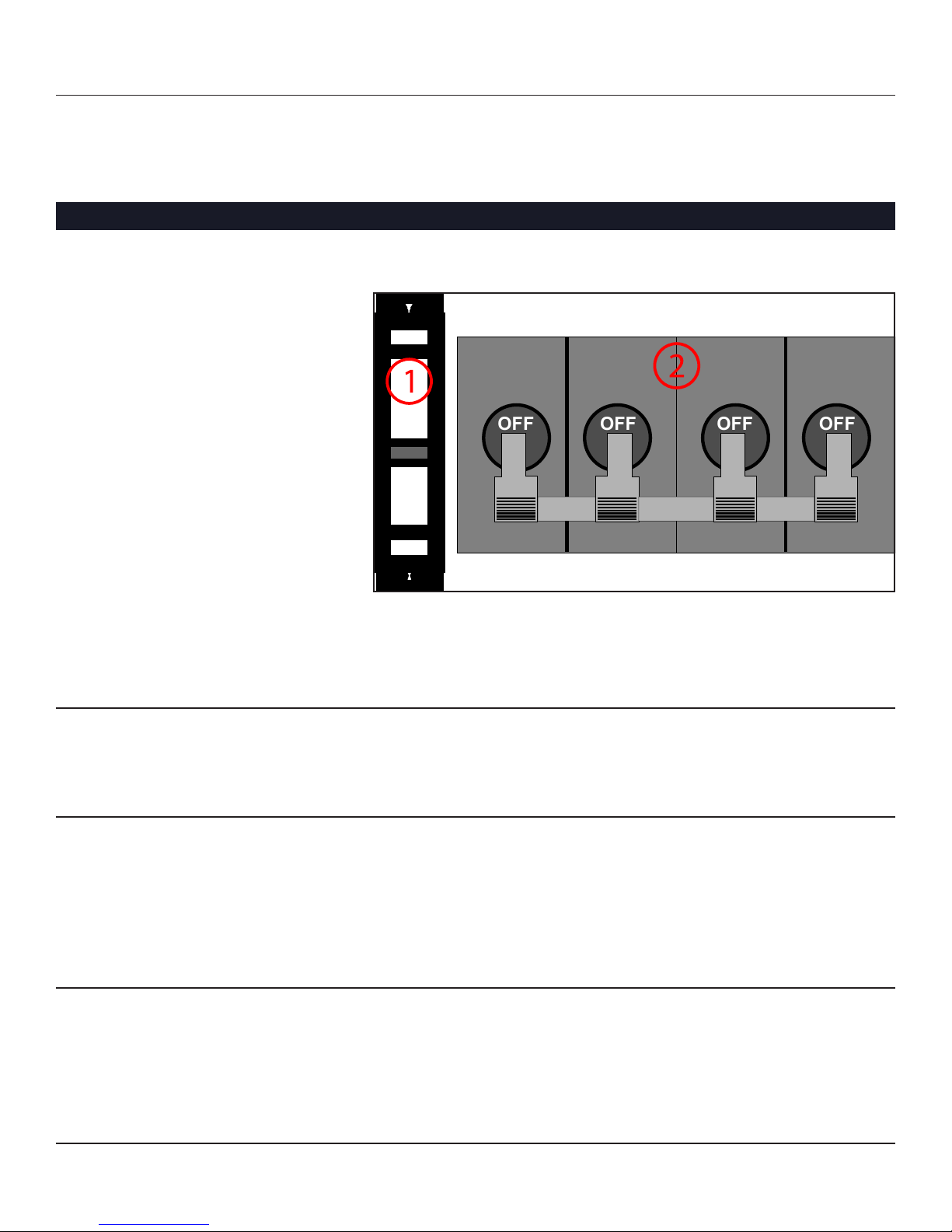
Turning the storage system on
The main DC circuit breaker F1 and the switch S1, located in the
interior of the main cabinet, control power to the system.
Fig. 4 Switch and circuit breaker
(S1) Switch
(F1) Main circuit breaker
Attention
Damage of the storage system by high currents!
High currents can damage components of the storage system if
the process is not followed properly.
▶Turn on the storage system only according to the steps below.
1. Make sure the emergency switch is turned on (if available).
2. Press switch S1 for at least 30 seconds and keep it pressed.
3. Turn on main circuit breaker F1 of the main cabinet.
4. Release switch S1.
After that, the storage system will boot up and perform a self-test.
Attention
Damage of the battery cells by deep discharge!
If the storage system is not connected to the utility grid, PV
system, or other sufficient power source, the battery modules can
be damaged by excessive and prolonged discharge.
▶Do not leave the storage system disconnected for longer than
six months
OFF
OFF
OFF
OFF

14
Shutting the storage system down
Attention
Damage of system parts by forced disconnect!
If there is no emergency:
▶Shut the storage system down.
If there is no emergency, do not turn off the storage system by
forcibly removing power, by turning off the DC circuit breaker,
or by using the battery emergency switch, as these methods may
result in undesirable behavior.
Shut down the storage system
Follow these steps to shut the storage system down properly:
1. Press power-off button
▶Press the red-framed power-off button in the upper right
corner of the start screen.
2. Confirm shut-down
▶Press again to confirm shut-down.
The shut down takes approximately 30 seconds.
Emergency switch-off
In case of an emergency, the storage system can be switched off by
the main circuit breaker F1 or the emergency switch (if installed).
Fig. 5 Circuit breaker
(S1) Switch
(F1) Main circuit breaker
▶In case of an emergency, switch off the main circuit breaker F1
in the interior of the main cabinet or the external emergency
switch (if installed).
▶Only switch off the main circuit breaker F1 if it can be reached
without danger.
OFF
OFF
OFF
OFF
Table of contents
Other Sonnen Home Automation manuals


