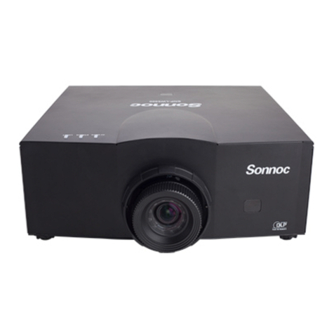
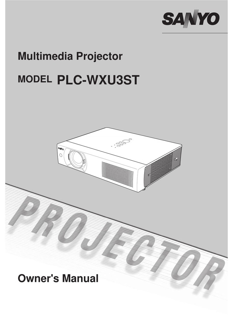
SONNOC SNP-LU11K User manual

SNP-LU11K / SNP-LU11K+ /
SNP-LU12K / SNP-LU12K+
USER MANUAL

The CD included with this printed manual contains an electronic copy in English. Please read all instructions before
using or servicing this product.
Die mit dieser gedruckten Anleitung gelieferte CD enthält eine elektronische Kopie in Deutsch. Bitte lesen Sie alle
Anweisungen, bevor Sie dieses Produkt verwenden oder warten.
Le DC fourni avec ce manuel imprimé contient une copie électronique en français. S'il vous plaît lire toutes les
instructions avant d'utiliser ou de réparer ce produit.
Il CD fornito con il manuale stampato contiene una copia elettronica in lingua italiano. Si prega di leggere tutte le
istruzioni prima di utilizzare o riparare questo prodotto.
El DC incluido con este manual impreso contiene una copia electrónica en español. Por favor, lea todas las
instrucciones antes de usar o dar servicio a este producto.

NOTICES
REGULATORY
The product has been tested and found to comply with the limits for a Class A digital device,
pursuant to Part 15 of the FCC Rules. These limits are designed to provide reasonable protection
against harmful interference when the product is operated in a commercial environment. The
product generates, uses, and can radiate radio frequency energy and, if not installed and used in
accordance with the instruction manual, may cause harmful interference to radio communications.
Operation of the product in a residential area is likely to cause harmful interference in which case
the user will be required to correct the interference at the user's own expense.
WARNING! Changes or modifications not expressly approved by the manufacturer could void the
user's authority to operate the product.
FOR COMMERCIAL USE ONLY - POUR USAGE COMMERCIAL UNIQUEMENT
THIS DEVICE COMPLIES WITH PART 15 OF THE FCC RULES. OPERATION IS SUBJECT TO
THE FOLLOWING 2 CONDITIONS: (1) THIS DEVICE MAY NOT CAUSE HARMFUL
INTERFERENCE (2) THIS DEVICE MUST ACCEPT ANY INTERFERENCE RECEIVED,
INCLUDING ANY INTERFERENCE THAT MAY CAUSE UNDESIRED OPERATION.
THIS CLASS A DIGITAL APPARATUS MEETS ALL REQUIREMENTS OF THE CANADIAN
INTERFERENCE-CAUSING EQUIPMENT REGULATIONS.
CET APPAREIL NUMÉRIQUE DE CLASSE A EST CONFORME AUX NORMES DÉFINIES DANS
LES RÉGLEMENTATIONS CANADIENNES SUR LES APPAREILS CAUSANT DES
INTERFÉRENCES RADIO (CANADIAN INTERFERENCE-CAUSING EQUIPMENT
REGULATIONS, ICES-003, CLASS A).

Table of Contents
Projector User Manual i
1. SAFETY
2. INTRODUCTION
2.1 Projector Components .................................................................................................. 2-1
2.2 Built-in Keypad..............................................................................................................2-4
2.3 Input/Output (I/O) Panel................................................................................................ 2-5
2.4 LED Status Indicators................................................................................................... 2-6
2.5 Remote Control............................................................................................................. 2-7
2.5.1 Projector Addressing........................................................................................ 2-9
2.5.2 Remote Control Keycode Table..................................................................... 2-10
3. SPECIFICATIONS
3.1 Inputs ............................................................................................................................ 3-1
3.2 PIP/PBP Compatibility .................................................................................................. 3-4
3.3 Key Features ................................................................................................................ 3-4
3.4 List of Components....................................................................................................... 3-4
3.5 Optional Accessories .................................................................................................... 3-5
3.6 Environment Condition ................................................................................................. 3-5
3.7 Regulatory .................................................................................................................... 3-6
3.8 Federal Communications Commission (FCC) Warning................................................ 3-7
3.9 OSD Tree...................................................................................................................... 3-8
4. INSTALLATION
4.1 Connect to Computer.................................................................................................... 4-1
4.2 Connect to Video Equipment ........................................................................................ 4-2
4.3 Turn the Projector On ................................................................................................... 4-3
4.4 Turn the Projector Off ................................................................................................... 4-4
4.5 Adjust the Projector Position......................................................................................... 4-4
4.6 Lens Offset ................................................................................................................... 4-5
4.7 Removing and Installing the Lens................................................................................. 4-7
5. OPERATION
5.1 Picture Menu.................................................................................................................5-2
5.2 Output Menu ................................................................................................................. 5-5
5.3 Setup Menu .................................................................................................................. 5-9
5.4 Option Menu ............................................................................................................... 5-11

Section 1: SAFETY
Projector User Manual
1-1
1. SAFETY
Read through this document in its entirety and understand all warnings and
precautions before attempting to operate the projector.
Important Information
Laser Safety Cautions:
• This product is classified as CLASS 1 LASER PRODUCT - RISK GROUP 2
of IEC 60825-1 : 2014, Complies with FDA Document issued on February
18, 2015 : Classification and Requirements for Laser Illuminated Projectors
(LIPs), complies with 21 CFR 1040.10 and 1040.11 as a Risk Group 2 , LIP
( Laser Illuminated Projector) as defined in IEC 62471:2006 except for
deviations pursuant to Laser Notice No. 50, dated June 24, 2007
• This projector has built-in Class 4 laser module. Disassembly or
modification is very dangerous and should never be attempted.
• Any operation or adjustment not specifically instructed by the user’s guide
creates the risk of hazardous laser radiation exposure.
• Do not open or disassemble the projector as this may cause damage by the
exposure of laser radiation.
• Do not stare into beam when the projector is on. The bright light may result
in permanent eye damage.
• When turning on the projector, make sure no one within projection range is
looking at the lens.
,(&&/$66/$6(5352'8&75,6.*5283
,(&352'8,7/$6(5'(&/$66(*5283('(5,648(
&RQIRUPHDX[QRUPHV&)5HWFRPPH*URXSHGHULVTXH
SURMHFWHXUODVHU/,3/DVHU,OOXPLQDWHG3URMHFWRUGpILQLSDU&(,
VDXIOHVH[FHSWLRQVFLWpHVGDQVOHGRFXPHQW/DVHU1RWLFH1GDWpGX-XLQ
$9(57,66(0(17
5D\RQQHPHQWRSWLTXHGDQJHUHX[SRWHQWLHOpPLVSDUFHSURGXLW1HSDVUHJDUGHU
GLUHFWHPHQWGDQVOHIDLVFHDX&HFLSRXUUDLWrWUHQRFLISRXUOHV\HX[
,(&䱢㾧ℰẎ⒨5*⍘晐䬰于
晋ṭ㠠㍕㾧ℰ⅓䬓⏞㗌㜆⹛㛯㗌Ḳⷕ⻩⣽䬍⏯&)5⑳⏳
,(&㈧⮁ḰḲ/,3㾧ℰ䅎㗵㉼⽘㜡ƌ5*⍘晐䬰于
㳏ヶ
㭋Ẏ⒨⏖僤ἁẎ䔆⍘晐㾧ℰ彷⯫˛寞⋦䛛妭㒴ὃℰ㝆ƏỌℴ⯠䜣䝂㍆⮚˛
&RPSOLHVZLWK&)5DQGDVD5LVN*URXS/,3
/DVHU,OOXPLQDWHG3URMHFWRUDVGHILQHGLQ,(&H[FHSWIRUGHYLDWLRQV
SXUVXDQWWR/DVHU1RWLFH1RGDWHG-XQH
&$87,21
3RVVLEO\KD]DUGRXVRSWLFDOUDGLDWLRQHPLWWHGIURPWKLVSURGXFW'RQRWVWDUHDW
RSHUDWLQJEHDP0D\EHKDUPIXOWRWKHH\HV

Section 1: SAFETY
Projector User Manual 1-2
• Without following the control, adjustment or operation procedure may
cause damage by the exposure of laser radiation.
• Adequate instructions for assembly, operation, and maintenance, including
clear warnings concerning precautions to avoid possible exposure to laser.
Installing the Projector Properly
• Please set the projector on nearly-level.
• Be sure to install the projector properly. Improper installation may reduce
the laser diode lifetime andeven cause a fire hazard.
• Caution in ceiling installation the projector:
- Only qualified personal is authorized for ceiling installation.
- We are not responsible for the hurt and damage caused by ceiling
bracket that purchased from unauthorized dealer even in warranty
period.
- Remove the ceiling bracket immediately while not use.
- While installing, torque screwdriver is suggested, don’t use electric or
impact-type screwdriver.
- Please read the manual of bracket for details.
- The bracket is subject to change without notice.
140mm
280mm
280mm102mm
310mm
4-M6x10
310mm 110mm99mm

Section 2: INTRODUCTION
Projector User Manual
2-1
2. INTRODUCTION
The product specified in this document is a high brightness, high-resolution
video/graphics 1-chip laser based projector. The projector is available in
WUXGA resolution. The projector utilizes Digital Light Processing (DLP®)
technology from Texas Instruments. It is primarily designed for fixed installation
markets.
2.1 Projector Components
Front View
Ind. Part Name Description
1 Front IR Receiver
Receives signals from the IR remote. Keep the signal
path to the sensor unobstructed for uninterrupted
communication with the projector.
2 Projection Lens Allows automated lens control and adjustment:
vertical and horizontal offsets, zoom and focus.
3 Adjustable Feet Raise or lower the feet to level the projector.
1
2
3

Section 2: INTRODUCTION
Projector Series User Manual 2-2
Rear View
Ind. Part Name Description
1 LED Status Indicators Displays the status of the projector.
2 Top IR Sensor
Receives signals from the IR remote. Keep the signal
path unobstructed for uninterrupted communication
with the projector.
3 Connector panel Connects the projector to external devices.
4 Power Switch Switch the power button to turn on/off the power
source.
5 Power Connector Connect to the supplied power adapter.
6 Kensington Lock Use to secure the projector to countertops, tables, etc.
7 Security bar Use to secure the projector.
8 Keypad Panel Controls the projector.
MENU INPUT
EXIT
LENS
FOCUS
ZOOM
ENTER
12
3
45678

Section 2: INTRODUCTION
Projector User Manual
2-3
Left View
Right View
Ind. Part Name Description
1 Inlet Vent Keep these vents unobstructed to prevent the
projector from overheating.
2 Outlet Vent Keep these vents unobstructed to prevent the
projector from overheating.
1
2

Section 2: INTRODUCTION
Projector Series User Manual 2-4
2.2 Built-in Keypad
Ind. Part Name Description
1 Power Turn the projector on or off.
2 Menu Display menus.
3 Exit Return to previous level or exit menus if at top level.
4 Input Select an input for the main or PIP/PBP image.
5 Enter Confirm a selection.
6 Arrow Keys • Adjust a setting UP or DOWN.
• Navigate within a menu.
7 Zoom Adjust zoom.
8 Focus Adjust focus.
9 Lens Adjust the lens vertical or horizontal offset setting.
MENU INPUT
EXIT
LENS
FOCUS
ZOOM
ENTER
1234
765
8
9

Section 2: INTRODUCTION
Projector User Manual
2-5
2.3 Input/Output (I/O) Panel
RS232 Pin Assignments
Ind. Connector Name Ind. Connector Name
1 3G-SDI IN 8 USB Type A (WIFI dongle)
2 DVI-D 9 3D SYNC IN
3 VGA IN 10 REMOTE IN
4 VGA OUT 11 RS-232C
5 HDMI OUT 12 LAN (Ethernet)
6 HDMI IN 13 HDBaseT
7 Mini USB (LAN FW Upgrade) 14 3D SYNC OUT
23456
87
121314
1
91011
Pin no. Spec.
(from projector side)
1N/A
2RXD
3TXD
4N/A
5GND
6N/A
7N/A
8N/A
9N/A
12345
6789

Section 2: INTRODUCTION
Projector Series User Manual 2-6
2.4 LED Status Indicators
The LED status indicators are located on the rear of the projector. Each LED is
defined below.
Message Light LED Status LED AV Mute LED
Green Orange Red Green Orange Red Green Orange
Standby State
Flashing
Power on
(Warm up)
Flashing
Power on &
Laser diode on Steady Steady Steady
Power off
(Cooling down)
Flashing
AV mute is off
(Image is
displayed)
Steady Steady Steady
AV mute is on
(Image is black) Steady Steady Steady
Projector
communication Steady
Flashing
Steady
Firmware upgrade
Flashing Flashing
Error
(Over temperature) Steady
Error (Fan failure)
Flashing

Section 2: INTRODUCTION
Projector User Manual
2-7
2.5 Remote Control
ON OFF
21 3
54 6
87 9
Gamma Bright Cont. PIP
0
Info
Mode
Auto
Input
Menu Exit
Hot Key
Shutter
(AV Mute)
Pattern
Focus
Lens H
Lens V
Keystone H
Keystone V
Zoom
Enter
16
17
18
20
21
22
23
24
1
19
2
3
4
5
6
7
8
9
10
11
12
13
14
15

Section 2: INTRODUCTION
Projector Series User Manual 2-8
Ind. Part Name Description
1 Power on Turn projector ON.
2 Number Keys Enter a number, such as a value for an IP address,
etc.
3 Info Display source image information.
4 Auto Automatically optimize image.
5 Enter • Select a highlighted menu item.
• Change or accept a value.
6ArrowKeys • Adjust a setting UP or DOWN.
• Navigate within a menu.
7 Menu Display menus.
8 Bright Adjust amount of light in the image.
9 Gamma Adjust mid-range levels.
10 Lens H Adjust the position of the image horizontally.
11 Lens V Adjust the position of the image vertically.
12 Keystone H Adjust the horizontal keystone.
13 Keystone V Adjust the vertical keystone.
14 Shutter (AV Mute) Display or blank the video image.
15 Hot Key Select your preset keys quickly.
16 OFF Turn projector OFF.
17 Mode Select the preset display mode.
18 Input Select an input for the main or PIP/PBP image.
19 Exit Return to previous level or exit menus if at top level.
20 Cont. Adjust difference between dark and light.
21 PIP Turn PIP/PBP ON/OFF.
22 Focus Adjust focus to improve image clarity as desired.
23 Zoom Adjust zoom to achieve a desired image size.
24 Pattern Display a test pattern.

Section 2: INTRODUCTION
Projector User Manual
2-9
2.5.1 Projector Addressing
The customer code has 100 groups.
a. the preset 1st group:
FACTORY_ID + REMOTE_CODE = 0xA0EB
b. the 2nd group until 100th group:
FACTORY_ID1 + REMOTE_CODE1 = 0xB010
FACTORY_ID1 + REMOTE_CODE2 = 0xB011
….
FACTORY_ID1 + REMOTE_CODE99 = 0xB072
The method to change the customer code and code table for ID Code 1 to 99 is
shown below:
NOTE:
The original code: Press "Hot key" for 3 sec, then release, enter 0 then enter 0 within 2 seconds.
ID Code Change mode Customer
code
1Press "Hot key" for 3 sec., release, enter “0” then enter “1”
within 2 sec. B010
2Press "Hot key" for 3 sec., release, enter “0” then enter “2”
within 2 sec. B011
3Press "Hot key" for 3 sec., release, enter “0” then enter “3”
within 2 sec. B012
…… …
10 Press "Hot key" for 3 sec., release, enter “1” then enter “0”
within 2 sec. B019
11 Press "Hot key" for 3 sec., release, enter “1” then enter “1”
within 2 sec. B01A
…… …
98 Press "Hot key" for 3 sec., release, enter “9” then enter “8”
within 2 sec. B071
99 Press "Hot key" for 3 sec., release, enter “9” then enter “9”
within 2 sec. B072

Section 2: INTRODUCTION
Projector Series User Manual 2-10
2.5.2 Remote Control Keycode Table
The keycode table for ID Code 0 is shown below:
Key
Position Key Legend Repeat
Format
Normal Function
Byte1 Byte2 Byte3 Byte4
1ONF1A0EB12ED
2 OFF F1 A0 EB 02 FD
3 1 F1 A0 EB 31 CE
4 2 F1 A0 EB 32 CD
5 3 F1 A0 EB 33 CC
6 4 F1 A0 EB 34 CB
7 5 F1 A0 EB 35 CA
8 6 F1 A0 EB 36 C9
9 7 F1 A0 EB 37 C8
10 8 F1 A0 EB 38 C7
11 9 F1 A0 EB 39 C6
12 INFO F1 A0 EB 4C B3
13 0 F1 A0 EB 30 CF
14 Mode F1 A0 EB 23 DC
15 Auto Sync F1 A0 EB 15 EA
16 Input F1 A0 EB 14 EB
17 UP F1 A0 EB 40 BF
18 LEFT F1 A0 EB 42 BD
19 Enter F1 A0 EB 13 EC
20 RIGHT F1 A0 EB 43 BC
21 DOWN F1 A0 EB 41 BE
22 Menu F1 A0 EB 1B E4
23 Exit F1 A0 EB 1D E2
24 Gamma F1 A0 EB 0A F5
25 Bright F1 A0 EB 0B F4
26 Contr F1 A0 EB 0C F3
27 PIP F1 A0 EB 0D F2
28 LENS H F1 A0 EB 0E F1
29 LENS H F1 A0 EB 0F F0
30 FOCUS F1 A0 EB 16 E9
31 LENS V F1 A0 EB 1E E1

Section 2: INTRODUCTION
Projector User Manual
2-11
32 LENS V F1 A0 EB 1F F0
33 FOCUS F1 A0 EB 17 E8
34 KEYSTONE H ( ) F1 A0 EB 2C D3
35 KEYSTONE H ( ) F1 A0 EB 2D D2
36 ZOOM F1 A0 EB 18 E7
37 KEYSTONE V ( ) F1 A0 EB 2E D1
38 KEYSTONE V ( ) F1 A0 EB 2F D0
39 ZOOM F1 A0 EB 19 E6
40 Shutter(AV Mute) F1 A0 EB 11 EE
41 Hot key F1 A0 EB 1A E5
42 Pattern F1 A0 EB 1C E3
Key
Position Key Legend Repeat
Format
Normal Function
Byte1 Byte2 Byte3 Byte4

Section 3: SPECIFICATIONS
Projector User Manual 3-1
3. SPECIFICATIONS
3.1 Inputs
Signal Type Resolution Frame Rate (Hz) QD881 VGA HDMI DVI HDBaseT 3G-SDI
PC
640x480 60 DMT0660 VVV V
640x480 72 DMT0672 VVV V
640x480 75 DMT0675 VVV V
640x480 85 DMT0685 VVV V
640x480 66.6 APP0667 VV V
720x400 70 IBM0770H VVV V
800x600 60 DMT0860 VVV V
800x600 72 DMT0872 VVV V
800x600 75 DMT0875 VVV V
800x600 85 DMT0885 VVV V
800x600 120 CVR0812 VVV V
832x624 75 8362A75 VVV V
848x480 50 CVT0850H VV V
848x480 60 CVT0860H VV V
848x480 75 CVT0875H VV V
848x480 85 CVT0885H VV V
1024x768 60 DMT1060 VVV V
1024x768 75 DMT1075 VVV V
1024x768 85 DMT1085 VVV V
1024x768 120 CVR1012 VVV V
1152x720 50 CVT1150D VV V
1152x720 60 CVT1160D VV V
1152x720 75 CVT1175D VV V
1152x720 85 CVT1185D VV V
1152x864 60 CVT1160 VVV V
1152x864 70 DMT1170 VVV V
1152x864 75 DMT1175 VVV V
1152x864 85 DMT1185 VVV V
1152x870 75 APP1175 VV V
1280x720 50 CVT1250H VV V
1280x720 60 CVT1260H VVV V
1280x720 75 CVT1275H VVV V
1280x720 85 CVT1285H VVV V
1280x720 120 VVV V
1280x768 60 CVT1260E VVV V
1280x768 75 CVT1275E VVV V
1280x768 85 CVT1285E VVV V
1280x800 50 CVT1250_ VVV V
1280x800 60 DMT1260D VVV V
1280x800 75 CVT1275_ VVV V
1280x800 85 CVT1285_ VVV V
1280x960 50 CVT1250 VV V

Section 3: SPECIFICATIONS
Projector User Manual
3-2
PC
1280x960 60 CVT1260 VVV V
1280x960 75 CVT1275 VVV V
1280x960 85 CVT1285 VVV V
1280x1024 50 CVT1250G VV V
1280x1024 60 DMT1260G VVV V
1280x1024 75 DMT1275G VVV V
1280x1024 85 DMT1285G VVV V
1360x768 50 CVT1350H VV V
1360x768 60 DMT1360H VV V
1360x768 75 CVT1375H VV V
1360x768 85 CVT1385H VV V
1366x768 60 DMR1360H VVV V
1400x1050 50 CVT1450 VV V
1400x1050 60 CVT1460 VV V
1400x1050 75 CVT1475 VVV V
1440x900 60 CVT1460D VVV V
1440x900 75 CVT1475D VV V
1600x900 60 DMR1660H VV V
1600x1200 60 DMT1660 VVV V
1680x1050 60 CVT1660D VVV V
1920x1080 50 CVT1950H VV V
1920x1080 60 CVR1960H VVV V
1920x1200RB 60 CVR1960D VVV V
1920x1200RB 50 CVT1950D VVV V
NTSC NTSC (M, 4.43) 60
PAL
PAL (B,G,H,I) 50
PAL (N) 50
PAL (M) 60
SECAM SECAM (M) 50
SDTV 480i 60 VVV V
576i 50 VVV V
EDTV 480p 60 VVV V
576p 50 VVV V
HDTV
1080i 25 VVV V
1080i 29 VVV V
1080i 30 VVV V
720p 50 VVV V
720p 59 VVV V
720p 60 VVV V
1080p 23 VVV V
1080p 24 VVV V
1080p 25 VVV V
1080p 29 VVV V
1080p 30 VVV V
1080p 50 VVV V
1080p 59 VVV V
Signal Type Resolution Frame Rate (Hz) QD881 VGA HDMI DVI HDBaseT 3G-SDI

Section 3: SPECIFICATIONS
Projector User Manual 3-3
NOTE:
"RB" means "reduced blanking".
HDTV 1080p 60 VVV V
Mandatory
3D
Frame Packing
1080p 24 V V
Frame Packing
720p 50 V V
Frame Packing
720p 60 V V
Side by Side
1080i 50 V V
Side by Side
1080i 60 V V
Top and Bottom
720p 50 V V
Top and Bottom
720p 60 V V
Top and Bottom
1080p 24 V V
Frame
sequential
3D
800x600 120 V V
1024x768 120 V V
1280x720 120 V V
1080p 50 V V
1080p 60 V V
1920X1200RB 50 V V
1920X1200RB 60 V V
SD-SDI
480i YcbCr422
10bit 59.94 V
576i YcbCr422
10bit 50 V
HD-SDI
720p YcbCr422
10bit
50 V
59.94 V
60 V
1080i YcbCr422
10bit
50 V
59.94 V
60 V
1080p
YcbCr422 10bit
23.98 V
24 V
25 V
29.97 V
30 V
1080sF
YcbCr422 10bit
25 V
29.97 V
30 V
3GA-SDI 1080p
YcbCr422 10bit
50 V
59.94 V
60 V
3GB-SDI
1080p
YcbCr422 10bi
With 352M
Payload ID
50 V
59.94 V
60 V
Signal Type Resolution Frame Rate (Hz) QD881 VGA HDMI DVI HDBaseT 3G-SDI
This manual suits for next models
2
Table of contents
Other SONNOC Projector manuals
