Sonosax SX-RC8+ User manual

SX-R4+ FADER
EXTENSION MODULE
SONOSAX
SX-RC8+
USER MANUAL
Version 1.2
February 2019
Audio equipment manufacturer
SONOSAX SAS S.A.
Ch. de la Naz 38
CH-10 2 Le Mont-sur-Lausanne
Switzerland
http://www.sonosax.ch

Table of Contents
1 Introduction................................................................................................................................... 3
1.1 Key Features.............................................................................................................. 3
1.2 Functional Block Diagram...........................................................................................3
2 Panel Descriptions........................................................................................................................ 4
2.1 Front Panel................................................................................................................. 4
2.2 Side Panels................................................................................................................ 4
3 Operating Instruction....................................................................................................................
3.1 Connecting to the SX-R4+..........................................................................................
3.2 Operating modes........................................................................................................
3.3 AES Breakout.............................................................................................................
3.4 Slate/Com Microphone Control...................................................................................6
3. Hirose Power Distribution...........................................................................................6
4 Specifications............................................................................................................................... 7
4.1 Microphone Preamplifier............................................................................................. 7
4.2 Power......................................................................................................................... 7
4.3 Mechanical................................................................................................................. 7
Connector Pin Assignments.......................................................................................................... 8
.1 3M MDR 26-pin..........................................................................................................8
.2 Headset/Headphones 3. mm jack..............................................................................8
.3 Power Hirose 4-pin.....................................................................................................8
.4 AES inputs TA3 male (mini-XLR)................................................................................8
SX-RC8+ User Manual 2/8

1 Introduction
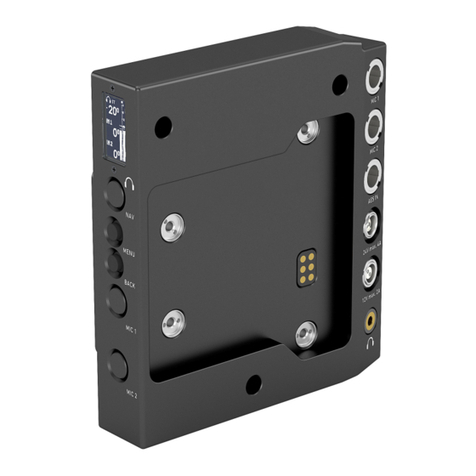
Congratulations for purchasing your SONOSAX SX-RC8+ fader extension module, a
dedicated front panel for the SX-R4+ providing 8 rotary faders with function switch to
extend mixing facilities in the field.
As with all SONOSAX products, the SX-RC8+ is build without any compromise in
quality, using only the best components available and passes severe quality controls.
The information and instructions contained in this manual are necessary to ensure
safe operations of your equipment and to maintain it in good working condition; please
read it carefully.
1 1 Key Features
Inputs / Outputs
•4x TA3 connectors used as AES breakout box for the multi-pin AES input
connector on the SX-R4+
•x Hirose 4 for power distribution
•Additional headphones/headset output with mic support
•Slate/Com microphone
1 2 Functional Block Diagram
POWER DISTRIBUTION
SX-RC8+ User Manual 3/8

2 Panel Descriptions
2 1 Front Panel
F1 F3 F5 F7
F2 F4 F6 F8
M
C C
F1 to F8
Fader with push on
C
Cut-out for shoulder strap
M
Internal Slate/Com microphone
2 2 Side Panels
H1 D1
H2
H3
H4 H5
D2
D3 D4
PM
LEFT RIGHT
H1 to H5
Power Distribution
P
Phones
D1 to D4
AES inputs TA3 male (mini-XLR). D4
(AES 7-8) is shared with MIC operation
M
3M MDR 26-pin for SX-R4+ interconnect
SX-RC8+ User Manual 4/8

3 Operating Instruction
3 1 Connecting to the SX-R4+
A 3M MDR 26-pin pin-to-pin cable is required to interconnect the SX-RC8+ to the SX-
R4+. The SX-RC8+ is powered by the SX-R4+ and operates as soon as it is
connected to it.
3 2 Operating modes
The SX-R4+ menu SETUP/POT SETUP
allow to select 3 different operating
modes:
•Input gains
•Fader -60 to +12 dB
•Fader -60 to +24 dB
Input gains apply to AES input 1 to 8.
Fader mode have two different curves:
•-60 to +12 dB
•-60 to +24 dB
Both curves mute when fader is closed.
Faders must be assigned in the SX-R4+
MIX menu.
To assign a fader, press the ASSIGN
button.
First, choose the fader to be assigned
using the rotary encoder.
Then, push all track or track pair buttons
where the fader is to be assigned.
Push again the ASSIGN button to disable
fader assignation.
3 3 AES Breakout
The 4 TA3 connectors are used as AES breakout box, allowing easy connection of
AES sources such as digital wireless receivers.
The 4th TA3 connector (AES 7-8) is shared with the Slate/Com microphone AES
output.
SX-RC8+ User Manual /8

3 4 Slate/Com Microphone Control
The SX-RC8+ includes a microphone preamplifier with automatic gain control and Low
Frequency Cut filter. User can choose between the front panel mic or an external
headset connected to the Headset/Headphones 3. mm jack.
The SX-RC8+ configuration is integrated
into the SX-R4+ touch interface.
The configuration panel is located on
SETUP/SYSTEM/MISC/RC8+
•MIC SOURCE are two mutually
exclusive buttons where the
microphone source is selected
•LIMITER GAIN and
THRESHOLD allow user to
control the automatic gain control
•POT POS NOISE REDUC.
should be enabled in noisy
environment where the SX-R4+
detects faulty faders movements.
Any push-button of the SX-R4+ or SX-
RC8+ can be used to control the
slate/com.
Enter the menu SETUP/SYSTEM/PUSH
BUTTONS to modify push-buttons
assignation.
The label “SX-RC8+ MIC” correspond to
the slate/com microphone enable action.
3 5 Hirose Power Distribution
The power distributor on the left panel is fully independent and does not need any
power for the SX-RC8+ to operate. There are x Hirose 4 connectors connected as
following:
POWER
SMBUS
Note: there is no connection between the SX-R4+ power for the SX-RC8+ and that
power distribution.
The optional solder jumpers on pins 2 & 3 are dedicated for a System Management
Bus (SMBUS). By default, these jumpers are open.
SX-RC8+ User Manual 6/8

4 Specifications
4 1 Microphone Preamplifier
Sampling Frequency 48 kHz
Bit Depth 16-bit
4 2 Power
Input Voltage +3.3 V on 3M MDR 26-pin
Power consumption 200 mW (mic OFF)
2 mW (mic ON)
4 3 Mechanical
Size (H x W x D) 200 x 0 x 7 mm
7.87 x 1.96 x 2.24 ‘’
Weight 363 g
0.80 lb
SX-RC8+ User Manual 7/8

5 Connector Pin Assignments
5 1 3M MDR 26-pin
13 1
1426
2 AES 1-2 (-)
3 AES 3-4 (-)
4 AES -6 (-)
AES 7-8 (-)
6 RS422 RX (-)
7 RS422 TX (-)
12 Headphones Right
1 AES 1-2 (+)
16 AES 3-4 (+)
17 AES -6 (+)
18 AES 7-8 (+)
19 RS422 RX (+)
20 RS422 TX (+)
21 DC 3.3V input
24 Headphones Ground
2 Headphones Left
1, 13,
14, 26
Digital ground
8 – 11,
22, 23
not connected
5 2 Headset/Headphones 3 5mm jack
5 3 Power Hirose 4-pin
5 4 AES inputs TA3 male (mini-XLR)
1
2
3
1 Ground
2 Signal (+)
3 Signal (-)
SX-RC8+ User Manual 8/8
Table of contents
Other Sonosax Control Unit manuals
Popular Control Unit manuals by other brands

FrSky
FrSky RB-25 instruction manual

Watts
Watts MINIMIXing Installation and operation manual

Burkert
Burkert Type 2000 quick start
Siemens
Siemens LMV 5 Series manual
TA Hydronics
TA Hydronics TWORETT Manifold assemblies
Federal Signal Corporation
Federal Signal Corporation 2001DC Installation, operation and servicing manual
Cisco
Cisco SCE8000 GBE installation guide

Acromag
Acromag EtherStax Series manual

InterMotive
InterMotive AFIS422VSX-B installation instructions
Keysight Technologies
Keysight Technologies M937 A Series Startup guide

Richter
Richter GR/F Series Installation and operating manual
AUMA
AUMA Aumatic AC 01.1 Operation instructions
