FrSky RB-25 User manual

Version
1.0
Instruction Manual for FrSky RB-25 & RB-25S
Add: F-4,Building C, Zhongxiu Technology Park, No.3 Yuanxi Road, Wuxi, 214125, Jiangsu, China Technical Support: [email protected]
Specifications
● Dimension: 53*40*16mm (L*W*H)
● Weight: 25.6g (RB-25) / 26.7g (RB-25S)
● Number of Channel Ports: 18 (PWM/FBUS/S.Port/SBUS Out)
● 3 RX Input Ports & 1 LED Indicator Port
Introduction
The RB-25/RB-25S builds on the success of the previous trusted Redundancy Bus Series by adding new
advanced features combined with a compact new design which meets the needs of users who want a flight-safe
system built in a smaller size unit.
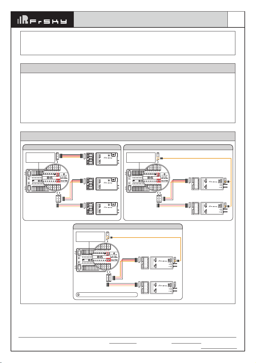
Triple Receiver Redundancy & Dual Power Input
RB-25/RB-25S has been designed to offer both dual-power and triple-receiver redundancy. This provides the
user triple receiver signal and telemetry redundancy by adding multiplex ports (RX1-3 IN / S.Port). Dual-power
provides a safe and efficient way to power the system with your power sources connected via a pair of standard
XT30 connections. The dual-power consumption system is designed to operate in balance mode, where it
consumes the power line from either power sources depending on which has the higher voltage.
Advanced Stabilizer (RB-25S)
The RB-25S offers an ADV Stabilizer function which is an upgrade over the original classical gyroscope
stabilization modes. The ADV Stabilizer offers an advanced mode that provides more programmable stabilized
channels and flexibility.
The classical stabilization mode has been enhanced with 5 additional stabilization channels, providing pin
mapping to each channel in the multiple flight modes like Stabilization, Auto-Level, Hover, and Knife-Edge with
an airplane model.
In the advanced stabilization mode, all the RB25S output pins are configurable for stabilization and additional
advanced features such as File Sharing, Programmable Parameters, and Developer Access, etc.
Diversified Sensor Telemetry
The RB-25/RB-25S also works as an extensive sensor module with various built-in sensors including diversified
telemetry. The RB-25S also includes the high-precision telemetry sensor for monitoring altitude, vertical speed,
etc. can be also used as an alternative to using a GR or S series receiver.
Power Switch Function
The built-in power switch function draws the support of using multiple types of external switches (e.g. NFC switch,
Pin Plug, etc.) that enables flexible options on how the power can be switched on/off without the need to
plug/unplug the battery connections.
16mm
40mm
53mm
10 11 12 13 14 15 16 17 18
9 8 7 6 5 4 3 2 1
CH9
CH8
CH7
CH6
CH5
CH4
CH3
CH2
CH1
RX1 S.P
LED
CH10
CH11
CH12
CH13
CH14
CH15
CH16
CH17
CH18
RX2
RX3
53mm
CH9
CH8
CH7
CH6
CH5
CH4
CH3
CH2
CH1
RX1 S.P
LED
CH10
CH11
CH12
CH13
CH14
CH15
CH16
CH17
CH18
RX2
RX3
10 11 12 13 14 15 16 17 18
9 8 7 6 5 4 3 2 1
Overview
Switch
Switch
GND
VOUT

Version
1.0
Instruction Manual for FrSky RB-25 & RB-25S
Add: F-4,Building C, Zhongxiu Technology Park, No.3 Yuanxi Road, Wuxi, 214125, Jiangsu, China Technical Support: [email protected]
● Operating Voltage: 4-10V (Recommend 2S Li batteries)
● Operating Current: ≤185mA@5V / Continuous Current: ≤30A
● Operating Temperature: -20°C~75°C
● Power Input Connector: XT30
Features
● Dual Power Balancing Consumption
● Triple Receiver Redundant Guarantee
● RX In | FBUS/SBUS/S.Port Auto Recognization
(Note: Only the S.Port on the RX1 channel port can be used to upgrade firmware.)
● Built-in Advanced Stabilization Functions (RB-25S)
● Built-in High-Precision Telemetry Sensor (Altitude, Vertical Speed, etc.) (RB-25S)
● Built-in Power Switch Function | Match with Different External Switches (Optional)
● Supports External LED Indication
● Compatible with FBUS/S.Port Products
Setup Guide - Redundant Signal Control with Telemetry
RX Input (RX1/RX2/RX3)
Port is SBUS/FBUS/S.Port
Auto Recognization
Only the S.Port on the RX1
channel port can be used
to upgrade firmware.
FBUS Capable Receiver
RECEIVER
10
9
10 11 12 13 14 15 16 17 18
9 8 7 6 5 4 3 2 1
10 11 12 13 14 15 16 17 18
9 8 7 6 5 4 3 2 1
FBUS
FBUS Capable Receiver
RECEIVER
10
9
FBUS
FBUS Capable Receiver
RECEIVER
10
9
FBUS
FBUS Capable Receiver Connections
RECEIVER
SBUS Capable Receiver
S.Port
10 11 12 13 14 15 16 17 18
9 8 7 6 5 4 3 2 1
10 11 12 13 14 15 16 17 18
9 8 7 6 5 4 3 2 1
RX Input (RX1/RX2/RX3)
Port is SBUS/FBUS/S.Port
Auto Recognization
SBUS OUT
SBUS OUT
Only the S.Port on the RX1
channel port can be used
to upgrade firmware.
ACCESS Receiver Connections vis SBUS
RECEIVER
SBUS Capable Receiver
RECEIVER
SBUS Capable Receiver
S.Port
10 11 12 13 14 15 16 17 18
9 8 7 6 5 4 3 2 1
10 11 12 13 14 15 16 17 18
9 8 7 6 5 4 3 2 1
RX Input (RX1/RX2/RX3)
Port is SBUS/FBUS/S.Port
Auto Recognization
SBUS OUT
SBUS OUT
Only the S.Port on the RX1
channel port can be used
to upgrade firmware.
ACCST Receiver Connections vis SBUS
RECEIVER
SBUS Capable Receiver
Telemetry redundancy is not capable while working with ACCST receivers.

Version
1.0
Instruction Manual for FrSky RB-25 & RB-25S
Add: F-4,Building C, Zhongxiu Technology Park, No.3 Yuanxi Road, Wuxi, 214125, Jiangsu, China Technical Support: [email protected]
Basic Step Guides-Stabilization Function (RB-25S)
a. Model Creation & Make sure the connected receiver is bound to the radio;
b. Ensure stabilization is enabled & Calibrate the gyroscope sensor of the device;
c. Servo connection & Build the stabilization device to the model;
d. Set up the mixer channel and radio switches;
e. Determine the [Wing Type] & [Mounting Type];
f. Check the stabilized channel outputs of the receiver in the Auto-Level mode;
g. Check the stick control of the transmitter in the manual mode;
h. Self-Check of the receiver;
I. Failsafe setting.
Setup Guide - Dual Power Redundancy
Balance Mode - When the dual batteries are plugged into the RB flight-safe system the Power Redundancy
function is automatically activated. The system is designed to use the battery line from the higher voltage allowing
the balancing of power consumption across both batteries.
Note:
1. Please ensure the battery is plugged into VBAT1 while using the single battery.
2. Please ensure that both battery’s output power is not lower than the power needed for the connected
devices, otherwise there will be insufficient power supply for the devices.
Move to [RB25S Calibration] tool and calibrate the gyroscope sensor
1. The gyroscope of device (6 surfaces) must be calibrated before mounting into the model. Please place the
device on a flat ground or a table, and follow the instruction steps below to calibrate the gyrosope sensor;
2. Make sure the stabilization device with the Logo label side facing upwards laying on the desktop, move to the
radio and enter the [RB25S Calibration] tool, and select "click to confirm". At this moment, the yellow LED light
will flash until it lits off, then follow the prompts to calibrate the sensor;
3. Complete the calibration of all the device surfaces. Ensure the values of each axis (X, Y, Z, Mod) is about
1.000 while placing the device in the corresponding direction, and the deviation could be ±0.1;
4. The calibration is completed if all the steps above are done.
Gyroscope Sensor Calibration (RB-25S)
[System] → [RB25S Stab] [RB25S Stab] → [Stabilizing] → [On]
Ensure the RB25S stabilization function is enabled.

Version
1.0
Instruction Manual for FrSky RB-25 & RB-25S
Add: F-4,Building C, Zhongxiu Technology Park, No.3 Yuanxi Road, Wuxi, 214125, Jiangsu, China Technical Support: [email protected]

Version
1.0
Instruction Manual for FrSky RB-25 & RB-25S
Add: F-4,Building C, Zhongxiu Technology Park, No.3 Yuanxi Road, Wuxi, 214125, Jiangsu, China Technical Support: [email protected]
Connect the servos to the ports of the stabilization device according to the Channel List.
Servo connection & Build the device to the model (RB-25S)
Number of Channel
CH1
CH2
CH3
CH4
CH5
CH6
CH7
CH8
CH9
CH10
CH11
CH12
CH13
CH14&CH15
CH16
Corresponding parts
on the model
AIL 1
ELE 1
THR
RUD
AIL 2
ELE 2
AIL 3
ELE 3
RUD 2
AIL 4
ELE 4
User-defined
User-defined
User-defined
User-defined
Full name
Aileron
Elevator
Throttle
Rudder
Aileron
Elevator
Aileron
Elevator
Rudder
Aileron
Elevator
Gyro gain adjustment
Flight modes
Emergency mode
Gyro gain adjustment of CH13: When the the value of CH13 is in the center, the gain is zero. The gain increases
as the value get bigger. Until the value is ±100%, the gain reaches maximum.
Note:
RX1/S.Port is used to do the firmware upgrade and parameter settings by the S.Port tool or ETHOS radio.
Note:
Please make sure the side with the External Switch Port forwards the nose
direction of airplane model, and with a Single Screw Tab backward.
Attentions
CH1~CH12 should be connected to the corresponding servos.
Set up the mixer channel and radio switches
Refer to the Channel List to set the channel and switches. The switch setting of CH13-16 on the picture is for reference.
Forward
Backward

Version
1.0
Instruction Manual for FrSky RB-25 & RB-25S
Add: F-4,Building C, Zhongxiu Technology Park, No.3 Yuanxi Road, Wuxi, 214125, Jiangsu, China Technical Support: [email protected]
3
2
1
2
1
4
3
[Gain] and [Offset] configurations of flight modes
Gain - Stab Mode
Gain - Auto-Level Mode
Gain - Hover Mode
1
2
3
4
1
2
3
Gain - Knife Mode
Angle Offset - Auto-Level Mode
Angle Offset - Hover Mode
Angle Offset - Knife Mode
1
2
Wing Type
Mounting Type
1
2
Move to the [RB25S Stab] tool, determine the [WingType] & [Mounting Type];
Check whether the reaction of the wing servo is in line with the flight attitude caption below in the
[Auto-Level] mode. If not, please try to invert the corresponding channel output in the [RB25S Stab]
tool.
Inspection of flight attitude
To ensure flight safety, checking the compensation direction of the model is strongly recommended.
Activating auto level mode will produce a strong deflection on AIL and ELE, which is used to check the response
of aileron and elevator. Also, activating Knife-edge and Hover mode will have the same reaction on the rudder.

Version
1.0
Instruction Manual for FrSky RB-25 & RB-25S
Add: F-4,Building C, Zhongxiu Technology Park, No.3 Yuanxi Road, Wuxi, 214125, Jiangsu, China Technical Support: [email protected]
When the plane is rotated up or down
(Pitch), elevators should have the correcting
actions as illustrated.
When the plane is rotated left or right (Roll),
ailerons should have the correcting actions
as illustrated.
When the plane is rotated to left or right
(Yaw), rudders should have the correcting
actions as illustrated.
Check whether the reaction of the wing servo is in line with the radio stick operation in the [Manual]
mode. If not, please try to invert the corresponding channel output by pressing the channel bar in the
[Output] tool.
Note:
If the compensation direction is incorrect, please reverse the corresponding channel as illustrated
above through the RB25S Stab tool.
After changing the compensation direction, make sure to check it again on the actual model.

How to set the flight modes (RB-25S)
Quick Mode
It supports stabilization mode, auto-level mode, and manual (Gyroscope is off) mode and configured through
CH14. What’s more, an emergency mode is added to configure automatic level mode default through CH16.
The precise configuration is written below.
Enable the Quick Mode in the [RB25S] tool.
Note: The default mode of RB-25S is Quick Mode.
- If Quick Mode is applied, there is no Knife
Edge or (3D) Hover Mode.
- CH15 is not used when using Quick Mode.
Version
1.0
Instruction Manual for FrSky RB-25 & RB-25S
Add: F-4,Building C, Zhongxiu Technology Park, No.3 Yuanxi Road, Wuxi, 214125, Jiangsu, China Technical Support: [email protected]
Self Check (RB-25S)
1. Put the throttle to 0, and keep the other channels in the center position.
2. Move to [
System
] and enter the [RB25S Stab] tool to turn on [Self Check], then the blue LED light turns on.
Once the blue LED starts flashing, we can calibrate the maximum travel of stick channels (excluding the
throttle channel).
3. If the calibration is completed, the LED turns off and the servos react left and right to indicate that the
calibration process is completed.
Note: To do the Self-Check of the stabilization device, please ensure the stabilization function is
enabled. Enter the [RB25S Stab] tool and turn On the [Stabilizing], then quit the [RB25S Stab] tool
and back into this tool again, now the [Self-Check] function is capable to enable.
Do the Self-Check in the [RB25S Stab] tool. [System] → [RB25S Stab] → [Self-Check]
LED Working State
External Blue LED
ON
OFF
Flash
State (Self-check)
In process
Self-check is completed
Max & Min of channels in detecting
The external LED indicator can be connected to the LED port while the gyroscope sensor is enabled.

Version
1.0
Instruction Manual for FrSky RB-25 & RB-25S
Add: F-4,Building C, Zhongxiu Technology Park, No.3 Yuanxi Road, Wuxi, 214125, Jiangsu, China Technical Support: [email protected]
Conventional Model
Layout
CH14 SW-Mid
Off
CH14 (3 pos SW)
CH15 (3 pos SW)
Stabilization
CH14>M+H
(CH14 SW Down)
M-H<CH15<M+H
(CH15 SW Mid)
Automatic level
CH14>M+H
(CH14 SW Down)
CH15>M+H
(CH15 SW Down)
Hover
CH14>M+H
(CH14 SW Down)
CH15<M-H
(CH15 SW Up)
Knife-Edge
CH14<M-H
(CH14 SW Up)
M-H<CH15<M+H
(CH15 SW Mid)
Flight mode
Model Configuration Reference (RB-25S)
Note:
M:
represents a neutral signal period (1500μs)
H:
represents the time of required signal change to activate the mode (50μs). When the factory settings are
selected, the switch position shown above represents the required modes.
CH14 SW-Mid
Off
CH16 SW Down
Emergency
Mode
CH14 SW Down
&
CH15 SW Mid
Stabilization
CH14 SW Down
&
CH15 SW Down
Automatic
level
CH14 SW Down
&
CH15 SW Up
Hover
CH14 SW Up
&
CH15 SW Mid
Knife-Edge
CH14 (3 pos SW)
CH15 (3 pos SW)
CH16 (3 pos SW)
Flight mode
Conventional Mode
It supports stabilization mode and manual
(Gyroscope is off)
mode and configured through CH14&15. What’s
more, an
Emergency
mode is added to configure automatic level mode default through CH16. The precise
configuration is Written below.
Flight Mode
None
Stabilization Mode
Automatical Level Mode
Emergency Mode (Automatic Level Mode)
Position
SW Down
SW Mid
SW Up
SW Down
Channel
CH14 (3 pos SW)
CH16 (2 pos SW)
The stabilization devices fit multiple types of models, the model type can be changed via different tools (like STAB
RX.lua, ETHOS lua tool, etc.).

Version
1.0
Instruction Manual for FrSky RB-25 & RB-25S
Add: F-4,Building C, Zhongxiu Technology Park, No.3 Yuanxi Road, Wuxi, 214125, Jiangsu, China Technical Support: [email protected]
Layout of Delta wing / Flying wing Layout of V-tail
Delta wing & Flying wing & V-tail
1. When Delta wing/Flying wing is selected, the signal produced by the transmitter should be without active mixes
on the channels related to AIL and ELE. RB-25S will mix the AIL (CH1) and ELE (CH2) input signal with a fixed
mix percentage automatically.
2. When V-tail type is selected, the signal produced by the transmitter should be without active mixes on the
channels related to ELE and RUD. RB-25S will mix the ELE (CH2) and RUD (CH4) input signal with a fixed mix
percentage automatically.
Stabilization:
When the model is activated, RB-25S will compensate with external forces (wind) as soon as
receiving commands from the transmitter. This function is used to enhance the stability of the model on three axis
(Pitch, Roll, YAW). CH13 could be used to adjust gyro gain by assigning a knob or a slider, changing the sensitivi-
ty of the counteracting signal produced by the internal three-axis gyroscope.
Automatic level:
When the mode is activated, RB-25S will make the model return to level orientation with internal
three-axis accelerometer and three-axis gyroscope on AIL and ELE channels after the sticks being released to
neutral. RUD channel works in stabilization mode only.
Hover:
When the mode is activated, RB-25S will make the nose of the model straight up with internal three-axis
accelerometer and three-axis gyroscope on RUD and ELE channels (ELE and RUD inputs are not required).
Under this mode, AIL is used to control the rotation of the model and THR adjust the altitude. AIL channel works
in stabilization mode only.
Knife-egde mode:
When the mode is activated, RB-25S will roll the plane on a certain side (wing points up) with
internal three-axis accelerometer and three-axis gyroscope on RUD and AIL channels.Thus, AIL inputs are not
required. While the mode steering is done with ELE, altitude will be maintained with THR/RUD. ELE channel
operates in stabilization mode only.
Off:
When the mode is activated, RB-25S will transmit the received commands produced by the transmitter to the
model without compensating.
Flight mode Stabilization Auto Level Off
CH14 CH14>M+H
(CH14 SW Down)
CH14<M-H
(CH14 SW Up) CH14 SW-Mid
The available flight modes can be assigned to CH14 with a three-position switch.

Version
1.0
Instruction Manual for FrSky RB-25 & RB-25S
Add: F-4,Building C, Zhongxiu Technology Park, No.3 Yuanxi Road, Wuxi, 214125, Jiangsu, China Technical Support: [email protected]
How to switch the S.Port/SBUS/FBUS
Select the FBUS/S.Port/SBUS for the channel ports.Enter [RB25 | RB25S Config] and turn to Channel
Config 2/3 page
RB25S Config
Enter [RB25 | RB25S Config] and turn to Failsafe
Config 3/3 page.
The programmed channel will output the setted
Failsafe value before losing the control link.
How to set Failsafe
RB25S Config
This manual suits for next models
1
Table of contents
Other FrSky Control Unit manuals

FrSky
FrSky TWIN Lite Pro User manual

FrSky
FrSky R9M 2019 User manual

FrSky
FrSky ESC Neuron 40 User manual

FrSky
FrSky XHT User manual

FrSky
FrSky TANDEM X20 Pro User manual

FrSky
FrSky R9M Lite Pro User manual

FrSky
FrSky R9M Lite Pro User manual

FrSky
FrSky Neuron 60 User manual

FrSky
FrSky XJT Lite D8 User manual

FrSky
FrSky FWTM User manual
Popular Control Unit manuals by other brands

Dräger
Dräger PAS ASV Instructions for use

CALEFFI
CALEFFI 521352A Installation and commissioning manual

Mitsubishi Electric
Mitsubishi Electric Q06CCPU-V-H01 user manual

Yoshitake
Yoshitake BLV-2SF product manual

Siemens
Siemens SINUMERIK 840D sl Configuration manual

Balluff
Balluff BNI PBS-507-001-Z011 user guide