InterMotive AFIS422VSX-B User manual
An ISO 9001:2008 Registered Company
AFIS422VSX-B Advanced Fast Idle System - Transit Application
2009-2018 Ford -Series, all engines
2009-2010 Ford F-250 - F-550, all engines
2014-2018 Ford F53/F59, 6.8L engine
2014-2016 Ford Transit Connect
2009-2017 Chevrolet xpress / GMC Savana
2015-2017 Chevrolet Silverado / Sierra
2011-2014 American General MV-1 4.6L
2016-2017 Isuzu NPR
Overview
The Advanced Fast Idle System (AFIS) elevates engine idle speed in response to a number of triggers in
order to assist electrical or mechanical systems on the vehicle.
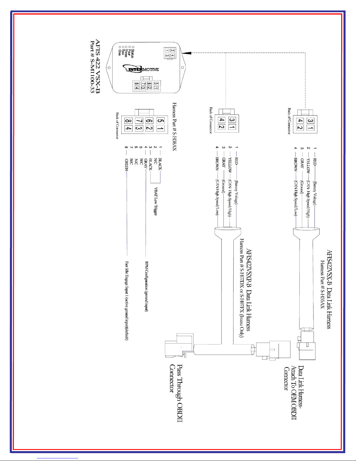
Options
AFIS422 SX-B — Single OBDII connector Data Link Harness
AFIS422 SX-BP — Two connector “T” Data Link harness
AFIS422 SX-BIP — Two connector white panel mount “T” Data Link harness
InterMotive Inc.
12840 Earhart Avenue
Auburn, CA 95602
Phone: (530) 823-1048
Fax: (530) 823-1516
Page 1 of 6
www.intermotive.net
AFIS422 SX-B-021318-INS
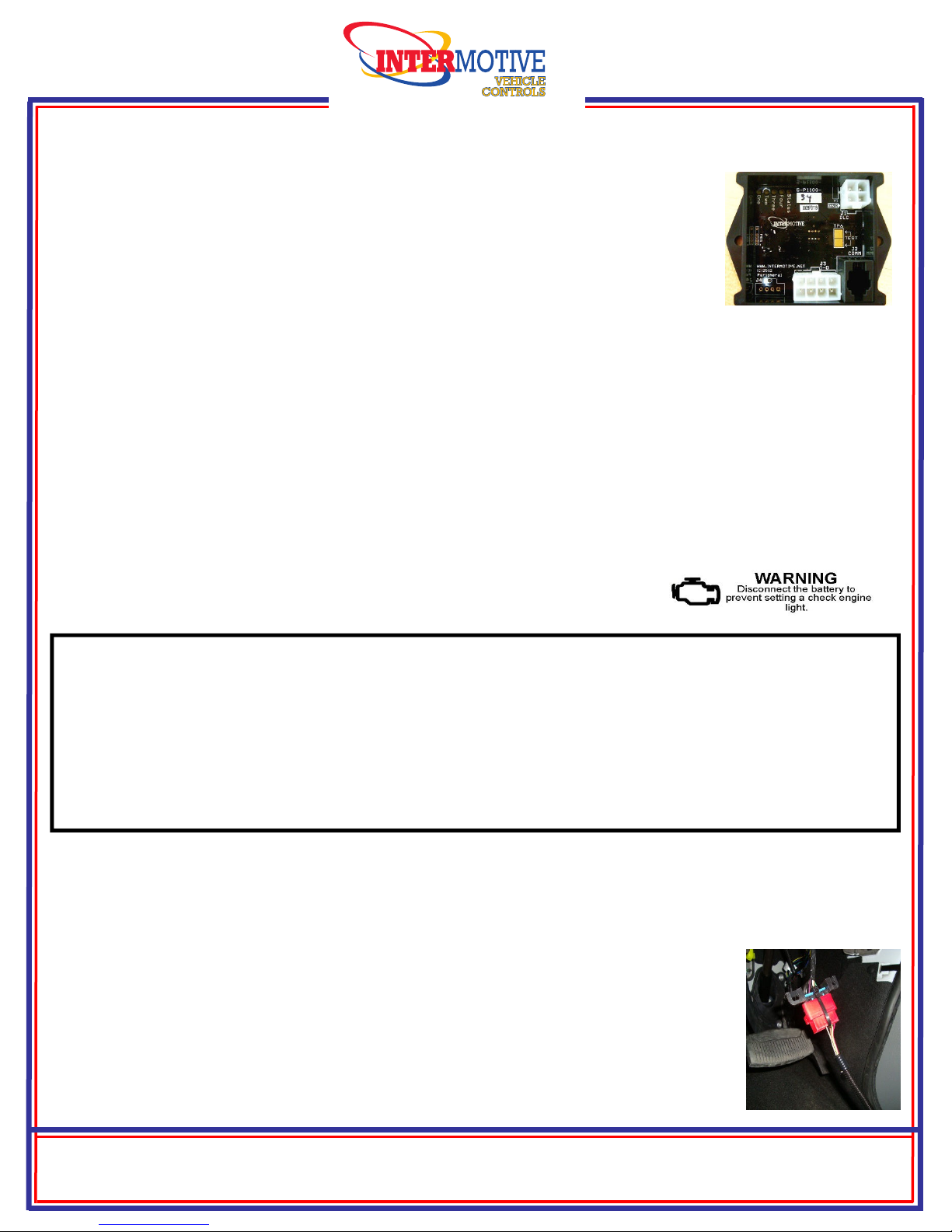
Data Link Harness (4-Pin Connector)
1. Locate the vehicle’s OBDII Data Link Connector , mounted below the lower left dash
panel. Plug the Red connector from the AFIS Data Link Harness into the vehicle OBDII
connector. Ensure the connection is fully seated and secured with the supplied wire tie.
2. Secure the AFIS Data Link harness so that it does not hang below the lower dash and
plug the (4-pin connector) from the Data Link Harness into the 4-Pin connector on the
AFIS module.
AFIS422 Module
Remove the lower dash panel below the steering column area and find a suitable location to mount
the AFIS422 module. Locate the module in an area away from external heat sources (engine heat,
heater ducts, etc.). Do not mount the module until all wire harnesses are routed and secure. The last
step of the installation is to mount the module.
Installation Instructions
Disconnect vehicle battery before proceeding with installation.
IMPORTANT—R AD B FOR INSTALLATION
It is the installer’s responsibility to route and secure all wiring harnesses where they cannot be damaged
by sharp objects, mechanical moving parts and high heat sources. Failure to do so could result in damage
to the system or vehicle and create possible safety concerns for the operator and passengers.
Avoid placing the module where it could encounter strong magnetic fields from high current cabling
connected to motors, solenoids, etc. Avoid radio frequency energy from antennas or inverters next to
the module. Avoid high voltage spikes in vehicle wiring by always using diode clamped relays when
installing upfitter circuits.
InterMotive Inc.
12840 Earhart Avenue
Auburn, CA 95602
Phone: (530) 823-1048
Fax: (530) 823-1516
Page 2 of 6
www.intermotive.net
AFIS422 SX-B-021318-INS
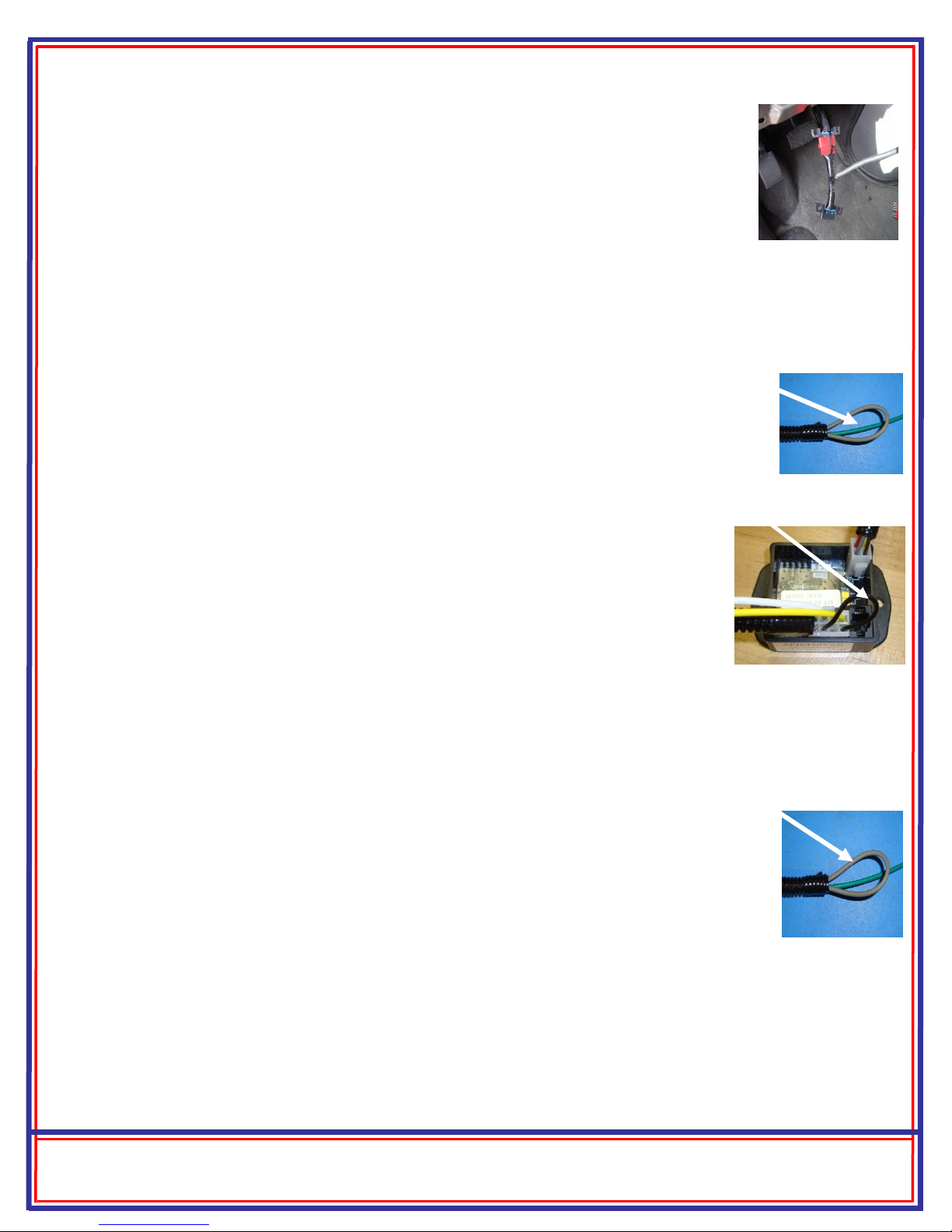
VBAT Low Fast Idle Trigger Disable— Black wire loop
The system is configured from the factory for Fast Idle to be triggered when the battery
voltage ( BAT) drops below 12.5 . If the BAT Low Fast Idle Trigger is not desired, it
may be disabled by cutting the Black wire (loop) on the 8-Pin connector between Pin #1
& Pin #3.
Configurable Idle Speed - Gray wire
The AFIS422 SX-B allows the user to change the fast idle RPM during installation. The default speed is
1500 RPM gas / 1200 Diesel, but the user can select any speed between 900 RPM and 2000 RPM in 50
RPM increments. To change idle speed:
1. Locate the Gray wire in the harness which connects to the 8 pin Molex connector.
2. Pull this wire out of the loom to expose the bare copper end.
3. Place the vehicle in Fast Idle by grounding the Manual Trigger Green wire. With the engine
in Fast Idle, momentarily grounding the Gray wire (RPM Configuration input) increases the
idle speed by 50 RPM. When the idle speed reaches the maximum allowable speed for the
particular engine, it will roll back around to 900 RPM. Wherever the user stops, this RPM
becomes the new default Fast Idle speed, even through key cycles.
4. After the vehicle is set to the desired fast idle speed, insert the end of the Gray wire into the harness tubing
and use tape to secure.
Note: Some vehicle PCM’s will limit Fast Idle to less than 2000 RPM. Continue momentarily grounding the
Gray wire and the RPM will eventually roll back around to 900 RPM. Do not leave the RPM’s set in a range
that the engine RPM is not responding to, as this may cause Fast Idle issues.
AFIS Harness (8-Pin Connector) Fast Idle ngage Input, Green wire
1. Attach the AFIS Harness connector Pin #8 Green wire to any equipment that provides a
ground signal when the fast idle needs to be engaged. (PTO, pump, etc.). Note: The
Green wire can also be connected to equipment providing a 12 signal, if programmed.
See below for programming instructions.
2. Plug the 8-pin connector from the AFIS Harness into the 8-Pin connector on the module.
AFIS422VSX-BP/BIP “T” Data Link Harness
1. Locate the vehicle OBDII Data Link Connector, mounted below the lower left dash
panel.
2. Remove the mounting screws for the OBDII connector. Plug the Red connector from
the AFIS422 SX-BP Data Link Harness into the vehicle’s OBDII connector. Ensure
the connection is fully seated and secure with the supplied wire tie.
3. Mount the Black pass through connector from the AFIS422 SX-BP Data Link Harness
in the former location of the vehicle’s OBDII connector.
4. Secure the AFIS422 SXP-B Data Link harness so that it does not hang below the lower dash
and plug the 4-pin connector from the Data Link Harness into the 4-Pin connector on the
AFIS422 SX-B module.

InterMotive Inc.
12840 Earhart Avenue
Auburn, CA 95602
Phone: (530) 823-1048
Fax: (530) 823-1516
Page 3 of 6
www.intermotive.net
AFIS422 SX-B-021318-INS
Park Brake Fast Idle Trigger nable/Disable
The AFIS422 SX-B is configured from the factory for Fast Idle not to be triggered when the Park
Brake is applied. If the Park Brake Fast Idle trigger is desired, it may be enabled (or disabled) by the
following procedure:
With key on, place the transmission in neutral, apply the Park Brake and press the Service Brake three times
within 5 seconds. Upon successful reprogramming, the on-board LEDs will briefly flash as a confirmation.
The user must cycle the key for the change to take affect.
A/C Fast Idle Trigger
The system is configured from the factory for Fast Idle to be triggered when the A/C clutch is engaged and
will stay engaged until the next key cycle, or a precondition is violated.
Fast Idle Pin-8 Trigger, Active: Ground or 12V signal nable/Disable
The module is configured from the factory for an active ground fast idle trigger. To change this to an active
12 trigger:
Turn the key on, place the transmission in neutral, apply the Service Brake, pull out on the Park Brake,
release and apply the Park Brake four times within 5 seconds. Upon successful reprogramming, the LEDs
will flash as a confirmation. The user must cycle the key for the change to take affect. Repeat to reverse
back to a ground trigger.
InterMotive Inc.
12840 Earhart Avenue
Auburn, CA 95602
Phone: (530) 823-1048
Fax: (530) 823-1516
Page 4 of 6
www.intermotive.net
AFIS422 SX-B-021318-OP
Post Installation System Operation Test
Perform the following tests before mounting the module, to allow easy viewing of the diagnostic LED’s, if
needed.
1. Place transmission in Park and start the engine. ehicle may enter Fast Idle if BAT is low. Either wait
to see if the battery charges and Fast Idle stops, or place a charger on the vehicle to disable the BAT
low trigger to allow testing of other triggers.
2. Manually engage Fast Idle by having aftermarket vehicle equipment ground the Green wire. Engine speed
will increase to the set RPM level. If this does not occur, check harness connections. Also see diagnostics
below.
3. Assuming Fast Idle engaged, keep the Green wire grounded, and depress the Service Brake for 1 second.
Fast idle will temporarily disengage anytime the Service Brake is depressed, but will automatically reengage
after approximately 2 seconds once the Brake pedal is released.
4. Place transmission shift lever in the “Neutral” position. (Green wire still grounded). The system must not
activate Fast Idle.
The AFIS422VSX-B is properly installed only if it passes all of the above steps.
Module Mounting
Ensure all harnesses are properly connected and routed and are not hanging below the dash area. Mount the
AFIS422 SX-B module using screws or double sided tape and reinstall all panels.
AFIS Status Codes
Status Code Description
1-1 Ready for fast idle
2-3 Triggered: Parking Brake
2-4 Triggered: BAT Low
2-8 Triggered: Manual Input
3-1 RPM > 2800
3-2 RPM < 200
3-3 TR not = to PARK
3-4 SS not = to 0 MPH
3-5 Service Brake applied
3-7 Unsafe; Need to cycle TR
3-8 ECT > 230ºF
2-5 Triggered: A/C Boost
Fast Idle Status Codes
Status Codes provide the current status of
the Fast Idle system. The on-board
“Status” LED will flash a 2-digit code as
shown in the table. The first digit will
flash, wait half a second, flash the second
digit, then wait one second before the
next code. The Status Codes continue to
flash until the module is reset (cycle key),
or the test input is momentarily grounded
again.
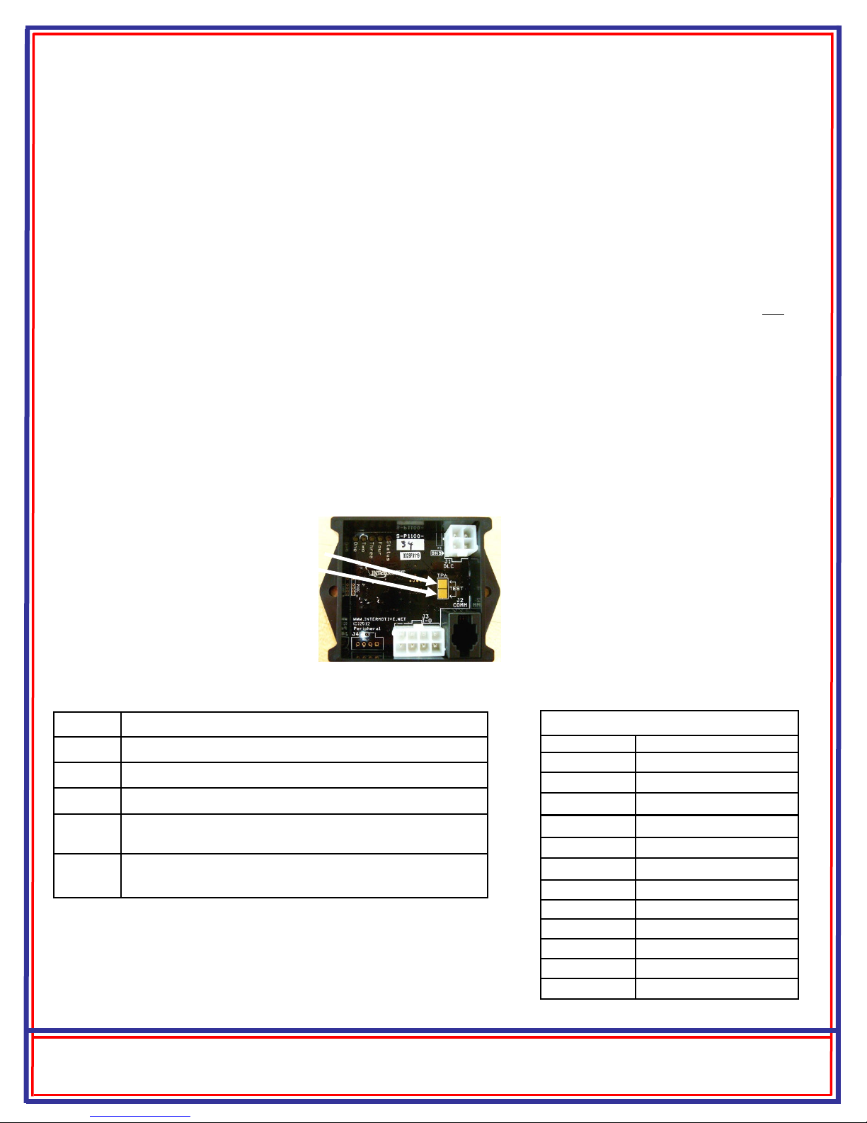
Diagnostics
Diagnostic mode is entered by
momentarily shorting the two gold
“Test” pads together on the module.
The module provides diagnostic LEDs
which illuminate according to the
following table. To exit this mode,
cycle the key or momentarily ground
the “Test” pad again.
L D # Diagnostic Mode L D Descriptions
1 On when fast idle is engaged
2 On when Green trigger wire is active
3 On when Gray RPM set wire is grounded
4 On when the Parking Brake is applied with the parking
brake trigger enabled
STATUS Continuously flashes two digit status codes. See Status
Code table

InterMotive Inc.
12840 Earhart Avenue
Auburn, CA 95602
Phone: (530) 823-1048
Fax: (530) 823-1516
Page 5 of 6
www.intermotive.net
AFIS422 SX-B-021318-OP
Leave in Vehicle
Operating Instructions AFIS422VSX-B Advanced Fast Idle System
Transit Application
2009-2017 Ford -Series, all engines
2009-2010 Ford F-250 - F-550, all engines
2014-2018 Ford F53/F59, 6.8L engine
2014-2016 Ford Transit Connect
2009-2017 Chevrolet xpress / GMC Savana
2015-2017 Chevrolet Silverado / Sierra
2011-2014 American General MV-1 4.6L
2016-2017 Isuzu NPR
Fast Idle Preconditions
The following preconditions must be met prior to initiating Fast Idle operation.
• ehicle speed zero
• Transmission in Park
• Accelerator pedal must not be applied
• Engine Coolant temperature must be less than 230ºF
• Engine RPM must be greater than 200 and less than 2800.
• Service Brake not applied
The following are options that are configurable at the factory for OEM customers. The default values are
shown.
System Operation
The Advanced Fast Idle System (AFIS) elevates engine idle speed in response to a number of triggers in order
to assist electrical or mechanical systems on the vehicle.
Fast Idle may be initiated by either a manual trigger (Green wire being grounded), a low battery voltage (low
BAT) condition, the A/C clutch engaging, or if enabled, by setting the Park Brake.
Fast Idle will only occur when the required preconditions are met, as listed below. Fast Idle operation will be
terminated by a loss of any of the preconditions, or removal of the trigger(s).
Fast Idle Triggers
Trigger Name Trigger Conditions Disable Conditions
Manual Engage Fast Idle Engage Green wire grounded
Or 12 input enabled (based on setting)
Fast Idle Engage Green wire not grounded
Or not 12 (based on setting)
BAT Low BAT < 12.5 Precondition iolation
A/C Boost A/C Clutch (engaged) Precondition iolation
Parking Brake Parking Brake applied Parking Brake Released
AFIS422VSX-B
Idle RPM: 1500 gas / 1200 Diesel
BAT Low: 12.5
A/C Trigger: Enabled
Parking Brake Trigger: Disabled
Submit product registration at www.intermotive.net
If the AFIS422 SX-B fails any step in the Post Installation Test, review the installation instructions and check all connections.
If necessary, call InterMotive Technical support at (530) 823-1048
AFIS422 SX-B-021318-CAD
Page 6 of 6
This manual suits for next models
2
Table of contents
Other InterMotive Control Unit manuals

Popular Control Unit manuals by other brands

Allmatic
Allmatic B1EE ERMES2 Manual for installation

SafeTrust
SafeTrust SABRE quick start guide

Pentair
Pentair E-Box SOLEO Connect Installation and operation guide

Wine Guardian
Wine Guardian Pro DP25 Installation, operation and maintenance manual

TFT
TFT Ball Intake Valve manual

Exodraft
Exodraft EFC15 instructions


