Sonoscape S2 User manual
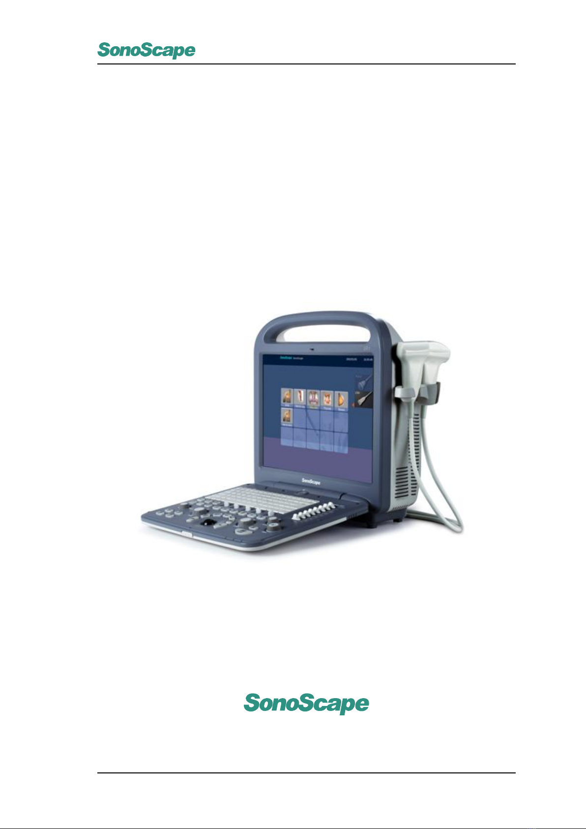
S2/S2BW
Digital Color Doppler Ultrasound System
S2/S2BW
Digital Color Doppler Ultrasound System
Basic Operator’s Manual
SonoScape Co., Ltd.
P/N: 4710.00149A01
0-1

S2/S2BW
Digital Color Doppler Ultrasound System
Regulatory Requirement
This product complies with regulatory requirements of the following European directive 93/42/EEC as amended
by 2007/47/EC concerning medical devices.
NOTE:
Some options are not available on some models!
This manual is subject to change without prior notice and without legal obligation attached!
P/N: 4710.00149A01
0-1

S2/S2BW
Digital Color Doppler Ultrasound System
Revision History
Revision Date Description
1.0 June 2012 First edition.
P/N: 4710.00149A01 Compiled on June, 2012.
P/N: 4710.00149A01
0-2

S2/S2BW
Digital Color Doppler Ultrasound System
Contents
1 Introduction 1-1
2 System Safety and Maintenance 2-1
2.1 Safety Overview . . . . . . . . . . . . . . . . . . . . . . . . . . . . . . . . . . . . . . . . 2-1
2.2 Symbol Used . . . . . . . . . . . . . . . . . . . . . . . . . . . . . . . . . . . . . . . . . . 2-2
2.3 Biological Safety . . . . . . . . . . . . . . . . . . . . . . . . . . . . . . . . . . . . . . . . 2-2
2.4 Adverse Effects and Precautions . . . . . . . . . . . . . . . . . . . . . . . . . . . . . . . 2-3
2.5 Scanning Patients and Education . . . . . . . . . . . . . . . . . . . . . . . . . . . . . . . 2-3
2.5.1 Safe Scanning Guideline . . . . . . . . . . . . . . . . . . . . . . . . . . . . . . . 2-3
2.5.2 Understanding the MI/TI Display . . . . . . . . . . . . . . . . . . . . . . . . . . . 2-5
2.6 Environmental Requirements . . . . . . . . . . . . . . . . . . . . . . . . . . . . . . . . . 2-7
2.7 Electrical Requirements . . . . . . . . . . . . . . . . . . . . . . . . . . . . . . . . . . . . 2-8
2.8 Electrical Safety . . . . . . . . . . . . . . . . . . . . . . . . . . . . . . . . . . . . . . . . 2-9
2.9 Transducer Maintenance . . . . . . . . . . . . . . . . . . . . . . . . . . . . . . . . . . . . 2-10
2.10 System Transportation . . . . . . . . . . . . . . . . . . . . . . . . . . . . . . . . . . . . . 2-13
2.10.1 Moving the System . . . . . . . . . . . . . . . . . . . . . . . . . . . . . . . . . . 2-13
2.10.2 Transporting the System . . . . . . . . . . . . . . . . . . . . . . . . . . . . . . . . 2-13
3 System Specifications 3-1
3.1 Product introduction . . . . . . . . . . . . . . . . . . . . . . . . . . . . . . . . . . . . . . 3-1
3.2 Base System . . . . . . . . . . . . . . . . . . . . . . . . . . . . . . . . . . . . . . . . . . 3-2
3.2.1 Front View . . . . . . . . . . . . . . . . . . . . . . . . . . . . . . . . . . . . . . . 3-2
3.2.2 Side View . . . . . . . . . . . . . . . . . . . . . . . . . . . . . . . . . . . . . . . 3-3
3.2.3 Rear View . . . . . . . . . . . . . . . . . . . . . . . . . . . . . . . . . . . . . . . 3-4
3.2.4 Keyboard Layout . . . . . . . . . . . . . . . . . . . . . . . . . . . . . . . . . . . . 3-5
3.2.5 Keyboard Description . . . . . . . . . . . . . . . . . . . . . . . . . . . . . . . . . 3-5
3.3 Probes and Accessories . . . . . . . . . . . . . . . . . . . . . . . . . . . . . . . . . . . . 3-8
3.4 Physical Specifications . . . . . . . . . . . . . . . . . . . . . . . . . . . . . . . . . . . . . 3-8
4 Starting the System 4-1
4.1 Probe Connection . . . . . . . . . . . . . . . . . . . . . . . . . . . . . . . . . . . . . . . 4-1
4.2 Power On and Off . . . . . . . . . . . . . . . . . . . . . . . . . . . . . . . . . . . . . . . 4-1
4.2.1 Using AC Supply . . . . . . . . . . . . . . . . . . . . . . . . . . . . . . . . . . . 4-1
4.2.2 Using Battery . . . . . . . . . . . . . . . . . . . . . . . . . . . . . . . . . . . . . 4-3
4.2.3 LED Indicators . . . . . . . . . . . . . . . . . . . . . . . . . . . . . . . . . . . . . 4-4
4.3 Patient Information . . . . . . . . . . . . . . . . . . . . . . . . . . . . . . . . . . . . . . . 4-5
4.3.1 Create New Patient . . . . . . . . . . . . . . . . . . . . . . . . . . . . . . . . . . 4-7
4.3.2 Patient Exam List . . . . . . . . . . . . . . . . . . . . . . . . . . . . . . . . . . . 4-16
4.3.3 DICOM Queue . . . . . . . . . . . . . . . . . . . . . . . . . . . . . . . . . . . . . 4-20
4.3.4 PPS Screen . . . . . . . . . . . . . . . . . . . . . . . . . . . . . . . . . . . . . . 4-21
4.3.5 Patient Exam Import/Export . . . . . . . . . . . . . . . . . . . . . . . . . . . . . . 4-21
4.4 Select Probes and Exam mode . . . . . . . . . . . . . . . . . . . . . . . . . . . . . . . . 4-24
P/N: 4710.00149A01
i

S2/S2BW
Digital Color Doppler Ultrasound System
4.5 Main User Interface . . . . . . . . . . . . . . . . . . . . . . . . . . . . . . . . . . . . . . 4-25
5 System Setup 5-1
5.1 General Setting . . . . . . . . . . . . . . . . . . . . . . . . . . . . . . . . . . . . . . . . 5-1
5.1.1 General . . . . . . . . . . . . . . . . . . . . . . . . . . . . . . . . . . . . . . . . 5-1
5.1.2 Display . . . . . . . . . . . . . . . . . . . . . . . . . . . . . . . . . . . . . . . . . 5-3
5.1.3 Menu . . . . . . . . . . . . . . . . . . . . . . . . . . . . . . . . . . . . . . . . . . 5-4
5.1.4 Storage . . . . . . . . . . . . . . . . . . . . . . . . . . . . . . . . . . . . . . . . 5-5
5.2 Peripheral . . . . . . . . . . . . . . . . . . . . . . . . . . . . . . . . . . . . . . . . . . . 5-6
5.3 Comment . . . . . . . . . . . . . . . . . . . . . . . . . . . . . . . . . . . . . . . . . . . . 5-7
5.4 Bodymark . . . . . . . . . . . . . . . . . . . . . . . . . . . . . . . . . . . . . . . . . . . 5-8
5.5 Measure . . . . . . . . . . . . . . . . . . . . . . . . . . . . . . . . . . . . . . . . . . . . 5-9
5.5.1 General . . . . . . . . . . . . . . . . . . . . . . . . . . . . . . . . . . . . . . . . 5-9
5.5.2 Menu . . . . . . . . . . . . . . . . . . . . . . . . . . . . . . . . . . . . . . . . . . 5-10
5.5.3 Formula . . . . . . . . . . . . . . . . . . . . . . . . . . . . . . . . . . . . . . . . 5-11
5.6 Report . . . . . . . . . . . . . . . . . . . . . . . . . . . . . . . . . . . . . . . . . . . . . 5-13
5.7 DICOM . . . . . . . . . . . . . . . . . . . . . . . . . . . . . . . . . . . . . . . . . . . . . 5-14
5.7.1 DICOM Image Storage . . . . . . . . . . . . . . . . . . . . . . . . . . . . . . . . 5-14
5.7.2 DICOM Storage Commitment . . . . . . . . . . . . . . . . . . . . . . . . . . . . . 5-15
5.7.3 DICOM Worklist . . . . . . . . . . . . . . . . . . . . . . . . . . . . . . . . . . . . 5-16
5.7.4 DICOM MPPS . . . . . . . . . . . . . . . . . . . . . . . . . . . . . . . . . . . . . 5-17
5.7.5 DICOM Print . . . . . . . . . . . . . . . . . . . . . . . . . . . . . . . . . . . . . . 5-18
5.8 System Information . . . . . . . . . . . . . . . . . . . . . . . . . . . . . . . . . . . . . . 5-20
6 B Mode 6-1
6.1 Entering B Mode . . . . . . . . . . . . . . . . . . . . . . . . . . . . . . . . . . . . . . . . 6-1
6.2 Parameter Adjustment . . . . . . . . . . . . . . . . . . . . . . . . . . . . . . . . . . . . . 6-1
6.2.1 Focal Number . . . . . . . . . . . . . . . . . . . . . . . . . . . . . . . . . . . . . 6-2
6.2.2 Focal Span . . . . . . . . . . . . . . . . . . . . . . . . . . . . . . . . . . . . . . 6-2
6.2.3 Chroma . . . . . . . . . . . . . . . . . . . . . . . . . . . . . . . . . . . . . . . . 6-3
6.2.4 Frequency (Freq) . . . . . . . . . . . . . . . . . . . . . . . . . . . . . . . . . . . 6-3
6.2.5 Line Density . . . . . . . . . . . . . . . . . . . . . . . . . . . . . . . . . . . . . . 6-3
6.2.6 SEC/Width . . . . . . . . . . . . . . . . . . . . . . . . . . . . . . . . . . . . . . . 6-4
6.2.7 Dynamic Range (DYN) . . . . . . . . . . . . . . . . . . . . . . . . . . . . . . . . 6-4
6.2.8 Gray Scale Curve (GSC) . . . . . . . . . . . . . . . . . . . . . . . . . . . . . . . 6-4
6.2.9 Persist . . . . . . . . . . . . . . . . . . . . . . . . . . . . . . . . . . . . . . . . . 6-5
6.2.10 µ-Scan . . . . . . . . . . . . . . . . . . . . . . . . . . . . . . . . . . . . . . . . . 6-5
6.2.11 Compound Imaging . . . . . . . . . . . . . . . . . . . . . . . . . . . . . . . . . . 6-5
6.2.12 Power . . . . . . . . . . . . . . . . . . . . . . . . . . . . . . . . . . . . . . . . . 6-6
6.2.13 Gain . . . . . . . . . . . . . . . . . . . . . . . . . . . . . . . . . . . . . . . . . . 6-6
6.2.14 Focus Position . . . . . . . . . . . . . . . . . . . . . . . . . . . . . . . . . . . . . 6-6
6.2.15 Depth . . . . . . . . . . . . . . . . . . . . . . . . . . . . . . . . . . . . . . . . . 6-7
6.2.16 Time Gain Compensation (TGC) . . . . . . . . . . . . . . . . . . . . . . . . . . . 6-7
6.3 Other B Mode Operations . . . . . . . . . . . . . . . . . . . . . . . . . . . . . . . . . . . 6-8
6.3.1 Freeze . . . . . . . . . . . . . . . . . . . . . . . . . . . . . . . . . . . . . . . . . 6-8
6.3.2 Image Orientation (Left/Right) . . . . . . . . . . . . . . . . . . . . . . . . . . . . . 6-8
6.3.3 Image Orientation (Up/Down) . . . . . . . . . . . . . . . . . . . . . . . . . . . . . 6-9
6.3.4 Dual- B Dispaly . . . . . . . . . . . . . . . . . . . . . . . . . . . . . . . . . . . . 6-9
6.3.5 Quad (4B) Display . . . . . . . . . . . . . . . . . . . . . . . . . . . . . . . . . . . 6-10
6.3.6 Tissue Harmonic Imaging (THI) . . . . . . . . . . . . . . . . . . . . . . . . . . . . 6-10
P/N: 4710.00149A01
ii

S2/S2BW
Digital Color Doppler Ultrasound System
7 CFM Mode 7-1
7.1 Enter CFM Mode . . . . . . . . . . . . . . . . . . . . . . . . . . . . . . . . . . . . . . . . 7-1
7.1.1 How to enter CFM . . . . . . . . . . . . . . . . . . . . . . . . . . . . . . . . . . . 7-1
7.2 Parameter Adjustment . . . . . . . . . . . . . . . . . . . . . . . . . . . . . . . . . . . . . 7-1
7.2.1 FREQUENCY . . . . . . . . . . . . . . . . . . . . . . . . . . . . . . . . . . . . . 7-2
7.2.2 Line Density . . . . . . . . . . . . . . . . . . . . . . . . . . . . . . . . . . . . . . 7-2
7.2.3 Wall Filter (WF) . . . . . . . . . . . . . . . . . . . . . . . . . . . . . . . . . . . . 7-2
7.2.4 B Reject . . . . . . . . . . . . . . . . . . . . . . . . . . . . . . . . . . . . . . . . 7-3
7.2.5 Color Map (C Map) . . . . . . . . . . . . . . . . . . . . . . . . . . . . . . . . . . 7-3
7.2.6 PERSIST . . . . . . . . . . . . . . . . . . . . . . . . . . . . . . . . . . . . . . . 7-3
7.2.7 POWER . . . . . . . . . . . . . . . . . . . . . . . . . . . . . . . . . . . . . . . . 7-4
7.2.8 D GAIN . . . . . . . . . . . . . . . . . . . . . . . . . . . . . . . . . . . . . . . . 7-4
7.2.9 PRF . . . . . . . . . . . . . . . . . . . . . . . . . . . . . . . . . . . . . . . . . . 7-4
7.2.10 STEER . . . . . . . . . . . . . . . . . . . . . . . . . . . . . . . . . . . . . . . . . 7-4
7.3 Other Operations . . . . . . . . . . . . . . . . . . . . . . . . . . . . . . . . . . . . . . . . 7-5
7.3.1 Freeze . . . . . . . . . . . . . . . . . . . . . . . . . . . . . . . . . . . . . . . . . 7-5
7.3.2 Single Image . . . . . . . . . . . . . . . . . . . . . . . . . . . . . . . . . . . . . . 7-5
7.3.3 Dual Display . . . . . . . . . . . . . . . . . . . . . . . . . . . . . . . . . . . . . . 7-5
7.3.4 Quad Display . . . . . . . . . . . . . . . . . . . . . . . . . . . . . . . . . . . . . 7-6
7.3.5 B+CFM Dual Dynamic . . . . . . . . . . . . . . . . . . . . . . . . . . . . . . . . . 7-7
8 DPI Mode 8-1
8.1 Entering DPI Mode . . . . . . . . . . . . . . . . . . . . . . . . . . . . . . . . . . . . . . . 8-1
8.2 Parameter Adjustment . . . . . . . . . . . . . . . . . . . . . . . . . . . . . . . . . . . . . 8-1
8.2.1 FREQUENCY . . . . . . . . . . . . . . . . . . . . . . . . . . . . . . . . . . . . . 8-2
8.2.2 Line Density . . . . . . . . . . . . . . . . . . . . . . . . . . . . . . . . . . . . . . 8-2
8.2.3 Wall Filter . . . . . . . . . . . . . . . . . . . . . . . . . . . . . . . . . . . . . . . 8-2
8.2.4 B Reject . . . . . . . . . . . . . . . . . . . . . . . . . . . . . . . . . . . . . . . . 8-2
8.2.5 C Map/DIRECT.D . . . . . . . . . . . . . . . . . . . . . . . . . . . . . . . . . . . 8-2
8.2.6 PERSIST . . . . . . . . . . . . . . . . . . . . . . . . . . . . . . . . . . . . . . . 8-2
8.2.7 POWER . . . . . . . . . . . . . . . . . . . . . . . . . . . . . . . . . . . . . . . . 8-2
8.2.8 D GAIN . . . . . . . . . . . . . . . . . . . . . . . . . . . . . . . . . . . . . . . . 8-3
8.3 Other Operations . . . . . . . . . . . . . . . . . . . . . . . . . . . . . . . . . . . . . . . . 8-3
9 M Mode 9-1
9.1 Starting M Mode . . . . . . . . . . . . . . . . . . . . . . . . . . . . . . . . . . . . . . . . 9-1
9.1.1 Pre-active Mode . . . . . . . . . . . . . . . . . . . . . . . . . . . . . . . . . . . . 9-1
9.1.2 Active Mode . . . . . . . . . . . . . . . . . . . . . . . . . . . . . . . . . . . . . . 9-1
9.2 Parameter Adjustment . . . . . . . . . . . . . . . . . . . . . . . . . . . . . . . . . . . . . 9-2
9.2.1 Sweep Speed . . . . . . . . . . . . . . . . . . . . . . . . . . . . . . . . . . . . . 9-2
9.2.2 Display Format . . . . . . . . . . . . . . . . . . . . . . . . . . . . . . . . . . . . 9-2
9.2.3 Chroma . . . . . . . . . . . . . . . . . . . . . . . . . . . . . . . . . . . . . . . . 9-3
9.2.4 Smooth(SMO) . . . . . . . . . . . . . . . . . . . . . . . . . . . . . . . . . . . . . 9-3
9.3 Other Operations . . . . . . . . . . . . . . . . . . . . . . . . . . . . . . . . . . . . . . . . 9-3
9.3.1 Freeze . . . . . . . . . . . . . . . . . . . . . . . . . . . . . . . . . . . . . . . . . 9-3
9.3.2 Adjust M Mode Sampling Line . . . . . . . . . . . . . . . . . . . . . . . . . . . . . 9-4
9.3.3 Dual Display . . . . . . . . . . . . . . . . . . . . . . . . . . . . . . . . . . . . . 9-4
10 PW Mode 10-1
10.1 Entering PW Mode . . . . . . . . . . . . . . . . . . . . . . . . . . . . . . . . . . . . . . . 10-1
10.1.1 Pre-Active Mode . . . . . . . . . . . . . . . . . . . . . . . . . . . . . . . . . . . . 10-1
P/N: 4710.00149A01
iii

S2/S2BW
Digital Color Doppler Ultrasound System
10.1.2 Active Mode . . . . . . . . . . . . . . . . . . . . . . . . . . . . . . . . . . . . . . 10-1
10.2 Parameter Adjustment . . . . . . . . . . . . . . . . . . . . . . . . . . . . . . . . . . . . . 10-2
10.2.1 PW FREQUENCY . . . . . . . . . . . . . . . . . . . . . . . . . . . . . . . . . . . 10-3
10.2.2 Sweep Speed . . . . . . . . . . . . . . . . . . . . . . . . . . . . . . . . . . . . . 10-3
10.2.3 Dynamic Range(DYN) . . . . . . . . . . . . . . . . . . . . . . . . . . . . . . . . . 10-3
10.2.4 Wall Filter(WF) . . . . . . . . . . . . . . . . . . . . . . . . . . . . . . . . . . . . . 10-3
10.2.5 CHROMA . . . . . . . . . . . . . . . . . . . . . . . . . . . . . . . . . . . . . . . 10-3
10.2.6 DISPLAY FORMAT . . . . . . . . . . . . . . . . . . . . . . . . . . . . . . . . . . 10-3
10.2.7 POWER . . . . . . . . . . . . . . . . . . . . . . . . . . . . . . . . . . . . . . . . 10-3
10.2.8 Baseline . . . . . . . . . . . . . . . . . . . . . . . . . . . . . . . . . . . . . . . . 10-3
10.3 B + PW Other Operations . . . . . . . . . . . . . . . . . . . . . . . . . . . . . . . . . . . 10-4
10.3.1 Freeze . . . . . . . . . . . . . . . . . . . . . . . . . . . . . . . . . . . . . . . . . 10-4
10.3.2 Adjust PW Sampling Line . . . . . . . . . . . . . . . . . . . . . . . . . . . . . . . 10-4
10.3.3 Adjust PW Sample Volume . . . . . . . . . . . . . . . . . . . . . . . . . . . . . . 10-5
10.3.4 Adjust PW Sample Angle . . . . . . . . . . . . . . . . . . . . . . . . . . . . . . . 10-5
10.3.5 Adjust Baseline . . . . . . . . . . . . . . . . . . . . . . . . . . . . . . . . . . . . 10-5
10.3.6 Dual Display . . . . . . . . . . . . . . . . . . . . . . . . . . . . . . . . . . . . . . 10-5
11 CW Mode 11-1
12 Miscellaneous Functions 12-1
12.1 Annotation . . . . . . . . . . . . . . . . . . . . . . . . . . . . . . . . . . . . . . . . . . . 12-1
12.1.1 Textual Annotation . . . . . . . . . . . . . . . . . . . . . . . . . . . . . . . . . . . 12-1
12.1.2 Arrow . . . . . . . . . . . . . . . . . . . . . . . . . . . . . . . . . . . . . . . . . 12-2
12.2 Bodymark . . . . . . . . . . . . . . . . . . . . . . . . . . . . . . . . . . . . . . . . . . . 12-2
12.3 Save and Review . . . . . . . . . . . . . . . . . . . . . . . . . . . . . . . . . . . . . . . . 12-4
12.4 Customize Exam Mode . . . . . . . . . . . . . . . . . . . . . . . . . . . . . . . . . . . . 12-6
12.4.1 Create New Exam Mode . . . . . . . . . . . . . . . . . . . . . . . . . . . . . . . 12-7
12.4.2 Exam Mode Management . . . . . . . . . . . . . . . . . . . . . . . . . . . . . . . 12-8
12.4.3 Exam Mode Import and Export . . . . . . . . . . . . . . . . . . . . . . . . . . . . 12-9
12.5 Print . . . . . . . . . . . . . . . . . . . . . . . . . . . . . . . . . . . . . . . . . . . . . . 12-10
13 Transducers 13-1
13.1 Transducer Information . . . . . . . . . . . . . . . . . . . . . . . . . . . . . . . . . . . . . 13-1
13.1.1 Supported Transducers . . . . . . . . . . . . . . . . . . . . . . . . . . . . . . . . 13-1
13.1.2 Acoustic Output . . . . . . . . . . . . . . . . . . . . . . . . . . . . . . . . . . . . 13-1
13.2 Environmental Requirements . . . . . . . . . . . . . . . . . . . . . . . . . . . . . . . . . 13-1
13.3 Preparation and Usage of the Probe . . . . . . . . . . . . . . . . . . . . . . . . . . . . . . 13-2
13.3.1 Inspection . . . . . . . . . . . . . . . . . . . . . . . . . . . . . . . . . . . . . . . 13-2
13.3.2 Probe Connection . . . . . . . . . . . . . . . . . . . . . . . . . . . . . . . . . . . 13-2
13.3.3 Preparation for Scanning . . . . . . . . . . . . . . . . . . . . . . . . . . . . . . . 13-2
13.3.4 Scanning . . . . . . . . . . . . . . . . . . . . . . . . . . . . . . . . . . . . . . . . 13-3
13.4 Probe Maintenance: Cleaning and Disinfection . . . . . . . . . . . . . . . . . . . . . . . . 13-3
13.4.1 Probe immersion level . . . . . . . . . . . . . . . . . . . . . . . . . . . . . . . . . 13-3
13.4.2 Cleaning Instructions . . . . . . . . . . . . . . . . . . . . . . . . . . . . . . . . . 13-4
13.4.3 Disinfection Instructions . . . . . . . . . . . . . . . . . . . . . . . . . . . . . . . . 13-4
14 System Maintenance 14-1
14.1 Guidance for Service . . . . . . . . . . . . . . . . . . . . . . . . . . . . . . . . . . . . . . 14-1
14.2 Manufacturer Responsibility . . . . . . . . . . . . . . . . . . . . . . . . . . . . . . . . . . 14-1
14.3 Contact Information . . . . . . . . . . . . . . . . . . . . . . . . . . . . . . . . . . . . . . 14-1
P/N: 4710.00149A01
iv


S2/S2BW
Digital Color Doppler Ultrasound System
P/N: 4710.00149A01
vi

S2/S2BW
Digital Color Doppler Ultrasound System
Chapter 1
Introduction
S2/S2BW is a full digital color Doppler ultrasound system for general application.
The high performances of the SonoScape S2 series stem from the advanced ultrasound doppler imaging
technologies that include full digital beam-former, wide dynamic range, multi-beam processing, etc. The
ergonomic user-friendly design enables user to customize the system according to the specific application,
and the graphic exam icon assure you familiar with the system in few minutes.
Applications:
This general-purpose ultrasonic imaging instrument is intended for use by a qualified physician for evaluation
of Fetal, Abdominal, Pediatric, Small Organ(breast, testes, thyroid), Trans-rectal, Trans-vaginal, Peripheral
Vascular, Musculoskeletal (Conventional and Superficial), Cardiac(neonatal and adult), OB/Gyn and Urology.
Contraindication:
Can not be used for eye examinations or any other exam which may cause the acoustic beam pass
through eye.
P/N: 4710.00149A01
1-1

S2/S2BW
Digital Color Doppler Ultrasound System
P/N: 4710.00149A01
1-2

S2/S2BW
Digital Color Doppler Ultrasound System
Chapter 2
System Safety and Maintenance
2.1 Safety Overview
This section discusses measures to ensure the safety of both the operator and patient.
To ensure the safety of both operator and patient, please read the relevant details in this chapter carefully
before operating this system. Disregarding the WARNINGS or violation of relevant rules may result in personal
injury or even loss of life for operator or patient.
Users should observe the following PRECAUTIONS:
•This system complies with Type BF general equipment, and the EN60601-1 standard.
•
Do not modify this system in any way. Necessary modifications must be made only by the manufacturer
or its designated agents.
•This system has been fully adjusted at the factory. Do not adjust any fixed adjustable parts.
•
In the event of a malfunction, turn off the system immediately and inform the manufacturer or its
designated agents.
•
The power cable of the system should only be connected to a grounded power socket. Do not remove
the ground cable for any reason.
•
Only connect this system, either electronically or mechanically, with devices that comply with the
EN60601-1 standard. Recheck the leakage current and other safety performance indices of the entire
system to avoid potential system damage caused by leakage from a current superposition.
•
The system does not incorporate any specialized protective measures in the event it is configured with
high-frequency operation devices. The operator should use CAUTION in these types of applications.
•
The system should be installed only by personnel authorized by the manufacturer. Do not attempt to
install the system yourself.
•Only an authorized service engineer may perform maintenance.
•Only a qualified operator, or someone under qualified supervision, should use the system.
•Do not use this system in the presence of flammable substances or an explosion may occur.
•
Do not continuously scan the same part of a patient or expose the patient to prolonged scanning. Doing
so may harm the patient.
•
When using the system for ultrasound testing, use only qualified ultrasound gel that complies with
system standards.
P/N: 4710.00149A01
2-1

S2/S2BW
Digital Color Doppler Ultrasound System
•
Do not use the switch at the back of the unit for normal shut down. Always use the power-on button in
the keyboard area
•
Do not unplug probe when the system is in active operation. Doing so may damage the probe. Always
go to EXAM screen when need to remove the probe.
•
To prevent from arm or neck injury, the operator should not stay at the same position for too long during
patient scanning without taking break.
•Do not put liquid on top of the main unit.
•For proper disposal of this product, please contact our service department.
2.2 Symbol Used
Refer to Appendix A.
2.3 Biological Safety
This product, as with all diagnostic ultrasound equipment, should be used only for valid reasons and should
be used both for the shortest period of time and at the lowest power settings necessary (
ALARA
- As Low
As Reasonably Achievable) to produce diagnostically acceptable images.
The AIUM offers the following guidelines:
Clinical Safety Quoted from AIUM
Approved March 26, 1997
Diagnostic ultrasound has been in use since the late 1950s. Given its known benefits and
recognized efficacy for medical diagnosis, including use during human pregnancy, the American
Institute of Ultrasound in Medicine herein addresses the clinical safety of such use:
There are no confirmed biological effects on patients or instrument operators caused by
exposures from present diagnostic ultrasound instruments. Although the possibility exists that
such biological effects may be identified in the future, current data indicate that the benefits
to patients of the prudent use of diagnostic ultrasound outweigh the risks, if any that may be
present.
Heating:
Elevating tissue temperature during obstetrical examinations creates medical concerns. At the embryo
development stage, the rise in temperature and the length of time exposed to heat combine to determine
potential detrimental effects. Exercise CAUTION particularly during Doppler/Color exams.
The Thermal Index (TI) provides a statistical estimate of the potential temperature elevation (in centigrade) of
tissue temperature. Three forms of TI are available: TIS, for soft tissue exposures; TIB, for instances when
bone lies near the beam focus; and TIC, for the heating of bone situated close to the transducer.
Cavitation:
Cavitation may occur when sound passes through an area that contains a cavity, such as a gas bubble or air
pocket (in the lung or intestine, for example). During the process of cavitation, the sound wave may cause the
bubble to contract or resonate. This oscillation may cause the bubbles to explode and damage the tissue. The
Mechanical Index (MI) has been created to help users accurately evaluate the likelihood of cavitation and the
related adverse effects.
P/N: 4710.00149A01
2-2

S2/S2BW
Digital Color Doppler Ultrasound System
2.4 Adverse Effects and Precautions
This ultrasound system, same as all other diagnostic ultrasound system in the market, should be used only
for clinically appropriate reasons, for the shorteds period of time and at power settings as low as reasonably
achievable (ALARA).
The American Institute of Ultrasound in Medicine (AIUM) principle of As Low As Reasonably Achievable
(ALARA) is recommended during selection of the output of ultrasound power. Try not to aim probe at the
smae spot in tissue for a long period of time unless it is necessary for diagnostic purpose.
This system, as a basic imaging system with the Doppler and Color Doppler feature generates acoustic power
that is below pre-enactment levels, which are generally considered to be safe for the respective applications.
2.5 Scanning Patients and Education
The Track-3 or IEC60601-2-37 output display standard allows users to share the responsibility for the safe
use of this ultrasound system. Follow these usage guidelines for safe operation:
•In order to maintain proper cleanliness of the transducers, always clean them between patients.
•Always use a new disinfected sheath on all EV/ER probes during every exam.
•
Continuously move the probe, rather than staying in a single spot, to avoid elevated temperatures in
one part of the patient’s body.
•Move probe away from the patient when not actively scanning.
•
Understand the meaning of the TI, TIS, TIB, TIC, and MI output display, as well as the relationship
between these parameters and the thermal/cavitation bioeffect to the tissue.
•
Expose the patient to only the very lowest practical transmit power levels for the shortest possible time
to achieve a satisfactory diagnosis (ALARA - As Low As Reasonably Achievable).
2.5.1 Safe Scanning Guideline
1. Ultrasound should only be used for medical diagnosis and only by trained medical personnel.
2.
Diagnostic ultrasound procedures should be done only by personnel fully trained in the use of the
equipment, in the interpretation of the results and images, and in the safe use of ultrasound (including
education as to potential hazards).
3.
Operators should understand the likely influence of the machine controls, the operating mode (e.g.
B-mode, color Doppler imaging or spectral Doppler) and probe frequency on thermal and cavitation
hazards.
4.
Select a low setting for each new patient. Output should only be increased during the examination if
penetration is still required to achieve a satisfactory result, and after the Gain control has been moved
to its maximum value.
5. Maintain the shortest examination time necessary to produce a useful diagnostic result.
6.
Do not hold the probe in a fixed position for any longer than is necessary. It should be removed from
the patient whenever there is no need for real-time imaging or spectral Doppler acquisition. The freeze
frame and Cine loop capabilities allow images to be reviewed and discussed without exposing the
patient to continuous scanning.
P/N: 4710.00149A01
2-3

S2/S2BW
Digital Color Doppler Ultrasound System
7.
Do not use endo-cavity probes if there is noticeable self heating of the probe when operating in the air.
Although applicable to any probe, take particular care during trans-vaginal exams during the first eight
weeks of gestation.
8.
Take particular care to reduce output and minimize exposure time of an embryo or fetus when the
temperature of the mother is already elevated.
9. Take particular care to reduce the risk of thermal hazard during diagnostic ultrasound when exposing:
an embryo less than eight weeks after gestation; or the head, brain or spine of any fetus or neonate.
10.
Operators should continually monitor the on-screen thermal index (TI) and mechanical index (MI) values
and use control settings that keep these settings as low as possible while still achieving diagnostically
useful results.
In obstetric examinations, TIS (soft tissue thermal index) should be monitored during scans carried out
in the first eight weeks after gestation, and TIB (bone thermal index) thereafter. In applications where
the probe is very close to bone (e.g. trans-cranial applications), TIC (cranial thermal index) should be
monitored.
MI> 0.3
There is a possibility of minor damage to neonatal lung
or intestine. If such exposure is necessary, reduce the
exposure time as much as possible.
MI> 0.7
There is a risk of cavitation if an ultrasound contrast
agent containing gas micro-spheres is being used.
There is a theoretical risk of cavitation without the pres-
ence of ultrasound contrast agents. The risk increases
with MI values above this threshold.
TI> 0.7
The overall exposure time of an embryo or fetus should
be restricted in accordance with Table 2.1 below as a
reference.
TI Maximum exposure time (minutes)
0.7 60
1.0 30
1.5 15
2.0 4
2.5 1
Table 2.1: Maximum recommended exposure times for an embryo or fetus
11.
Non-diagnostic use of ultrasound equipment is not generally recommended. Examples of non-diagnostic
uses of ultrasound equipment include repeated scans for operator training, equipment demonstration
using normal subjects, and the production of souvenir pictures or videos of a fetus.
For equipment of which the safety indices are displayed over their full range of values, the TI should
always be less than 0.5 and the MI should always be less than 0.3. Avoid frequent repeated exposure
of any subject.
Scans in the first trimester of pregnancy should not be carried out for the sole purpose of producing
souvenir videos or photographs, nor should their production involve increasing the exposure levels or
extending the scan times beyond those needed for clinical purposes.
12.
Diagnostic ultrasound has the potential for both false positive and false negative results. Misdiagnosis
is far more dangerous than any effect that might result from the ultrasound exposure. Therefore,
diagnostic ultrasound should be performed only by those with sufficient training and education.
P/N: 4710.00149A01
2-4

S2/S2BW
Digital Color Doppler Ultrasound System
2.5.1.1 Temperature Display for Transducers Intended for Internal Use
For transducers intended for internal applications, e.g. the intracavitary transducers, the transducer tip
temperature is displayed on the screen.To protect the patient against the harm of excessive temperature, the
system automatically turns off the transducer when the temperature of the transducer reaches a threshold
temperature.
2.5.2 Understanding the MI/TI Display
Track-3 follows the Output Display Standard for systems which include fetal Doppler applications. The acoustic
output will not be evaluated on an application-specific basis, but the global maximum de-rated Ispta must
be
≤
720 mW/cm2 and either the global maximum MI must be
≤
1.9 or the global maximum de-rated Isppa
must be
≤
190 W/cm2. An exception is for ophthalmic use, in which case the TI=max (TIS_as, TIC) is not to
exceed 1.0; Ispta.3
≤
50mW/cm2, and MI
≤
0.23. Track-3 gives the user the freedom to increase the output
acoustic power for a specific exam, and still limit output acoustic power within the global maximum de-rated
Ispta ≤720 mW/cm2 under an Output Display Standard.
For any diagnostic ultrasonic systems, Track-3 provides an Output Indices Display Standard. The diagnostic
ultrasound systems and its operator’s manual contain the information regarding an ALARA (As Low As
Reasonably Achievable) education program for the clinical end-user and the acoustic output indices, MI and
TI.
The MI describes the likelihood of cavitation, and the TI offers the predicted maximum temperature rise in
tissue as a result of the diagnostic examination.
In general, a temperature increase of 2.5oC must be present consistently at one spot for 2 hours to cause
fetal abnormalities. Avoiding a local temperature rise above 1oC should ensure that no thermally induced
biologic effect occurs.
When referring to the TI for potential thermal effect, a TI equal to 1 does not mean the temperature will rise
1 degree C. It only means an increased potential for thermal effects can be expected as the TI increases.
A high index does not mean that bioeffects are occurring, but only that the potential exists and there is no
consideration in the TI for the scan duration, so minimizing the overall scan time will reduce the potential for
effects. These operator control and display features shift the safety responsibility from the manufacturer to the
user. So it is very important to have the Ultrasound systems display the acoustic output indices correctly and
the education of the user to interpret the value appropriately.
RF: De-rating factor
In Situ intensity and pressure cannot currently be measured. Therefore, the acoustic power measurement is
normally done in the water tank, and when soft tissue replaces water along the ultrasound path, a decrease in
intensity is expected. The fractional reduction in intensity caused by attenuation is DENOTED by the de-rating
factor RF,
RF=(−.a·f·z)
Where a is the attenuation coefficient in dB cm-1 MHz-1, f is the transducer center frequency, and z is the
distance along the beam axis between the source and the point of interest.
De-rating factor RF for the various distances and frequencies with attenuation coefficient 0.3dB cm-1 MHz-1
in homogeneous soft tissue is listed in the following table. An example is if the user uses 7.5MHz frequency,
the power will be attenuated by .0750 at 5cm, or 0.3x7.5x5=-11.25dB. The De-rated Intensity is also referred
to as ’.3’ at the end (e.g. Ispta.3).
P/N: 4710.00149A01
2-5

S2/S2BW
Digital Color Doppler Ultrasound System
Distance Frequency (MHz)
(cm) 1 3 5 7,5
1 0,9332 0,8128 0,7080 0,5957
2 0,8710 0,6607 0,5012 0,3548
3 0,8128 0,5370 0,3548 0,2113
4 0,7586 0,4365 0,2512 0,1259
5 0,7080 0,3548 0,1778 0,0750
6 0,6607 0,2884 0,1259 0,0447
7 0,6166 0,2344 0,0891 0,0266
8 0,5754 0,1903 0,0631 0,0158
I’=I*RF Where I’ is the intensity in soft tissue, I is the time-averaged
intensity measured in water.
Tissue Model
Tissue temperature elevation depends on power, tissue type, beam width, and scanning mode. Six models
are developed to mimic possible clinical situations.
Thermal Mod-
els
Composition Mode Specification Typ. app
1TIS Soft tissue Unscanned Large aperture (>1cm) Liver PW
2TIS Soft tissue Unscanned Small aperture (<1cm) Pencil probe
3TIS Soft tissue Scanned Evaluated at surface Breast color
4TIB
Soft tissue and bone
Scanned Soft tissue at surface Muscle color
5TIB
Soft tissue and bone
Unscanned Bone at focus Fetus head PW
6TIC
Soft tissue and bone
Unscanned / Scanned Bone at surface Trans cranial
Soft tissue
Describes low fat content tissue that does not contain calcifications or large gas-filled spaces.
Scanned: (auto-scan)
Refers to the steering of successive burst through the field of view, e.g. B and color mode.
UnScanned
Emission of ultrasonic pulses occurs along a single line of sight and is unchanged until the transducer is
moved to a new position. For instance, the PW, CW and M mode.
TI
TI is defined as the ratio of the In Situ acoustic power (W.3) to the acoustic power required to raise tissue
temperature by 1oC (Wdeg),
T I =W./W deg
Three TIs corresponding to soft tissue (TIS) for abdominal; bone (TIB) for fetal and neonatal cephalic; and
cranial bone (TIC) for pediatric and adult cephalic, have been developed for applications in different exams.
An estimate of the acoustic power in milliwatts necessary to produce a 1
°C
temperature elevation in soft tissue
is:
W deg =/ f c
for model 1 to 4, where fc is the center frequency in MHz.
W deg = ·K·D
for model 5 and 6, where K (beam shape factor) is 1.0, D is the aperture diameter in cm at the depth of
interest
MI
Cavitation is more likely to occur at high pressures and low frequencies in pulse ultrasound wave in the tissue,
which contains the bubble or air pocket (for instance, the lung, intestine, or scan with gas contrast agents).
P/N: 4710.00149A01
2-6

S2/S2BW
Digital Color Doppler Ultrasound System
The threshold under optimum conditions of pulsed ultrasound is predicted by the ratio of the peak pressure to
the square root of the frequency.
MI =Pr 0/pf c
Pr’ is the de-rated (0.3) peak rare-fractional pressure in Mpa at the point where PII is the maximum, and fc
is the center frequency in MHz. PII is the Pulse Intensity Integral that the total energy per unit area carried
by the wave during the time duration of the pulse.
The peak rare-fractional pressure is measured in hydrophone maximum negative voltage normalized by
the hydrophone calibration parameter.
Display Guideline
For different operation modes, different indices must be displayed. However, only one index needs to be
shown at a time. Display is not required if maximum MI is less than 1.0 for any setting of the operating mode,
or if maximum TI is less than 1.0 for any setting of the operating mode. For TI, if the TIS and TIC are both
greater than 1.0, the scanners need not be capable of displaying both indices simultaneously. If the index falls
below 0.4, no display is needed. The display increments are no greater than 0.2 for index value less than one
and no greater than 1.0 for index values greater than one (e.g. 0.4, 0.6, 0.8, 1, 2, 3).
Display and Report in Different Mode
For B-Scan Mode
Only display and report MI, and start from 0.4 if maximum MI > 1.0
For Color Mode
Only display and report TIS or TIB and start from 0.4 if maximum TI > 1.0
For Doppler Mode
Only display and report TIS or TIB and start from 0.4 if maximum TI > 1.0
Below is a simple guideline for the user when TI exceeds one limit exposure time to 4(6-TI) minutes based on
the National Council on Radiation Protection. Exposure Criteria for Medical Diagnostic Ultrasound: I. Criteria
Based on Thermal Mechanisms. Report No.113 1992:
Operator Control Features
The user should be aware that certain operator controls may affect the acoustic output. It is recommended
to use the default (or lowest) output power setting and compensate using Gain control to acquire an image.
Other than the output power setting in the soft-menu, which has the most direct impact on the power; the
PRF, image sector size, frame rate, depth, and focal position also slightly affect the output power. The default
setting is normally around 70% of the allowable power depending on the exam icon.
2.6 Environmental Requirements
The environmental requirements for using the ultrasound system are listed below.
Operation
Temperature: 10°C ∼40°C
Relative Humidity: 30%∼75%, no condensation
Atmospheric Pressure: 700∼1060hPa
Transport & Storage
Temperature: -20°C ∼55°C
Relative Humidity: 20% ∼90 %, no condensation
Atmospheric Pressure: 700∼1060hPa
Strong radiation sources or powerful electromagnetic waves (e.g. electromagnetic waves from radio broad-
casting) may result in image ghosting or noise. The system should be isolated from such radiation sources or
P/N: 4710.00149A01
2-7
S2/S2BW
Digital Color Doppler Ultrasound System
electromagnetic waves.
2.7 Electrical Requirements
110∼240 V AC, 2.7-1.2A, 50/60Hz
Main unit voltage
Maintain a fluctuation range of less than ±10% or the system may be damaged.
Grounding
Before connecting the power cable, connect the accompanying earth protection cable to a
specialized grounding device.
Note:
•
Please ensure that the power requirements are satisfied. Only use power lines that
meet the system guidelines—failure to follow these procedures may result in system
damage.
Caution for using AC adapter:
• Use the AC adapter approved by SonoScape only.
• AC adapter can get very hot if being used in poorly ventilated area. Maintain good ventila-
tion for heat dissipation. Do not put any items on the AC adapter or the power cable.
• Make sure that the power cable is not entangled and avoid step on the cable.
• Do not the adapter in its carrying case.
• To ensure proper grounding, connect the AC adapter to a receptacle/outlet marked with
“hospital grade”.
Caution for using battery:
• To assure the best performance of the system, we recommend to replace the battery pack
every three years.
• This battery is designed to be an integral part of the ultrasound system. Attempting do-it-
yourself removal of the battery not only voids the warranty but also violates the regulations,
and is discouraged by IEC 60601-1.
• Do not short the conductive parts of the battery.
• The temperature of the battery can be high right after discharging completes. To protect it
from overheat damage, it will not be charged immediately after being connected to an AC
supply.
• During long time storage of the battery, a discharge-charge cycle should be performed in
every 3 to 6 months.
• Do not discard the battery in fire.
• Do not remove the battery pack from the system.
• Do not put foreign metal or other conductive parts inside the system to avoid electrical short.
• Protect the battery from rain and do not immerse the battery in water.
• Do not place the system at unstable position and use the system.
• Do not heat or burn the battery.
• Do not use the system near any source which produces significant amount of heat, such as
fire and heater.
• Do not charge or discharge the battery in direct sunlight.
• Do not destroy or disassemble the battery; Do not solder the battery.
• This battery pack should only be used with the ultrasound system which it has been designed
for.
• Do not use the battery in strong electric field.
For more information about the AC adapter and the battery, read Section 4.2.
P/N: 4710.00149A01
2-8

S2/S2BW
Digital Color Doppler Ultrasound System
2.8 Electrical Safety
Only trained health professionals should operate this system. This equipment complies with the following
standards:
•The equipment conforms with the following regulations for electrical safety,
–
IEC 60601-1, Medical electrical equipment Part 1: General requirements for basic safety and
essential performance, Class I, BF, continuous operation
–
IEC 60601-2-37, Medical Electrical Equipment Part 2-37: Particular Requirements for the Basic
Safety and Essential Performance of Ultrasonic Medical Diagnostic and Monitoring Equipment
•The equipment conforms with the following EMC/EMI standards: IEC60601-1-2, Class A (CE)
•Degrees of protection against harmful liquid:
For the main
system:
IPX0
For the transducer:
IPX7, from the acoustic window to the junction line (
Fig-
ure 13.1);
and IPX1 for other parts that may contact with the pa-
tient, excluding the transducer connector.
For maximum safety, adhere to these guidelines:
• Proper grounding of the system is critical to avoid electrical shock. For protection, ground the
system with a three-conductor cable, and plug the system into a hospital-grade receptacle
or outlet.
• Do not remove or entangle the grounding wire.
• Do not remove the protective covers of the system. These covers protect users from hazardous
voltages. Only authorized service technicians can make replacements of the parts inside the
system.
• Never use this system while inflammable gas is present!
• Devices must be powered from a receptacle marked “hospital grade” before being con-
nected to the system directly. In case “hospital grade” receptacles are not available, use
isolation transformers instead.
Use of foot switch:
The foot switch paddle must not be used in the operating room.
Take the following precautions when an optional printer is connected to your ultrasound system:
1. When the ultrasound system and the optional printer are connected to the mains outlets, the
outlets must have the protective grounding conductor.
2. The accessories provided with the ultrasound system are safe to operate in patient environ-
ment. Other accessories or devices not listed in the supported accessories’ list (Contact the
manufacturer for the updated and complete list of accessories.) must not be used.
3. Installation of the system must be performed by the service engineer authorized by SonoScape.
P/N: 4710.00149A01
2-9
Other manuals for S2
2
This manual suits for next models
1
Table of contents
Popular Industrial Equipment manuals by other brands


Metcalfe
Metcalfe GU4 Installation & operating instructions

Balluff
Balluff BTL6-A/E500/B50 M E2/E28-KA LA Series Condensed guide

Magnaflux
Magnaflux Universal WE TOUCH with TCODE operating manual

SICK
SICK SIM800 operating instructions

ABB
ABB TPS52-F33 Operation manual

Dustcontrol
Dustcontrol RAF 2501 Original instructions