Sony hcd-gn1000d User manual

HCD-GN1000D
E Model
SERVICE MANUAL
MINI HI-FI COMPONENT SYSTEM
Sony Corporation
Home Audio Division
Published by SonyTechno Create Corporation
9-887-254-01
2006E02-1
© 2006.05
SPECIFICATIONS
Ver.1.0 2006.05
– Continued on next page –
•HCD-GN1000D is the Amplifier,
DVD player, tape deck and tuner
section in MHC-GN1000D.
DVD Model Name Using Similar Mechanism HCD-GNV111D
DVD Mechanism Type CDM74HF-DVBU101
Section Optical Pick-up Name KHM-310CAB/C2NP
TAPE Model Name Using Similar Mechanism NEW
Section Tape Transport Mechanism Type CWN42RR603
Amplifier section
The following are measured at AC 120, 127, 220,
240V 50/60 Hz
DIN power output (rated): 125 W + 125 W
(6 ohms at 1 kHz, DIN)
Continuous RMS power output (reference)
Front speaker: 170 W + 170 W
(6 ohms at 1 kHz, 10%
THD)
Center speaker: 70 W
(6 ohms at 1 kHz, 10%
THD)
Surround speaker: 70 W + 70 W
(6 ohms at 1 kHz, 10%
THD)
Subwoofer: 210 W (8 ohms at 100 Hz,
10% THD)
Inputs
VIDEO INPUT (phono jacks): VIDEO: 1 Vp-p, 75 ohms
AUDIO L/R: Voltage
250 mV, impedance 47
kilohms
TV/SATAUDIO IN L/R (phono jacks):
Voltage 250 mV/450 mV,
impedance 47 kilohms
MIC 1 or 2 (phone jack): Sensitivity 1 mV,
impedance 10 kilohms
Outputs
AUDIO OUT (phono jacks): Voltage 250 mV,
impedance 1 kilohm
VIDEO OUT (phono jack): Max. output level 1 Vp-p,
unbalanced, Sync.
negative load impedance
75 ohms
COMPONENT VIDEO OUT: Y: 1 Vp-p, 75 ohms
PB/CB: 0.7 Vp-p, 75 ohms
PR/CR: 0.7 Vp-p, 75 ohms
S VIDEO OUT (4-pin/mini-DIN jack):
Y: 1 Vp-p, unbalanced,
Sync. negative
C: 0.286 Vp-p, load
impedance 75 ohms
PHONES (stereo mini jack): accepts headphones of
8 ohms or more
FRONT SPEAKER: Use only the supplied
speakers
SURR SPEAKER: Use only the supplied
speakers
CENTER SPEAKER: Use only the supplied
speaker
SUBWOOFER OUT: Use only the supplied
subwoofer
w
w
w
.
x
i
a
o
y
u
1
6
3
.
c
o
m
Q
Q
3
7
6
3
1
5
1
5
0
9
9
2
8
9
4
2
9
8
T
E
L
1
3
9
4
2
2
9
6
5
1
3
9
9
2
8
9
4
2
9
8
0
5
1
5
1
3
6
7
3
Q
Q
TEL 13942296513 QQ 376315150 892498299
http://www.xiaoyu163.com

2
HCD-GN1000D
Disc player section
System Compact disc and digital
audio and video system
Laser Semiconductor laser
(DVD: λ= 650 nm,
CD: λ= 790 nm)
Emission duration:
continuous
Frequency response DVD (PCM 48 kHz):
2 Hz – 22 kHz (±1dB)
CD: 2 Hz – 20 kHz
(±0.5 dB)
Video color system format NTSC and PAL
Tape deck section
Recording system 4-track 2-channel stereo
Frequency response 50 – 13,000 Hz (±3 dB),
using Sony TYPE I tape
Tuner section
FM stereo, FM/AM superheterodyne tuner
FM tuner section
Tuning range 87.5 – 108.0 MHz
(50 kHz step)
Antenna FM lead antenna
Antenna terminals 75 ohms unbalanced
Intermediate frequency 10.7 MHz
AM tuner section
Tuning range
Saudi Arabian model: 531– 1,602 kHz
(with the interval set at 9 kHz)
Other models: 531 – 1,602 kHz
(with the interval set at 9 kHz)
530 – 1,710 kHz
(with the interval set at 10 kHz)
Antenna AM loop antenna
Antenna terminals External antenna terminal
Intermediate frequency 450 kHz
General
Power requirements
Saudi Arabian model: 120 – 127 V, 220 V or
230 – 240 VAC, 50/60 Hz
Adjustable with voltage
selector
Thai model: 220 VAC, 50/60 Hz
Other models: 120 V, 220 V or
230 – 240 VAC, 50/60 Hz
Adjustable with voltage
selector
Power consumption 345 W
Dimensions (w/h/d) (Approx.) 281 ×362 ×404.5 mm
Mass (Approx.) 16.0 kg
Design and specifications are subject to change without notice.
(When letters/numbers appear in the
display)
When the self-diagnosis function is activated to
prevent the system from malfunctioning, a
5-character service number (e.g. C 13 50) with a
combination of a letter and 4 digits appears on
the TV screen and the front panel display. In this
case, check the following table.
Whendisplayingtheversion numberon the
TV screen
When you turn on the system, the version
number [VER.X.XX] (X is a number) may
appear on the TV screen. Although this is not a
malfunction and for Sony service use only,
normal system operation will not be possible.
Turn off the system, and then turn on the system
again to operate.
Self-diagnosis Function
First 3
charactersof
the service
number
Cause and corrective action
C 13 This disc is dirty.
Clean the disc with a soft cloth
(page 87).
C 31 The disc is not inserted correctly.
Restart the system, then re-insert
the disc correctly.
E XX
(XX is a
number)
To prevent a malfunction, the system
has performed the self-diagnosis
function.
Contact your nearest Sony dealer or
local authorized Sony service
facility and give the 5-character
service number.
Example: E 61 10
VER.X.XX
w
w
w
.
x
i
a
o
y
u
1
6
3
.
c
o
m
Q
Q
3
7
6
3
1
5
1
5
0
9
9
2
8
9
4
2
9
8
T
E
L
1
3
9
4
2
2
9
6
5
1
3
9
9
2
8
9
4
2
9
8
0
5
1
5
1
3
6
7
3
Q
Q
TEL 13942296513 QQ 376315150 892498299
http://www.xiaoyu163.com

3
HCD-GN1000D
1. SERVICING NOTES ................................................ 4
2. GENERAL ................................................................... 5
3. DISASSEMBLY
3-1. Disassembly Flow ........................................................... 7
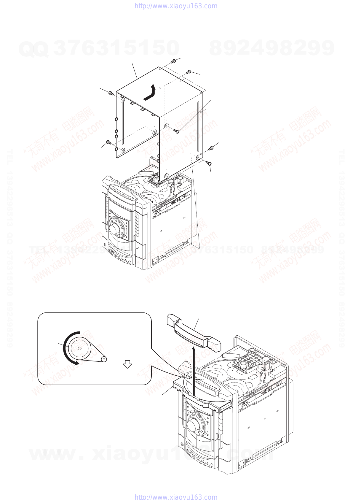
3-2. Case ................................................................................. 8
3-3. Loading Panel.................................................................. 8
3-4. Tuner Pack ....................................................................... 9
3-5. DVD Mechanism Deck ................................................... 9
3-6. Front Panel Assy.............................................................. 10
3-7. Tape Mechanism Deck, MIC Board................................ 10
3-8. CD-SW Board, Panel Board............................................ 11
3-9. FUNCTION Board, JOG Board ...................................... 11
3-10. KARAOKE Board, VIDEO Board, DMB15 Board........ 12
3-11. Back Panel ....................................................................... 12
3-12. PRIMARY Board, EFFECTOR Board............................ 13
3-13. PowerAMP PC Board Assy, MAIN Board..................... 13
3-14. SURROUND Board, PA Board ....................................... 14
3-15. Power Transformer (T1200) ........................................... 14
3-16. DRIVER Board, SW Board............................................. 15
3-17. DVD Assy........................................................................ 15
3-18. Optical Pick-up................................................................ 16
3-19. SENSOR Board ............................................................... 16
3-20. MOTOR (TB) Board ....................................................... 17
3-21. MOTOR (LD) Board....................................................... 17
4. TEST MODE ............................................................... 18
5. MECHANICAL ADJUSTMENTS......................... 23
6. ELECTRICAL ADJUSTMENTS .......................... 23
TABLE OF CONTENTS
7. DIAGRAMS .......................................................... 25
7-1. Block Diagram – RF Section –....................................... 27
7-2. Block Diagram – Video Section – ................................... 28
7-3. Block Diagram – Tape/Tuner Section – .......................... 29
7-4. Block Diagram – Main Section – .................................... 30
7-5. Block Diagram – AMP Section – .................................... 31
7-6. Block Diagram – Display/Power Section –..................... 32
7-7. Printed Wiring Board – DMB15 Board (SideA) – ......... 33
7-8. Printed Wiring Board – DMB15 Board (Side B) – ........ 34
7-9. Schematic Diagram – DMB15 Board (1/4) –................ 35
7-10. Schematic Diagram – DMB15 Board (2/4) –................ 36
7-11. Schematic Diagram – DMB15 Board (3/4) –................ 37
7-12. Schematic Diagram – DMB15 Board (4/4) –................ 38
7-13. Printed Wiring Boards – CD Mechanism Boards – ....... 39
7-14. Schematic Diagram – CD Mechanism Boards – ........... 40
7-15. Printed Wiring Board – MAIN Board – .......................... 41
7-16. Schematic Diagram – MAIN Board (1/5) – ................... 42
7-17. Schematic Diagram – MAIN Board (2/5) – ................... 43
7-18. Schematic Diagram – MAIN Board (3/5) – ................... 44
7-19. Schematic Diagram – MAIN Board (4/5) – ................... 45
7-20. Schematic Diagram – MAIN Board (5/5) – ................... 46
7-21. Printed Wiring Board – PANEL Board – ........................ 47
7-22. Schematic Diagram – PANEL Board – .......................... 48
7-23. Printed Wiring Boards – CD-SW, JOG, FUNCTION
And MIC Boards – .......................................................... 49
7-24. Schematic Diagram – CD-SW, JOG, FUNCTION
And MIC Boards – .......................................................... 50
7-25. Printed Wiring Board – PA Board – ................................ 51
7-26. Schematic Diagram – PA Board – .................................. 52
7-27. Printed Wiring Board – SURROUND Board –............... 53
7-28. Schematic Diagram – SURROUND Board (1/2) –........ 54
7-29. Schematic Diagram – SURROUND Board (2/2) – ....... 55
7-30. Printed Wiring Board – EFFECTOR Board – ................. 56
7-31. Schematic Diagram – EFFECTOR Board –................... 57
7-32. Printed Wiring Board – VIDEO Board – ........................ 58
7-33. Schematic Diagram – VIDEO Board – .......................... 59
7-34. Printed Wiring Boards – Power Section –....................... 60
7-35. Schematic Diagram – Power Section – .......................... 61
7-36. Printed Wiring Board – KARAOKE Board – ................. 62
7-37. Schematic Diagram – KARAOKE Board – ................... 62
7-38. IC Pin Function Description............................................ 65
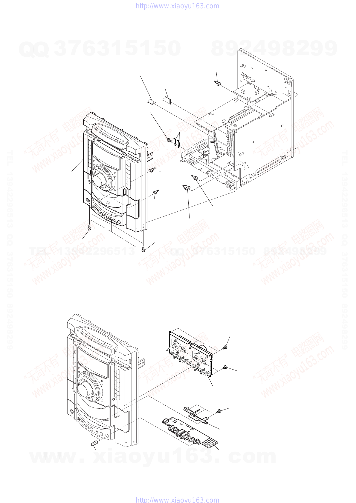
8. EXPLODEDVIEWS
8-1. Case, Back Panel Section ................................................ 75
8-2. Front Panel Section-1 ...................................................... 76
8-3. Front Panel Section-2 ...................................................... 77
8-4. Chassis Section................................................................ 78
8-5. DVD Mechanism Section-1 (CDM74HF-DVBU101).... 79
8-6. DVD Mechanism Section-2 (CDM74HF-DVBU101).... 80
9. ELECTRICAL PARTS LIST .................................. 81
w
w
w
.
x
i
a
o
y
u
1
6
3
.
c
o
m
Q
Q
3
7
6
3
1
5
1
5
0
9
9
2
8
9
4
2
9
8
T
E
L
1
3
9
4
2
2
9
6
5
1
3
9
9
2
8
9
4
2
9
8
0
5
1
5
1
3
6
7
3
Q
Q
TEL 13942296513 QQ 376315150 892498299
http://www.xiaoyu163.com

4
HCD-GN1000D SECTION 1
SERVICING NOTES
NOTES ON HANDLINGTHE OPTICAL PICK-UP BLOCK
OR BASE UNIT
The laser diode in the optical pick-up block may suffer electrostatic
break-down because of the potential difference generated by the
charged electrostatic load, etc. on clothing and the human body.
During repair, pay attention to electrostatic break-down and also
use the procedure in the printed matter which is included in the
repair parts.
The flexible board is easily damaged and should be handled with
care.
NOTES ON LASER DIODE EMISSION CHECK
The laser beam on this model is concentrated so as to be focused on
the disc reflective surface by the objective lens in the optical pick-
up block. Therefore, when checking the laser diode emission,
observe from more than 30 cm away from the objective lens.
LASER DIODE AND FOCUS SEARCH OPERATION
CHECK
Carryoutthe “Scurve check” in“CD section adjustment”and check
that the S curve waveform is output several times.
UNLEADED SOLDER
Boards requiring use of unleaded solder are printed with the lead-
free mark (LF) indicating the solder contains no lead.
(Caution: Some printed circuit boards may not come printed with
the lead free mark due to their particular size)
•MODEL IDENTIFICATION
– Back Panel –
MODEL PART No.
E2 model 2-661-760-4[]
E3,E15 models 2-672-142-2[]
EA model 2-686-972-0[]
E12 model 2-686-973-0[]
MY,SP models 2-686-974-0[]
TH model 2-686-975-0[]
PH model 2-686-976-0[]
Notes on chip component replacement
•Never reuse a disconnected chip component.
•Notice that the minus side of a tantalum capacitor may be
damaged by heat.
Flexible Circuit Board Repairing
•Keep the temperature of soldering iron around 270˚C
during repairing.
•Do not touch the soldering iron on the same conductor of the
circuit board (within 3 times).
•Be careful not to apply force on the conductor when soldering
or unsoldering.
CAUTION
Use of controls or adjustments or performance of procedures
other than those specified herein may result in hazardous
radiation exposure.
SAFETY-RELATED COMPONENT WARNING!!
COMPONENTS IDENTIFIED BY MARK 0OR DOTTED LINEWITH
MARK 0ON THE SCHEMATIC DIAGRAMS AND INTHE PARTS
LIST ARE CRITICAL TO SAFE OPERATION. REPLACE THESE
COMPONENTS WITH SONY PARTS WHOSE PART NUMBERS
APPEAR AS SHOWN IN THIS MANUAL OR IN SUPPLEMENTS
PUBLISHED BY SONY.
PART No.
•Abbreviation
E2 : 120VAC Area in E model
E3 : 240VAC Area in E model
E12 : 220V-240V AC Area in E model
E15 : Iran model
EA : Saudi Arabia model
MY : Malaysia model
PH : Philippines model
SP : Singapore model
TH : Thai model
: LEAD FREE MARK
Unleaded solder has the following characteristics.
•Unleaded solder melts at a temperature about 40 °C higher
than ordinary solder.
Ordinary soldering irons can be used but the iron tip has to be
applied to the solder joint for a slightly longer time.
Soldering irons using a temperature regulator should be set to
about 350 °C.
Caution: The printed pattern (copper foil) may peel away if
the heated tip is applied for too long, so be careful!
•Strong viscosity
Unleaded solder is more viscou-s (sticky, less prone to flow)
than ordinary solder so use caution not to let solder bridges
occur such as on IC pins, etc.
•Usable with ordinary solder
It is best to use only unleaded solder but unleaded solder may
also be added to ordinary solder.
This appliance is classified as
a CLASS 1 LASER product.
This label is located on the rear
exterior.
NOTE ON REPLACEMENT OF DMB15 BOARD
New part of EEPROM (IC103) on the DMB15 board can not be
used. Therefore, if the mounted DMB15 board (A-1174-274-A or
A-1193-178-A or A-1193-183-A or A-1193-188-A) is replaced,
exchange new EEPROM with that used before the replacement.
w
w
w
.
x
i
a
o
y
u
1
6
3
.
c
o
m
Q
Q
3
7
6
3
1
5
1
5
0
9
9
2
8
9
4
2
9
8
T
E
L
1
3
9
4
2
2
9
6
5
1
3
9
9
2
8
9
4
2
9
8
0
5
1
5
1
3
6
7
3
Q
Q
TEL 13942296513 QQ 376315150 892498299
http://www.xiaoyu163.com

5
HCD-GN1000D
SECTION 2
GENERAL This section is extracted
from instruction manual.
LOCATINGTHE CONTROLS
Unit
AMP MENU e;
CD SYNC q;
Deck A ea
Deck B qk
DELAY wl
DIRECTION ql
DISC 1 ~ 3 ts
Disc tray 8
DISPLAY 2
Display 6
DVD ej
ECHO LEVEL ws
ENTER wa
EQ BAND w;
EX-CHANGE/DISC SKIP t;
FLANGER 3
GROOVE qh
ILLUMINATION 1
IR Receptor ek
MASTER VOLUME wf
MIC 1/2 (jack) wg
MIC 1/2 LEVEL wd
OPERATION DIAL ta
PHONES (jack) wj
Power illuminator 5
PRESET +/- qf
PROGRESSIVE 7
REC PAUSE/START 9
SOUND FIELD 4
SOUND FLASH wk
TAPE A/B eg
TUNER/BAND eh
TUNING +/- qg
?/1 (on/standby) el
ZOPEN/CLOSE rl
nN (play) qa
.> (gobackward/forward)
qf
mM (rewind/fast
forward) qg
X(pause) qs
x(stop) qd
A Z(Eject A) es
B Z(Eject B) qj
ALPHABETICAL ORDER
A - D
E - L
M - R
S - Z
SYMBOLS
TV/SAT ef
VIDEO INPUT (jacks) wh
VIDEO ed
Top Panel
Front Panel
1234 5678
9
q;
qa
qs
qd
qf
qg
qh
qj
qk
w
a
w;
ql
w
s
w
d
w
f
w
g
w
h
w
j
e;
wl
wk
ea
es
ed
ef
eg
eh
ej
ek
el
tsta t;rl
w
w
w
.
x
i
a
o
y
u
1
6
3
.
c
o
m
Q
Q
3
7
6
3
1
5
1
5
0
9
9
2
8
9
4
2
9
8
T
E
L
1
3
9
4
2
2
9
6
5
1
3
9
9
2
8
9
4
2
9
8
0
5
1
5
1
3
6
7
3
Q
Q
TEL 13942296513 QQ 376315150 892498299
http://www.xiaoyu163.com

6
HCD-GN1000D
1Press ?/1 to turn on the system.
2Press TIMER MENU.
The hour indication flashes in the display.
3Press
V
or
v
repeatedly to set the
hour.
4Press ENTER.
The minute indication flashes in the
display.
5Press
V
or
v
repeatedly to set the
minute.
6Press ENTER.
The clock starts functioning.
To adjust the clock
1Press TIMER MENU.
“PLAY SET?” flashes in the display.
2Press
V
or
v
repeatedly to select “CLOCK
SET?”, then press ENTER.
The hour indication flashes in the display.
3Do the same procedures as step 3 to 6
above.
Notes
The clock settings are canceled when you disconnect
the power cord or if a power failure occurs.
You cannot set the clock in Power Saving Mode
Setting the clock
Remote control
ADVANCE wf
ALBUM +/- qa
ANGLE q;
AUDIO 8
CLEAR wk
DISC SKIP 3
DISPLAY ed
ENTER wh
FM MODE 7
FUNCTION +/- 4
KARAOKE MODE ea
KARAOKE PON e;
KEY CONTROL #/2 es
MENU qs
Numeric Buttons
1)
wl
PICTURE NAVI 6
PRESET + qh
PRESET - wd
REPEAT 7
REPLAY wf
SCORE 5
SLEEP eg
SLOW qj
SLOW ws
SOUND FIELD qd
STEP C wf
SUBTITLE 9
THEATRE SYNC 1
TIMER MENU eh
TIME/TEXT ef
TOP MENU wj
TUNING + qj
TUNING - ws
TV w;
TV CH + qh
TV CH - wd
TV/VIDEO eg
TV VOL +/-
1)
qf
TV &/1
(on/standby) 2
VOLUME +/-
1)
qf
?/1 (on/standby) 2
x(stop) qk
X(pause) ql
H
1)
(play) wa
>(go forward) qh
.(go backward) wd
M(fast forward) qj
m(rewind) ws
V/v/B/bwh
10/0 wl
-/-- wk
ORETURN wg
DISPLAY qg
c STEP wf
1)
Thenumericbutton5,TVVOL
+, VOLUME + and H
buttons have a tactile dot. Use
the tactile dot as a reference
when operating the system.
ALPHABETICAL ORDER
A - L
M - S
T - Z
NUMBERS AND SYMBOLS
7
5
q;
qh
qj
qk
ql
wa
wd
wf
wh
wj
wk
wl
ea
es
edef
eg
eh
e;
qg
qf
qs
qa
9
8
6
4
3
1
2
w;
ws
wg
qd
w
w
w
.
x
i
a
o
y
u
1
6
3
.
c
o
m
Q
Q
3
7
6
3
1
5
1
5
0
9
9
2
8
9
4
2
9
8
T
E
L
1
3
9
4
2
2
9
6
5
1
3
9
9
2
8
9
4
2
9
8
0
5
1
5
1
3
6
7
3
Q
Q
TEL 13942296513 QQ 376315150 892498299
http://www.xiaoyu163.com

7
HCD-GN1000D
SECTION 3
DISASSEMBLY
Note:
• This set can be disassembled in the order shown below.
3-1. DISASSEMBLY FLOW
3-2. CASE
(Page 8)
3-3. LOADING PANEL
(Page 8)
3-4.TUNER PACK
(Page 9)
3-15. POWER TRANSFORMER
(T1200)
(Page 14)
3-13. POWER AMP PC BOARD ASSY,
MAIN BOARD
(Page 13)
3-5. DVD MECHANISM DECK
(Page 9)
3-16. DRIVER BOARD,
SW BOARD
(Page 15)
3-12. PRIMARY BOARD
EFFECTOR BOARD
(Page 13)
3-20. MOTOR (TB) BOARD
(Page 17)
3-21. MOTOR (LD) BOARD
(Page 17)
3-19. SENSOR BOARD
(Page 16)
3-14. SURROUND BOARD,
PA BOARD
(Page 14)
3-9. FUNCTION BOARD,
JOG BOARD
(Page 11)
3-6. FRONT PANEL ASSY
(Page 10)
3-8. CD-SW BOARD,
PANEL BOARD
(Page 11)
3-7.TAPE MECHANISM DECK,
MIC BOARD
(Page 10)
3-11. BACK PANEL
(Page 12)
3-10. KARAOKE BOARD,
VIDEO BOARD,
DMB15 BOARD,
(Page 12)
3-17. DVD ASSY
(Page 15)
3-18. OPTICAL PICK-UP
(Page 16)
SET
w
w
w
.
x
i
a
o
y
u
1
6
3
.
c
o
m
Q
Q
3
7
6
3
1
5
1
5
0
9
9
2
8
9
4
2
9
8
T
E
L
1
3
9
4
2
2
9
6
5
1
3
9
9
2
8
9
4
2
9
8
0
5
1
5
1
3
6
7
3
Q
Q
TEL 13942296513 QQ 376315150 892498299
http://www.xiaoyu163.com

8
HCD-GN1000D
3-2. CASE
3-3. LOADING PANEL
1
two screws
(case 3 TP2)
(3
×
8)
2
screw (case 3 TP2
)
(3
×
12)
5
two screws
(+BVTP 3
×
12)
8
3
two screws
(case 3 TP2)
(3
×
8)
4
screw
(case 3 TP2)
(3
×
12)
7
three screws
(+BVTP 3
×
8)
6
two screws
(+BVTP 3
×
12)
9
CASE
DVD mechanism deck (CDM74HF-DVBU101)
1
Turn the pulley to the arrow direction.
Front side
Pulley
2
Pull out disc tray.
3
4
loading panel
w
w
w
.
x
i
a
o
y
u
1
6
3
.
c
o
m
Q
Q
3
7
6
3
1
5
1
5
0
9
9
2
8
9
4
2
9
8
T
E
L
1
3
9
4
2
2
9
6
5
1
3
9
9
2
8
9
4
2
9
8
0
5
1
5
1
3
6
7
3
Q
Q
TEL 13942296513 QQ 376315150 892498299
http://www.xiaoyu163.com

9
HCD-GN1000D
3-4. TUNER PACK
3-5. DVD MECHANISM DECK
1
two screws
(+BVTP 3
×
8)
2
wire (flat type)
(CN1)
3
tuner pack
6
DVD mechanism deck
7
wire (flat type)
(CN701)
8
wire (flat type)
(CN521)
3
three screws
(+BVTP 3
×
10)
1
three screws
(+BVTP 3
×
10)
2
screw
(+BVTP 3
×
10)
0
wire (flat type)
(CN520)
qa
connector
(CN401)
9
connector
(CN505)
qs
connector
(CN800)
4
screw
(+BVTP 3
×
10)
5
screw
(+BVTP 3
×
10)
w
w
w
.
x
i
a
o
y
u
1
6
3
.
c
o
m
Q
Q
3
7
6
3
1
5
1
5
0
9
9
2
8
9
4
2
9
8
T
E
L
1
3
9
4
2
2
9
6
5
1
3
9
9
2
8
9
4
2
9
8
0
5
1
5
1
3
6
7
3
Q
Q
TEL 13942296513 QQ 376315150 892498299
http://www.xiaoyu163.com

10
HCD-GN1000D
3-6. FRONT PANEL ASSY
3-7. TAPE MECHANISM DECK, MIC BOARD
3
three screws
(+BVTP 3
×
10)
2
three screws
(+BVTP 3
×
10)
1
screw
(+BV3 (3-CR))
lug
4
front panel assy
5
connector
(CN100)
6
wire (flat type)
(CN508)
7
wire (flat type)
(CN509)
8
connector
(CN504)
9
connector
(CN1102)
0
connector
(CN503)
qa
connector
(CN1100)
1
three screws
(+BVTP2.6 (3CR))
2
two screws
(+BVTP2.6 (3CR)
)
3
tape mechanism deck
4
three screws
(+BVTP2.6 (3CR))
5
bracket (MIC)
7
MIC board
6
knob (MIC)
w
w
w
.
x
i
a
o
y
u
1
6
3
.
c
o
m
Q
Q
3
7
6
3
1
5
1
5
0
9
9
2
8
9
4
2
9
8
T
E
L
1
3
9
4
2
2
9
6
5
1
3
9
9
2
8
9
4
2
9
8
0
5
1
5
1
3
6
7
3
Q
Q
TEL 13942296513 QQ 376315150 892498299
http://www.xiaoyu163.com

11
HCD-GN1000D
3-9. FUNCTION BOARD, JOG BOARD
3-8. CD-SW BOARD, PANEL BOARD
5
three screws
(+BVTP2.6 (3CR))
1
two screws
(+BVTP2.6 (3CR))
6
wire (flat type)
(CN900)
7
wire (flat type)
(CN902)
4
three screws
(+BVTP2.6 (3CR))
3
CD-SW board
8
PANEL boar
d
CD-SW board
CD-SW board
bracket portion
button (DISC)
button (DISC)
button (DISC)
(side view)
bracket portion
AA
B
B
2
Pull up the bracket portion of button (DISC) in the arrow
A
direction and
pull out CD-SW board in the arrow
B
direction.
3
FUNCTION board
2
seven screws
(+BVTP2.6 (3CR))
5
two screws
(+BVTP2.6 (3CR))
6
two screws
(+BVTP2.6 (3CR))
1
knob vol
4
knob jog assy
7
JOG board
w
w
w
.
x
i
a
o
y
u
1
6
3
.
c
o
m
Q
Q
3
7
6
3
1
5
1
5
0
9
9
2
8
9
4
2
9
8
T
E
L
1
3
9
4
2
2
9
6
5
1
3
9
9
2
8
9
4
2
9
8
0
5
1
5
1
3
6
7
3
Q
Q
TEL 13942296513 QQ 376315150 892498299
http://www.xiaoyu163.com

12
HCD-GN1000D
3-11. BACK PANEL
3-10. KARAOKE BOARD, VIDEO BOARD,
DMB15 BOARD
3
wire (flat type)
(CN801)
4
two screws
(+BVTP 3
×
10)
1
two screws
(+BVTP 3
×
10)
5
VIDEO board
2
KARAOKE board
7
two screws
(+BVTP 3
×
10)
6
screw
(+BVTP 3
×
10)
8
CDM cover
qa
two screws
(+BVTP 3
×
10)
9
connector
(CN201)
0
wire (flat type)
(CN101)
qs
two screws
(+BVTP 3
×
10)
qd
DMB15 board
qf
bracket (mediatec)
1
connector
(CN1200)
2
connector
(CN1204)
3
connector
(CN1202)
4
wire (flat type)
(CN1501)
7
screw (+BVTP 3
×
10
)
5
seven screws
(+BVTP 3
×
10)
6
two screws
(+BVTP 3
×
10)
8
two screws
(+BVTP 3
×
10)
0
connector
(CN580)
9
back panel
w
w
w
.
x
i
a
o
y
u
1
6
3
.
c
o
m
Q
Q
3
7
6
3
1
5
1
5
0
9
9
2
8
9
4
2
9
8
T
E
L
1
3
9
4
2
2
9
6
5
1
3
9
9
2
8
9
4
2
9
8
0
5
1
5
1
3
6
7
3
Q
Q
TEL 13942296513 QQ 376315150 892498299
http://www.xiaoyu163.com

13
HCD-GN1000D
3-13. POWER AMP PC BOARD ASSY, MAIN BOARD
3-12. PRIMARY BOARD ,EFFECTOR BOARD
1
connector
(CN101)
2
connector
(CN201)
3
screw
(+BVTP 3
×
8)
5
two screws
(+BVTP 3
×
10)
4
PRIMARY board
6
EFFECTOR board
4
connector
(CN1213)
5
connector
(CN1212)
6
connector
(CN1215)
1
connector
(CN582)
qs
connector
(CN105)
7
screw
(+BV3 (3-CR))
2
two screws
(+BV3 (3-CR))
8
two screws
(+BV3 (3-CR))
9
screw
(+BV3 (3-CR))
0
screw
(+BVTP 3
×
10)
qa
power AMP PC board assy
qf
two screws
(+BVTP 3
×
8)
qg
screw
(+BVTP 3
×
8
)
qd
screw
(+BVTP 3
×
8)
lug
qh
MAIN board
3
DC fan
w
w
w
.
x
i
a
o
y
u
1
6
3
.
c
o
m
Q
Q
3
7
6
3
1
5
1
5
0
9
9
2
8
9
4
2
9
8
T
E
L
1
3
9
4
2
2
9
6
5
1
3
9
9
2
8
9
4
2
9
8
0
5
1
5
1
3
6
7
3
Q
Q
TEL 13942296513 QQ 376315150 892498299
http://www.xiaoyu163.com

14
HCD-GN1000D
3-15. POWERTRANSFORMER (T1200)
3-14. SURROUND BOARD, PA BOARD
6
connector
(CN607)
5
connector
(CN602)
2
two screws
(+BVTP 3
×
10)
1
four screws
(transistor)
4
SURROUND board
7
two screws
(+BVTP 3
×
10)
8
holder
9
two screws
(+BVTP 3
×
10)
0
two screws
(transistor)
qa
two screws
(+BVTP 3
×
10)
qd
screw
(+BVTP 3
×
10)
3
screw (+BV3 (3-CR))
qs
heat sink
qf
bracket
qg
PA board
4
connector
(CN1213)
5
connector
(CN1212)
7
three screws
3
DC fan
(M892)
2
two screws
(+BV3 (3-CR))
8
three screws
9
power transfomer (T1200)
TRANS board
1
connector
(CN582)
6
connector
(CN1215)
w
w
w
.
x
i
a
o
y
u
1
6
3
.
c
o
m
Q
Q
3
7
6
3
1
5
1
5
0
9
9
2
8
9
4
2
9
8
T
E
L
1
3
9
4
2
2
9
6
5
1
3
9
9
2
8
9
4
2
9
8
0
5
1
5
1
3
6
7
3
Q
Q
TEL 13942296513 QQ 376315150 892498299
http://www.xiaoyu163.com

15
HCD-GN1000D
3-16. DRIVER BOARD, SW BOARD
3-17. DVD ASSY
3
connector (CN703)
4
DRIVER
board
6
SW board
2
wire (flat type)
(CN702)
1
two
screws
(+BTTP (M2.6))
5
screw
(+BTTP (M2.6))
1
floating
screw
(+PTPWH M2.6)
2
DVD
assy
w
w
w
.
x
i
a
o
y
u
1
6
3
.
c
o
m
Q
Q
3
7
6
3
1
5
1
5
0
9
9
2
8
9
4
2
9
8
T
E
L
1
3
9
4
2
2
9
6
5
1
3
9
9
2
8
9
4
2
9
8
0
5
1
5
1
3
6
7
3
Q
Q
TEL 13942296513 QQ 376315150 892498299
http://www.xiaoyu163.com

16
HCD-GN1000D
3-18. OPTICAL PICK-UP
3-19. SENSOR BOARD
1
insulator scre
w
6
insulator
2
insulator screw
3
insulator screw
4
insulator screw
7
insulator
5
optical pick-up
(KHM-310CAB/C2NP)
8
insulator
9
insulator
2
t
ray
3
b
elt (table)
5
p
ulley (table)
8
s
crew
(+BTTP (M2.6))
0
SENSOR board
7
g
ear (geneva)
9
connector
(
CN731)
1
floating
screw
(+PTPWH M2.6)
6
floating
screw
(+PTPWH M2.6)
4
floating
screw
(+PTPWH M2.6)
w
w
w
.
x
i
a
o
y
u
1
6
3
.
c
o
m
Q
Q
3
7
6
3
1
5
1
5
0
9
9
2
8
9
4
2
9
8
T
E
L
1
3
9
4
2
2
9
6
5
1
3
9
9
2
8
9
4
2
9
8
0
5
1
5
1
3
6
7
3
Q
Q
TEL 13942296513 QQ 376315150 892498299
http://www.xiaoyu163.com

17
HCD-GN1000D
3-21. MOTOR (LD) BOARD
3-20. MOTOR (TB) BOARD
6
Remove the two solderings of motor.
8
MOTOR (TB) board
7
t
able motor assy (M741)
5
two
screws
(+BTTP (M2.6))
4
3
wire (flat type) (CN742)
1
stopper
2
stopper
table
2
Remove the two solderings of motor.
4
MOTOR (LD) board
1
b
elt (loading)
5
l
oading motor assy (M751)
3
two
screws
(+BTTP (M2.6))
w
w
w
.
x
i
a
o
y
u
1
6
3
.
c
o
m
Q
Q
3
7
6
3
1
5
1
5
0
9
9
2
8
9
4
2
9
8
T
E
L
1
3
9
4
2
2
9
6
5
1
3
9
9
2
8
9
4
2
9
8
0
5
1
5
1
3
6
7
3
Q
Q
TEL 13942296513 QQ 376315150 892498299
http://www.xiaoyu163.com

18
HCD-GN1000D SECTION 4
TEST MODE
2. The DVD ring indicators, the line below DVD ring indicators
and TAPE A and B indicators flash synchronously on the
fluorescent indicator tube. The function is changed to TV.
*Check of Amplifier
1. Press [EQ BAND] button repeatedlyuntil amessage “GEQMAX”
appears on the fluorescent indicator tube. GEQ increases to its
maximum.
2. Press [EQ BAND] buttonrepeatedly until amessage “GEQ MIN”
appears on the fluorescent indicator tube. GEQ decreases to its
minimum.
3. Press [EQ BAND] button repeatedly until a message “GEQ
FLAT” appears on the fluorescent indicator tube. GEQ set to
flat.
4. When the [MASTER VOLUME] knob is turned clockwise even
slightly, the sound volume increases to its maximum and a
message“VOLUME MAX” appearson thefluorescent indicator
tube.
5. When the [MASTER VOLUME] knob isturned counter-clockwise
even slightly, the sound volume decreases to its minimum and
a message “VOLUME MIN” appears on the fluorescent
indicator tube.
*Tape function
1. When a tape is inserted in Deck B and recording is started, the
function is changed to TV automatically. When [CD SYNC]
button is pressed during recording in function,ALC (Automatic
Logic Control) is turned on.
2. During recording, press mbutton will stop the recording
and the function is changed to TAPE B and rewind the tape in
Deck B until the recording start position and playback of the
tape in Deck B is started. If [REC PAUSE/ START] button is
pressedfor a pauseand pressedagain to resumerecording during
recording time, when the tape is rewind, the tape will be rewind
until the position where the pause is applied.
*To release from Common Test mode
1. To release from this mode, press
?/1
button.
2. The cold reset is enforced at the same time.
[COLD RESET]
•The cold reset clears all data including preset data stored in the
RAM to initial conditions.
Procedure:
1. Press
?/1
button to turn on the system.
2. Press
x
button, [ENTER] button and
?/1
button
simultaneously.
3. The message “COLD RESET” appears on the fluorescent
indicator tube. Then, the fluorescent indicator tube becomes
blank for while, and the set is reset.
[VACS ON/OFF]
•This mode is used to switch ON and OFF the VACS (Variable
Attenuation Control System).
Procedure:
1. Press
?/1
button to turn on the system.
2. Press
x
button and [ILLUMINATION] buttonsimultaneously.
The message “VACS OFF” or “VACS ON” appears on the
fluorescent indicator tube.
[TUNER STEP CHANGE]
•The step interval ofAM channels can be toggled between 9 kHz
and 10 kHz.
This mode is not available for Saudi Arabia model.
[PANELTEST MODE]
•This mode is used to check the fluorescent indicator tube, LEDs,
buttons, MASTER VOLUME knob, OPERATION DIAL knob,
model, destination, software version and VACS level.
Procedure:
1. Press
x
button, [ENTER] button and [DISC 2] button
simultaneously.
2. All LEDs and segments in fluorescent indicator tube are lighted up.
3. When you want to enter to the software version display mode,
press [DISC 1] button. The model information appears on the
fluorescent indicator tube. Press [DISC 1] button again to view
the destination information.
4. Each time [DISC 1] button is pressed, the display changes from
MC version, GC version, SYS version, DVD version, ST
version, TC version, TA version, TM version in this order, and
returns to the model information display.
5. When [DISC 3] button is pressed while the version numbers
are being displayed except model and destination, the date of
the software creation appears. When [DISC 3] button is pressed
again, the display returns to the software version display. When
[DISC 1] button ispressed whilethe dateof thesoftware creation
is being displayed, the date of the software creation is displayed
in the same order of software version display.
6. Press [DISC 2] button, the key check mode is activated.
7. In the key check mode, the fluorescent indicator tube displays
“K0 V0 J0”.
Each time a button is pressed, “K” value increases. However,
oncea button hasbeen pressed,it is nolonger takeninto account.
“J” value increaes in the manner of 0,1,2,3... if [OPERATION
DIAL] knob is turned clockwise, or it decreases in the manner
of 0,9,8,7... if [OPERATION DIAL] knob is turned counter-
clockwise.
“V” value increases in the manner of 0, 1, 2, 3 ... if [MASTER
VOLUME] knob is turned clockwise, or it decreases in the
manner of 0, 9, 8,7 ... if [MASTER VOLUME] knob is turned
counter-clockwise.
8. When [DISC 3] button is pressed after all LEDs and segments
in fluorescent indicator tube light up, the fluorescent indicator
tube displays “VACS A+B F APC”. A is conventional VACS
level which is triggered by signal level. B is Thermal VACS
level which is triggered by the temperature F is shown if the fan
is turned in high speed and vice-versa. C is VACS level which
is trigger by APVACS (Abuse Protection VACS).
The signal level, which will trigger VACS A is shown in the
center area of the fluorescent indicator tube.
9. When [EX-CHANGE/DISC SKIP] button is pressed after all
LEDs and segments in fluorescent indicator tube light up,
alternate segments in fluorescent indicator tube and LED would
light up. If you press [EX-CHANGE/DISC SKIP] button again,
another half of alternate segments in fluorescent indicator tube
andLEDswould lightup. Pressing [EX-CHANGE/DISC SKIP]
button again would cause all LED and segments lights up.
10. To release from this mode, press three buttons in the same
manner as step 1, or disconnect the power cord.
[COMMONTEST MODE]
•This mode is used to check operations of the respective sections
of Amplifier and Tape.
Procedure:
•To enter Common Test Mode
1. Press
x
button, [ENTER] button and [DISC 3] button
simultaneously.
w
w
w
.
x
i
a
o
y
u
1
6
3
.
c
o
m
Q
Q
3
7
6
3
1
5
1
5
0
9
9
2
8
9
4
2
9
8
T
E
L
1
3
9
4
2
2
9
6
5
1
3
9
9
2
8
9
4
2
9
8
0
5
1
5
1
3
6
7
3
Q
Q
TEL 13942296513 QQ 376315150 892498299
http://www.xiaoyu163.com

19
HCD-GN1000D
Procedure:
1. Press
?/1
button to turn on the system.
2. Press [TUNER/BAND] button repeatedly to select the “AM”.
3. Press
?/1
button to turn off the system.
4. Press [ENTER] button and
?/1
button simultaneously. The
system will turn on automatically. The message “AM 9k STEP”
or “AM 10k STEP” appears on the fluorescent indicator tube
and thus the channel step is changed.
[DVD SHIP MODE (WITH MEMORY CLEAR)]
•This mode moves the optical pick-up to the position durable to
vibration and clears all data including preset data stored in the
RAM to initial conditions. Use this mode when returning the
set to the customer after repair.
Procedure:
1. Press
?/1
button to turn on the system.
2. Select DVD function.
3. Press
x
button, [SOUND FLASH] button and
?/1
button
simultaneously during “DVD NO DISC” condition. The
system will turn off automatically.
4. After the “STANDBY” blinking display finishes, a message
“MECHA LOCK” appears on the fluorescent indicator tube and
the DVD ship mode is set.
[DVD SHIP MODE (WITHOUT MEMORY CLEAR)]
•This mode moves the optical pick-up to the position durable to
vibration. Use this mode when returning the set to the customer
after repair.
Procedure:
1. Press
?/1
button to turn on the system.
2. Select DVD function.
3. Press [DVD] button and
?/1
button simultaneously during
“DVD NO DISC” condition. The system will turn off
automatically.
4. After the “STANDBY” blinking display finishes, a message
“MECHA LOCK” appears on the fluorescent indicator tube and
the DVD ship mode is set.
[DVD TRAY LOCK MODE]
•This mode is used to lock the disc tray. When this mode is
activated, the disc tray will not open when [OPEN/CLOSE]
button or [EX-CHANGE/DISC SKIP] button is pressed. The
message “LOCKED” appears on the fluorescent indicator tube.
Procedure:
1. Press
?/1
button to turn on the system.
2. Select DVD function.
3. Press
x
button and [OPEN/CLOSE] button simultaneously
and hold down until “LOCKED” or “UNLOCKED” appears
on the fluorescent indicator tube (around 5 seconds).
[TV/SAT SWITCHING]
•This mode let you switch from TV to SAT and vice-versa.
Procedure:
1. Press
?/1
button to turn on the system.
2. Select TV function.
3. Press [TV/SAT] button and
?/1
button simultaneously. The
function will change to SAT. Press the same buttons again to
change from SAT to TV.
[DVD COLOR SYSTEM]
•This mode let you change the color system of the video output
from PAL to NTSC or vice-versa.
Procedure:
1. Press
?/1
button to turn on the system.
2. Select DVD function.
3. Press
?/1
button again to turn off the system.
4. Press Xbutton and
?/1
button simultaneously. The system
will turn on automatically.
5. The message “COLOR PAL” or “COLOR NTSC” appears on
the fluorescent indicator tube.
[REMOTE COMMANDER DISABLE MODE]
•Thismode let youdisable theremote commander reception.When
this mode is activated, the system will not response if the button
on the remote commander is pressed. The message
“RemoteDisable” appears on the fluorescent indicator tube.This
mode is essential for conducting test and repairing when no
interruption from the other remote commander is expected. This
mode is cancelled automatically when the AC power supply is
cutoff.
Procedure:
1. Press
?/1
button to turn on the system.
2. Press
x
button, [FLANGER] button and [DISC 2] button
simultaneousl untill“RemoteDisable” or “RemoteEnable”
appears on the fluorescent indicator tube.
[TCM OFFLINE MODE]
• This mode is used to prevent the system from turning off
automatically when TCM is not connected. Therefore,
measurements can be done even when TCM is not connected
during production.
• Procedure:
1. When the system is turned off, press [EQ BAND] button, [TAPE
A/B] button and
?/1
button simultaneously. The system will
turn on automatically.
2. The message “TCM OFFLINE” will appears on the fluorescent
indicator tube.
• To release from TCM Offline Mode, perform “COLD RESET” or
turn off the power supply.
[MTK FIRMWARE DISPLAY]
• This mode is used to display the MTK firmware version.
• Procedure:
1. Press
?/1
button to turn on the system.
2. Press [DVD] button to switch to DVD function.
3. Press
?/1
button again to turn off the system.
4. Press
x
button and
?/1
button.
The system turns on automatically.
5. The version of MTK firmware appears on the TV screen.
[MTK OFFLINE]
• This mode is used to enable audio output from the function other
than DVD function in order to check the audio output from the
system without connecting MTK.
• Procedure:
1. Press
?/1
button to turn on the system.
2. Press
x
button, [FLANGER] button and [DISC 1] button
simultaneously and the message “MTK OFFLINE” appears on
the fluorescent indicator tube.
w
w
w
.
x
i
a
o
y
u
1
6
3
.
c
o
m
Q
Q
3
7
6
3
1
5
1
5
0
9
9
2
8
9
4
2
9
8
T
E
L
1
3
9
4
2
2
9
6
5
1
3
9
9
2
8
9
4
2
9
8
0
5
1
5
1
3
6
7
3
Q
Q
TEL 13942296513 QQ 376315150 892498299
http://www.xiaoyu163.com

20
HCD-GN1000D
[DVD SERVICE MODE]
•This mode let you make diagnosis and adjustment easily by us-
ing the remote commander and TV. The instructions, diagnostic
results, etc. are given on the on-screen display (OSD).
Procedure:
1. Press
?/1
button to turn on the system.
2. Select DVD function.
3. Press
x
button and [OPEN/CLOSE] button simultaneously
and then turn [MASTER VOLUME] knob clockwise.
4. The message “SERVICE IN” appears on the fluorescent
indicator tube and the Top Menu of Remocon Diagnosis Menu
appears on the on-screen display on the TV. The model name
and revision number is displayed at the bottom of the on-screen
display.
Remocon Diagnosis Menu
0. External Chip Check
1. Servo Parameter Check
2. Drive Manual Operation
3. Emergency History Check
4. Version information
Model name : XXXXX-XX
IF-con : Ver.XX.XX(XXXX)
Syscon : Ver.X.XXX
5. To execute each function, press its number by using numeric
button on the remote commander.
6. To release from this mode, press
?/1
button to turn off the
system.
[EXECUTE IOP MEASUREMENT]
In order to execute mirror time adjustment, the following standard
procedures must be followed.
1. Enter DVD Service Mode.
Remocon Diagnosis Menu
0. External Chip Check
1. Servo Parameter Check
2. Drive Manual Operation
3. Emergency History Check
4. Version information
Model name : XXXXX-XX
IF-con : Ver.XX.XX(XXXX)
Syscon : Ver.X.XXX
2. Select “2. Drive Manual Operation” by pressing [2] button on
the remote commander. The screen will appear as follows.
Drive Manual Operation
1. Servo Control
2. Track/Layer Jump
3. Manual Adjustment
4. Tray Aging Mode
5. MIRR time adjust
0. Return to top Menu
3. Select “3. Manual Adjustment” by pressing [3] button on the
remote commander. The screen will appear as follows.
Manual Adjust
1. Track Balance Adjust:
2. Track Gain Adjust:
3. Focus Balance Adjust:
4. Focus Gain Adjust:
5. Eq boost Adjust:
6. Iop:
7. TRV. Level:
8. S curve(FE) Level:
9. RFL(PI) Level:
0. MIRR Time:
$ 4 Change Value
[RETURN] Return to previous menu
4. Select “6.Iop” by pressing [6] button on the remote commander
5. Wait until a hexadecimal number appear as follows.
w
w
w
.
x
i
a
o
y
u
1
6
3
.
c
o
m
Q
Q
3
7
6
3
1
5
1
5
0
9
9
2
8
9
4
2
9
8
T
E
L
1
3
9
4
2
2
9
6
5
1
3
9
9
2
8
9
4
2
9
8
0
5
1
5
1
3
6
7
3
Q
Q
TEL 13942296513 QQ 376315150 892498299
http://www.xiaoyu163.com
Table of contents
Other Sony Air Conditioner manuals
Popular Air Conditioner manuals by other brands

Frigidaire
Frigidaire FAC064J7A1 Factory parts catalog

Daikin
Daikin H-Series Technical manual

Acson international
Acson international B Series installation manual

Bosch
Bosch Climate 5000i M Series Operating instructions for users

Essick
Essick UltraCool CP 35 Specifications

Trane
Trane IntelliPak CG-SVX02B-EN Installation & operation manual