Continuous RMS
Power Output
(Lea than 0.688%
THD, both channels
driven simultaneous-
ly)
(AEP, UK,
E
model):
Power Bandwidth
(IHF):
Dynamic Headroom:
Harmonic Distortion:
Intermodulation (IM)
Distortion
(60Hr:
7kHz=4:
1):
Frequency Response:
Residual Noise:
Damping Factor:
At 20 Hz
-
20 kHz
40 + 40 watts (8 ohms)
At 1
kHz
44 + 44 watts (8 ohms)
According to DIN 45500
40 + 40 watts (8 ohms)
5 Hz
-
45 kHz
1.8 dB (‘78 IHF)
Less than 0.008% at rated output
Less than 0.008% at rated output
PHONO:
AIAA
equalization curve
f0.5dB
TUNER
DAD/AUX
TAPE 1.2
10Hz-120kHz’;OdB
Less than
35pV
(8 ohms, network A)
50 (8 ohms, 1
kHz)
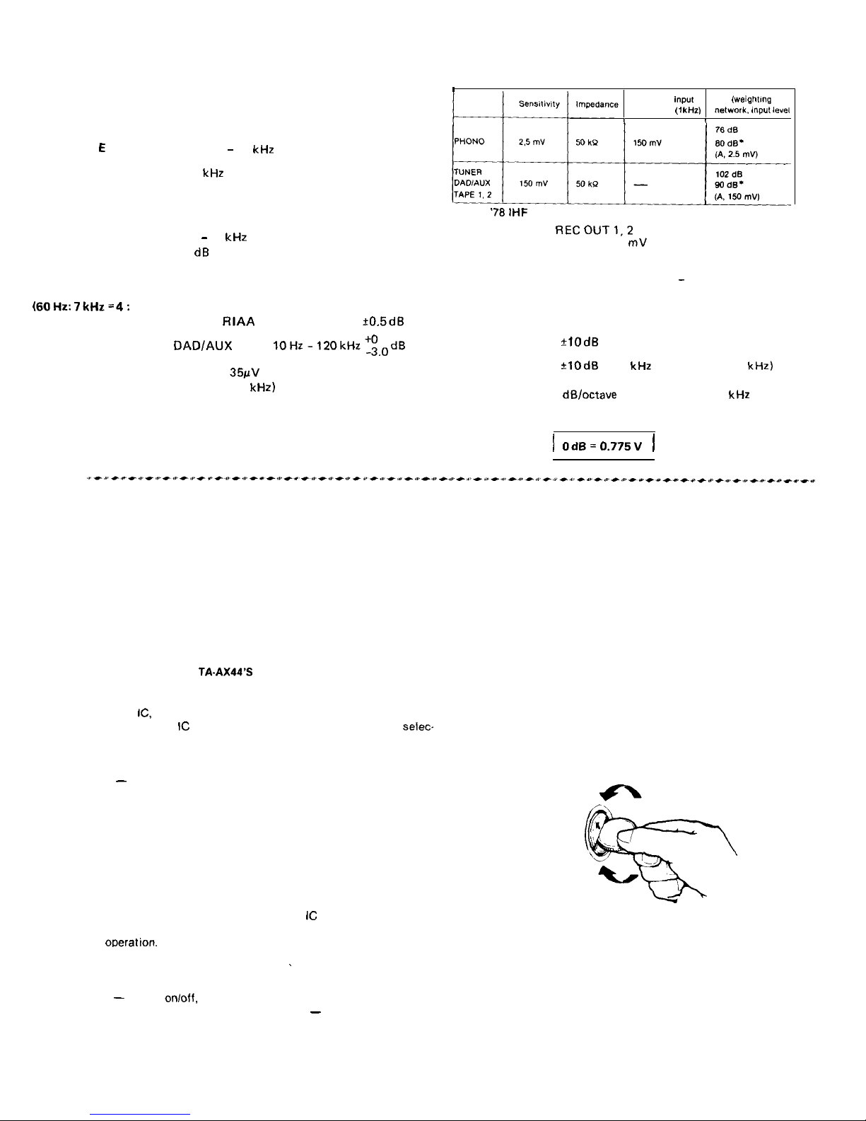
Inputs:
I
Maximum
input
SIN
(wei~hfmg
capability
(1
kliz) network,
(“put
le”e,
I
1
*
‘70
IHF
outputs:
RECOUT1,2
Voltage 150
mV
Impedance 4.7 k ohms
SPEAKER A, B
Accepts speakers of 8
-
16 ohms.
HEADPHONES
Accepts low and high impedance head-
phones.
Tone Controls: BASS
+lOdB
at 100 Hz (turnover freq. 500 Hz)
TREBLE
?lOdB
at 10 kHz (turnover freq. 2 kHz)
Subsonic Filter: 6 dB/octave attenuation below 15 Hz
High Filter: 6 dB/octave attenuation above 9 kHz
Muting: -20dB
1
OdB=0.775V
1
FEATURES
The TA-AX44 integrated stereo amplifier incorporates a number of
technical breakthroughs in circuit design. On its attractive front
panel most of the controls and switches are “touch pad” switches
and the tone, filter and volume settings are shown by fluorescent
displays.
HIGHLIGHTS OF THE TA-AX44’S CIRCUIT
ASP (Audio Signal Processor) IC in the preamplifier stage
Sony has developed a new audio device, called the Audio Signal
Processor
IC,
which can digitally control the tone, filter and volume
settings. The ASP
IC
also permits electronic program source
selec
tion. Mechanical controls and switches have been practically
eliminated from the front panel. In combination with a microcom-
puter and a non-volatile memory IC, the ASP IC offers greater flex-
ibility
-
an Acoustic Function, an ability to store and recall two
sets of tonal adjustments.
Legato linear power amplifier stage
The operation of the power amplifier stage is stable without any
observable distortion up through the higher frequencies. We call
this power amp “Legato Linear” because its switching distortion is
very low and its output waveform smooth.
Simple, straight signal path layout
A heat-pipe cooling system and the ASP
IC
layout near the input
and output terminals minimize wiring losses and allow low distor-
tion
ooeration.
OPERATING VOLTAGE
Before connecting the unit to the power source, check that the
operating voltage of your unit is the same as the local power line
voltage.
The Continental European model (AEP model) operates on 220 V
ac (or 240 V ac adjustable by authorized Sony personnel).
The United Kingdom model (UK model) operates on 240 V ac (or
220 V ac adjustable by authorized Sony personnel).
The model for other countries (E model) operates on either 120,
220 or 240 V ac. The voltage selector is located on the rear
panel. If the selector must be reset, disconnect the ac power
cord and turn the selector with a coin so that the arrow mark
of the selector points to the proper voltage figure.
The US, Canadian model operates on 120 V ac.
Wireless remote control operation
~
Using the optional RM-44 system remote controller, various opera.
tions
-
power
on/off,
program selection, acoustic setting selec-
tion, muting on/off and volume adjustment
-
can be remotely con-
trolled.