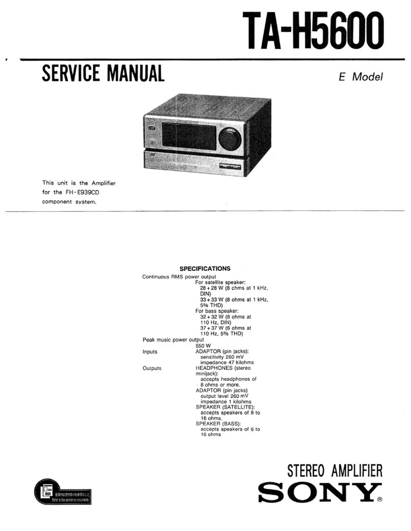
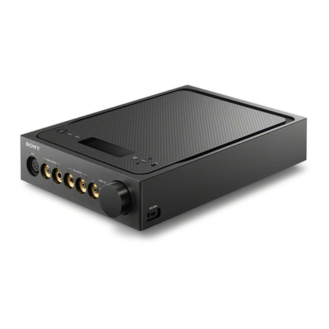
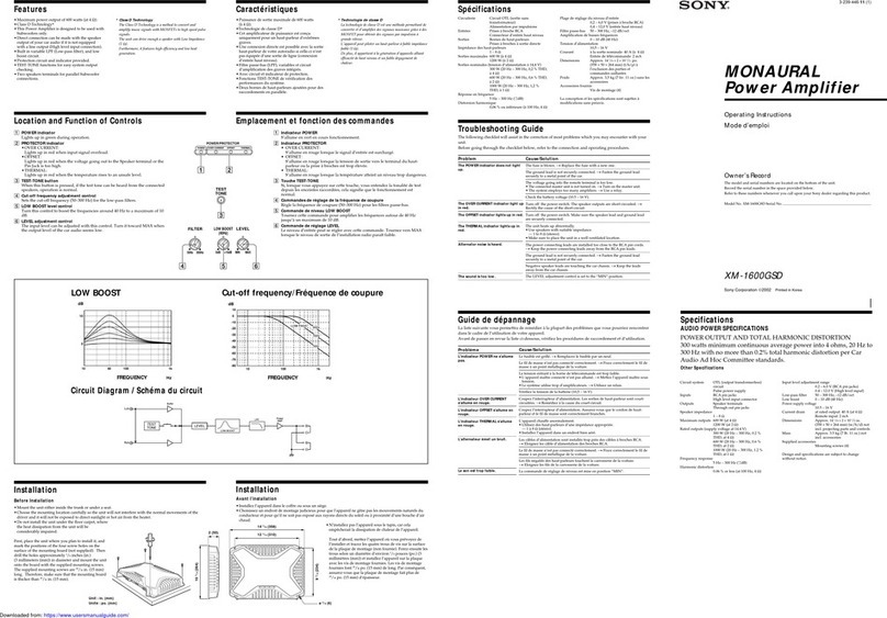
Sony TA-E80ES User manual

SERI|ICE
MANI|AL AEP Model
E Model
SPECIFICATIONS
Item Condltlon Data
Total
harmonic
distortion At rated20 Hz
20kHzoutput 0.001%
lntermodulation
(lM)
distortion
60Hz:7kHz
=4:1
atratedoutput 0.001%
Residual
noise NetvvorkA LessthatI lrv
Frequency
response PHONO
MM RIAAequâllzatlon
curve:t0.2
dB
TUNER,CD,
AUX,
TAPE1,TAPE2,
TAPE3,
ADAPTOR
IN
3Hz
-300
kHz
:!dB
Inputsensitivity PHONOMC
(3ohms) 0.17
mV,
.|00
ohms
MC(40ohms) 0.17mV.
1kohms
MM 2.5
mV,50kohms
TUNER.
CD(UNBALANCED),
AUX,
TAPE
1,TAPE2,
TAPE3.ADAPÏOR
IN 150mV,50kohms
CD(BALANCED) 300mV,20kohms
Maximum
input
capability
(1kHz) PHONO
(1
kHz,
THD0.003%l
MC 9mV
MM 150mV
S[{ (network) PHONO\4C
(0.5
mV) 83dB (A)
\'lM
(5 mV) 95
dB(A)
TUNER.
CD(UNBALANCED),
AUX.
TAPE
1.TAPE2.
TAPE3. ADAPTOR
IN 105
dB
(A)
Output
voltage
impedance TAPE1,
TAPE2,
TAPE3 150mV,
1kohms
HEADPHONES 45milliwatts
(at
I ohms)
Accepts
lowand
hlgh
imp€dance
headphones.
OUTPUT
(UNBALANCED) 1.5
V,700ohms
OUTPUT
(BALANCED) 3
V.1.2
kohms
- Continued
onPage
2 -
STEREO
CONTROL
AMPLITIER
SONY.

TA-E8OES
General
Syst€m Low-notee
FEIhtgh
gain,
NFB
type
equatizer
amplifier,
lownoise
FET,
Double-stage
ditterenilal,
push-pull
output,flat
amplifier
passive
typedirect
tonô
control
Powerrequlrements
European
countriss:Z2OV
AC,
50/60Hz
Othor
countries:
110
-120
Vor2ZO
-240
V
AC
adlustable,
50/60Hz
Powgr
consumptlon
20w
AC
outlets European
counlrles:
3swltched
200
Wmax.
Other
couhtrles:
3swltched,
S00Wmax.
Dlmendons Approx,
470
x 130
x070
mm
(w/tr/d)
Incl.
prolecilng
parts
and
controls
Welght Approx.
11,5
kg
Supplled
accessorles
Remote
commander
RM€BoB(1)
Sony
battertes
SUM-3(NS)(2)
Connectlng
cord
(1)
Deslgn
andsp€citication
subject
tochange
without
notice.
SAFETY.RELATED
COMPONENT
WARNINGI
t
coMpoNENTS
|DENT|FIED
By MARK
2\ On oorreo
L|NE
WITH
MARK
a ONTHE
SCHEMATTC
DTAGRAMS
AND IN THE PARTS LIST ARE CRITICAL TO SAFE
OPERATION. REPLACE
THESE
COMPONENTS
WITH
SONY PARTSWHOSE
PART NUMBERS
APPEAR
AS
SHOWNIN THISMANUAL OR IN SUPPLEMENTS
PUB.
LISHED
BY SONY.
Section Title
TABLE OF CONTENTS
Paqe Section Title
3. DIAGRAMS
Page
Specifications
1. GENERAL
Precautions
OperatingVoltage
Functionof Controls
System
Connections
5
J
4
6
Circuit
Boards
Location 8
SemiconductorlæadLayouts
.".. 9
PrintedWiringBoards
. ...... l0
SchematicDiagram ......... l5
EXPLODED
VTEWS ...... 19
2. DTSASSEMBLY
... ........ .7 5. ELECTRICAL
PARTS
LIST ..... 23
3-1.
3-2.
J-J.
3-4.
4.
Item Gondlllon Dala
Tone
controls BASS
(et100
Hz) i7 dB
(turnover
freq.200Hz)
i8 dB
(tu.nover
freq.400Hz)
TREBLE
(at
10
kHz) 16dB
(turnover
freq.3 kHz)
18dB
(turnover
freq.6 kHz)
SUBSONICfilter 6 dB/octave
attenuation
below15Hz
Mutlng -20dB
-2-

TA-E8OES
SECTION
1
GENERAL
)
. Unoluq
the
unit
from
the
wall
outlet
ifitisnot
tobeused
;;:;Ë;i";;ed period
oftime' Todisconnect
the
cord'
ourfit
ouioygraipingthe
plug' Never
pull
the
plug
out
bythe
cord.
. ÀioiO
installing
orleaving
the
unit
ina location:
- near
heat
sources
such
as
radiators'
airducts
or
heaters
- subiect
to
direct
sunlight
- exPosed
torain
ormoisture
- where
itisliable
tocome
into
contact
with
dust
ordirt
- that
isunventilated,
such
as
on
a bookcase'
. Should
any
liquid
orsolid
object
fall
into
the
unit'
unplug
te unit
and
have
the
unit
checked
byqualified
personnel
before
oPerating
itanY
further'
. ;ô;;;;ôrd"must bechanged
onlv
atthe
qualified
service
shoP.
. ine unit
isnot
disconnected
lrom
the
ACpowersource
aslong
asitisconnected
to
the
mains
outlet'
even
ifthe
unit
itsèlf
has
been
turned
otf'
lfvou
have
any
questionorproblem
concerning
your
unit
inâiù not
covôred
inthis
manual,
please
consult
your
nearest
SonY
dealer'
Before
connecting
the
unit
to
an
AC
outlet'
be
9u1e
that
the
ii"î"tiià ""'ùge"ot
vour
unit
is
identical
with
that
of
vour
local
Power
suPPlY'
4
Operates
on 22O
VAC,50/60
Hz'
Ooerates
oneither
1
10
- 120
V
o, ZZO
- 240
VAC,50/60
Hz'
The
voltage
selector
islocated
on
the
rear
pânel.ll the
selector
must
bereset,
disconnect
the
ACPower
cord
and
set
the
selector
tothe
propervoltage
ofYour
localPower
supPlY.
Other
countries
Æ.1

TA-E8OES
For
instruclions
refer
to
the
pages
indicated
in
the
circled
number.
E pOWenswttch
andSTANDBY
Indtcator
@
El rnpurseLEcToB and
tndtcarors@
El lolpron swnchandtndlcator
@
Eil sounce DtREcT
swtrch
andIndtcator
@
El Protecilon
andpower
on Indlcator
@
El arrenuaron
conrrot
(E
El Remore
senaor
El mulrc button
and
Indlcator
@
El suesoxlcmerswtrch
@
[Eluooesetector
@
EJaaunceconrrot
@
EJclnrnlocE LoAD
seteoor
@
@ necoursElEcron@
EJ BASS
andJREBLE
controts
and
TURNOVEB
seleclors
@
[E ourpur swftch
@
EJpxorues
pck
(srereo
phonelack)
Pour.les
détails,
sereporter
aux
pages
indiquées
dans
les
cercles.
E lnrerrupteur
d'afimentailon
(pOWER)
ettémoln
d'atrente
(STANDBY)
@
El sébcteur êttémotns
d,entrée
(lNpUT
SELEcTOR)
@
El Commrt"teurettémolnd,adaptateur
(ADAPTOR)
@
Eil Comrurateur el t6moln
desource
dlrecte
(souncE
DTRECD
@
El tgmotn
de
blocage
et
de
mlgo
sous-tenslon@
El Borron
d'anénuatlon
(ATTENUATOR)
@
EJ Dérecr"u,
de
télécommande
El touche
et
témotn
d,assourdlssement
(MUïNG)
@
E] Corrrr"reur de
f[tresubsontque
(SUBSON|C)
@
[Dlsencreurde
mode
(MoDE)
@
Ei Bouron
de
batance
(BALANCE)
@
El S_gl"cteur
de
chargement
de
celute
(cARTRtDcE
LOAD)
@
B 911ar9goesorile
d,enregtsrremenr
(REC
OUTSELECTOR)
@-
E !:_"pn: des
graves
er
des
atqus
(BASS,
TREBLE)
etséteoeurs
de
fréquence
Oe
Hyq'utsitiuniioveny
@
El Commut"teurde
sorile
(OUTPUT)
@
EI prlse
casque
(PHONES,
téléphonlque
stéréo)
12

E Powen
swltch
E f"p" deckor DATdeckcontrolsectlon
DECK
A/Bselector:
Selects
DECK
AorBtobe
controlled.
K</>>t: Locatesadesired
selection.
(AMS)
(only
for
deck
B)
</>: Play
{/}; Fastwinding
r: Stop
tl:Pause
O:Record
muting
a:Recording
E Tun"t or CD
controlsecllon
TUNER/CD
selector:
Selects
TUNERor
CDtobe
controlled.
BAND
button:Selects
theband
forapresel
station.
(only
lortuner)
SHIFT
and
PRESEIbuilons:
Selects
apreset
station.(only
for
tuner)
Presetor
program
number
(1
to9,0/10,
and
>10)
buttons:
Selects
apreset
station
(only
for
tuner)or
track
(only
forCD
PlaYer).
K</>>l: Locates
adesired
selection.(only
for
CD
player)
>: Statts
play,(only
forCD
PlaYer)
t: Stops
play.(only
forCD
PlaYer)
It:Pause
(only
for
CD
player)
El control
amplifier
secllon
Function
selectors:
Selecl
an
inputsourceof
thecontrol
amplifier.
ATTENUATOR
+/- buttons:
Controlthe
attenuatoroflhe
control
amplifier.
MUTINGbutton:
Muteslhe
sound.
E lnterrupteur
d'allmentallon
(POWEB)
E Sectlon
platlne-cassette
ou
plallne
DAT
Sélecteur
de
platine
A/B
(DECK
!y'B):Sélection
de
la
platine
AouBàcommander.
K{/>>t Localisation
d'une
plage(AMS)
(platine
B
uniquement)
</>: Lecture
<</>>: Bobinage
raPide
l: Arrêt
It:Pause
O:Silencieux
d'enregistrement
o: Enregistrement
El sectlontunerou lecteur
cD
Sélecteur
detuner/lecteur
CD
(TUNER/CD):
Sélection
du
lecteurCDou
dutuner
àcommander.
Touche
de
gamme
(BAND):
Sélection
dela
gamme
pour
une
station
présélectionnée
(tuner
uniquement).
Touches
dedécalage
etde
présélection
(SHIFT'
PRESET):
Sélection
d'une
station
présélectionnée
(tuner
uniquement).
Touches
numériques
de
présélection
oudeplage('là
9,0/'10,
et>'10):Sélection
d'unestation
présélectionnée
(tuner
uniquement)
ou
d'une
plage
(lecteur
CDuniquement),
K</>>t: Localisation
d'une
plage
donnée
(lecteur
CD
uniquement)
>: Lecture
(lecteur
CD
uniquement)
r: Arrêt
dela
lecture
(lecteur
CDuniquement)
lt:Pause
(lecteur
CD
uniquement)
Eil sectlonampllflcateur
decontrôte
Sélecteurs
de
fonction:Sélection
d'une
source
d'entrée
de
I'amplificateur
deconlrôle.
Touchesd'atténuation
(ATTENUATOR
+/-):Réglage
d'atténuation
de
I'amplificateur
decontrÔle.
Touched'assourdissement
(MUTING):
Assourdissemenl
du
son.
14

o The
power
cordshould
beconnectedlast
ofall,first
making
sure
thatthePOWER
switchisturnedoff.
. Cableconnectors
shouldbefullyinserted
into
the
jacks.
Aloose
connection
maycausehum
andnoise.
. Cord
plugs
and
jacks
arecolorcoded.
Red
plugs
and
jacks
are
for
therightchannel
(R)
andwhite
onesarefor
theleft
channel
(L).
o Le
cordond'alimentatlon
doltêtreraccordé
endernler,
en
s'assurantaupréalable
que
l'interrupteur
POWER
est
surOFF.
. Les
câbles
deconnexions
doiventêtr€
entièrement
insérés
dansles
prises,
uneconnexionrelâchée
pouvant
êtrela
causede
bruitet
de
ronflement.
r Lesfiches
et
prises
des
cordonssont
cordésavecune
couleur.
Les
fiches
et
prises
rouges
sontdeslinées
au
canaldroit
etlesblanches
aucanal
gauche.
Speaker
system
Encsintes
acoustiques
CDplayer
Lecteur
CD
I
I
I
I
I
TA-N80ES
Power
ampllfler
Amplificateur
de
pulssahce
I
I
I
ConrEctingcord(supdiêd)
I OUTPUT gordondolialsoo
(fournle)
I
ACOUTLET
Turntable
system
Platine
tourno-
disque
Graphlc
equâlizer
Êgaliseur
graphique
Tuner
Tuner
TAPE
1 CoNTROLS toawâll
outlet
vers
une
prls€
muralo
TAPE
2
Cass€tto
deck1
Platine-cassetto
1
Câssette
deck
2
Platine€assette
2
Cassgns
deck
3
Platine.casselto
3
TAPE
3
I

sEcrroN
2
DISASSEMBLY
NOTEON REPAIRING
DISASSEMBLY
ANDASSEMBLYFORSWITCHSECTION
Note: Followthe disassembly
procedure
inthe numerical
ordergiven.
DISASSEMBLY
Insertinthescrewdriverandremotethewiringasillustratedbelow,
CAUTION:Don't
pull
thewiring.
Itcauses
the
wiringdamage.
ASSEMBLY
O Turn
the
switch
knob,
sothdtthis
Posilion
is
attheend
oflefr.
O Putthe slider of switch
at the endof left.
/
N.tj

3.1. CIRCUITBOARDSLOCATION
Emodel
r--- - - -l
-/>-'-
.V6n \
'/ v///À \
/1Wè
v.
sdo"ra
', outletboard /
L-- ---t-.
power
board
microcomputer
board
power
SWboard
H.P board
tone
board
FUNCLEDboard
S.D LEDboard
VOLLEDboard
mutingSWboard
jumper board
sEcTtoN
3
DIAGRAMS
o WG:WestGermany
-8-

TA-E8OES
3.2, SEMICONDUCTOR
846208
2S41360
2sc1941-LK
2SC3423
ffi
u[,
2sc2785-HFE
"'&r
WT'
tittitil
litil[l
.'i
\
2sc3601
letter 5Ée
hl
N
,/r\
2sD774-34
ôl
hp
iï\
EC,A
WffiffiT
"'r'r.,Ï
RC78lsFA
ÉÀ
t(ù
\rur-
/1" '
1o
M5238L
ffi
]JÏÏÏlIlI'tl
r8
RC79lsFA
'fi
tv
\i[r_"
/!
al
pPA68HA-M
a----1
tl
ÏTffiTÏ
2SK147-V
2SK246.GR2
mainboard
relayboard
HZS6B1L
uz-1oBsc
1ssl20
11ES2
lf'"''*
/lJ-\
v
Y
1l
iF-
sEL221oS-C
sEL281oA-C
l,-l
AJ
'"'n
-llil-
"''
,a\
onode coth0de
sEL2sl0C
fr
il[
at\
/" ".,n*'
LEAD LAYOUTS
2sA985A
25C2275-P
N'
N]
h"ij
ruu
nl
-CE

D1
01
D1
02
Dl
03
D1
04
D't05
D1
51
D301
D401
D601
D602
D603
D604
D605
D606
D607
0608
D609
D61
0
uotl
D61
2
D61
38
D61
3A
D61
48
D614A
D61
5
D900
D901
D902
D903
D904
D905
D906
D907
D908
D909
D91
0
D91
1
D91
2
nol a
D914
D91
5
091
6
Dgl7
D91
I
D91
I
D920
D921
D922
D923
D924
D925
D926
D927
D92B
D929
D930
D931
D932
D934
D935
D936
D937
UYJÔ
D939
D940
D941
J-10
E-9
F-9
U.J
B-1
0
to
A-14
B-8
f-25
f-zJ
F-23
f -25
F-23
f -zl
E-23
F-23
G-20
G-20
E.ZJ
c-zé
E-34
E-23
E-23
t-1
5
J-JJ
J-33
K-33
K-33
K-33
t_??
N-JJ
N-J5
K-33
J-52
J-32
J-32
K-32
K-32
K-32
K-32
J-J I
K-31
K-28
J-J I
K-30
G-26
G-27
u-zô
9-aJ
G-30
u-J I
G-32
U-JJ
rc101
rc201
1c202
tc203
tc401
lc402
rc601
rc602
rc901
rc902
rc903
rc904
rc907
rc90B
rc909
o101
0103
0104
ol
05
o106
0107
0108
o109
01
10
o1
'1
1
0112
o1
13
0114
01
15
o116
o1
17
01
l8
01
51
0153
0154
o156
o157
0158
0159
0160
o201
4202
o203
4204
o209
o25
l
4252
o253
Q254
o259
060
l
o602
o603
o604
o605
o607
o901
o902
o903
o904
o905
o906
091
2
0913
rtJ
B-32
A-28
c-28
84
ù7
r-lv
r-tY
J-29
J-30
J-27
t-24
J-25
J-25
E-29
J-11
t-10
t-1
0
r-11
H-1
1
t-1
0
H-l0
H-l0
H-10
E-B
E.B
F_q
E-9
E-9
E-1
0
c-tu
E-1
0
J-7
t-8
t-8
t-I
H-7
t-8
H-8
H.B
H.B
A-30
A-29
A-29
o-J I
5-J I
c-30
w-éY
c,29
ÉJl
F-21
F-21
F-20
H-20
F-1
9
J-32
J-25
3.3. PRINTED
WIRING
BOARDS . See
page
9for Semiconductor
Lead
o SeepageI for Circuit Boards Location.
r Semiconductor
Location
a--
-. {r } .*
,> .'
l=-'-)
MAIN
?
l
T
8A6208
. (+ : pans
extracted
from
the
component
side
. ::::::::,:::
:::::::
; pattern
ontheside
Which
is
seen.
r WG: West
Germany - 10-

,a+
i
'."7
q40? Ô
1 ,p,
}T
J+T
+Jl+I'i
'l"kÂ,J,l
+('
*\
àbà
olt2
J-fr *-ili:-
"*r'jF
'f
I
**18*
*ljllF +
0159 urov
JJ! ÀJI
rii
+{F
Prtl Ftl
orro;f,\
oræfft " ,*
H al57 "-lÈ'
orssV-i,,- t-1.J * --^iJ
' qlllrr iL
È--< lh :rl
e6ô i-*i -!t'
* 5 * t-1+- i;-
:u:r-r#
IT, JB--S
FÊ2
la?
i__j
fr6t
R66
----- -= _ __, ,1
\\ï
u
t#
5rc! ,
I
Ec
oulsst;roiI
r--";r-9é. ?!!1,!,1é-' ? v v ç v eÂj
=,Fl"1-,
=f ,+4'
+l
fi},:
i,l
I

__arq__
bffi
IMUTE
(OUT
LET
BOAROI (V.S
BOARDI
D
lvol
lSi
{EPJL!00E1_
-*-^-
E
(OUT
LETBOARDI

-13-

-14-

3.4. SCHEMATICDIAGRAM
--r^r-.À-J!A I
N BoARD
In/D
[ï-l i
-
Jr06fÆ-m-l
----T--'
loull (
r L_
B'f
f
T
'---I
| 0s2s I
' lÏPE'l Ô
I t/€ETl
l'
;----] L
TIUT
IN
RELAl
BOART
0t
ruo2
1.7r
u (4.
5)
IEO BOARDI 8
6
Ê AEP (1/21 ozor.zog
T \ EO INPUT
AI
t t r rr;Tl
| "u szor ILIJ
; lcrnraroorl *t
I I Looo
I rH--rc4oo-ilcao
[tcil-N-oN
ao--rRoEg]
L ï,,r-H l ^ t5
J40r
I_ I
I B^L^NCE!
I
t-
--
icol-^ll€
tuurLirces
I \iz!61s2 11Jp,o,-,
__+_
I lRYlol-2 nvgor-z
| |
11** 4J*
t -l {l-
I
Jt06 -2
l-rwEnl I
Jl
04 -2
ITApET
rîl
r.'6çi'ii* ffi
lruxI fô+--{r-il]=1 I ^vx I ir00vl +__* ,,0._. I
Y*nr28 ri--|+Êfl ,6 rrets l_ -ff-
Jr03 -2 r) tA J-I-LLL--1
r-o#Td
-ô;-Jf#-fl-ï,^J:iîj^,
I
,,,,
li _ii' I*i#tt
n;Ëï,d
-,il*-xr_ffiÏ.i,^Jl{i,i^,_,i,,:,.
II _:ii:_a
Ë-l
,'* -rlJtlgtl -'f*-' ll*-. [ ""nno
ï |
r^pE3
REc
.ur
rl
.i:II] pFr,,jlllr-----tl Ffl lH i ,îfj,
i_ _ |
F"#-d"ffiHl3l l,*J,il,.
|-J rHæjpllJrærz'-r,r
sl0l
-@Cæ '[m '7.:*r:'
I
l;*-il;l ë*.+ ,Vi:,u D
s+o'2
i
l-'*r l- ê-i]lÉ1 l-
sror-z s1o2 - - l
@ é ''''' I lT T-' ".i' î-' I r- -a;--r
liÆFrNl ô-J-s3-]-_-Lsq 3 1 til llg''ot-t f-t^PE-RE l
,rË.--ill
ë"'*-' Il|i "f q fl j$,,0.-.
r'*--rtrl
iîFi3rNl
f*=îfl. :t il 3. *$,,0.-,r,m*..-a;rl
ffi:--
il B'ARD
i)ir'1,,,,
ITuEEJ*tl"
il
fTrrxEnl ô-!]lÉ1--]- stot-z il02
5 sro4
I l-
-{ I rrtemrton I
-15_
,roo]
16ô3
iwG
100
- -_7.:
t.t^'rllrn
il;lsvJ lï€wwl
i
t0.25V s10t_t
I SELECT
| |
____-_-____nF1'+ BALINCÊ0
-rs rtgrT
F-'11 I
!93â6a ôE
IC903
t 50720
Ii 3 B; Ê B Ë B
| +1411'f+11'f+ï
I --r+

-*;,;^--'r,l*',r'-tT-t,:ll't
--ri^'-'-- n/i; I l-eôinD I r. t1/31
22,
,Ei9l.
,
SITCH
1.8
R301
1
.8r
I00K
25K
I lk-
è(Ht +
5306-l
R3l7
I00r
s306-2
6KHt
[l+'l
I lLr
3KHt +
s30s-2
Il0.rl
a09H'
[l+1 1".,
I u+J l6:i
269s1 4_l_{l
3301
306
l3il IïrrnNovER
I
lPowER
sul *--l--l
I aolno I r-
lFut{c'lro1
I BOARD
I
1 *p-fi"'
It,ïnJ
[-
_
ttzat
090{ 91
2
3lRC5
oulPUT
0E1
2É 38Ë6=
1c902
TCT4HCl
23AP
$ r.l
Za-ua=
.=Ez[Biç
=2>!Î
3à33 !1i:
lPOUERI
leonrol
lilAlNl
leonlol
lï€T66'l
ff!10R oRlvE
s304
IsouncÉ
otREcr
I
oFF
+ 0N
s304-5 s301-2
ON
I
OFF
5!01-3
l=-ouRcil
I
or
REcr
I
RV301-t
60(
I AllENUAlon I
- -'1
I
I
I '!'
rl
io*
I
I
I
I
-'l I s3o1-7.
tl
I i I Ao^PTo
ti--
tt
tl
ll oFF
1li I
lliot
ill
trqîftFIl
-16-

0l09
2SC5123
OUTPOVER
'igi'r{
125V t-,",
I CAiI}ION
BOARD
I
clol i
22r I
0to3 r25v I
2sct12a I ro.
CONSTANT
SCURRENT RtIs
,r ,\ -e.7 (l/2h
0il0 -
2SA13ô0
OUlPI',ER
0108
2SCr94r
CURRÊNT
XIRROR
îr3!
t1/m
SAËE
A5 L-CH
fiEF N0,|50,350)
I
lli tl
i r -r --+
-Fr
j I I È I ll
-I
fo19a
rr:z ^ --r.rs '*l
-T-
r I H.P I
lvol LEDI
I BOARDI 0105
(/21 rssr20
[';3^h5'l
0613A
sEL28l0A
Fo'rRcEl
I
0rRECÎ
|
n/g I
JMA|N
I
IBOARDI
n/$ |
i^
i
Ir

ll
ii
ir
^i
it
it
Notc:
. All capacitor8 aæ in FF unl6ss oth€rwise notêd. pF: gpF
50 WV or le$ arc not indicatéd except lor clearc|ytics
andtantalums,
. Aff rssbtoÊ arc in Q and /t W or less unlccs othElwisg
sp€cifi€d.
r % : indicat€3tol€ranci.
. Componênts for dght channêl havê sam6 valuas as for left
channel.ReferencenumbêF are codedfrom 150 - a50,
. @f : fuEibl€rÊsistor.
Noto: The components ktentified by mark A or dottcd llne
with marft  a]r critical for sâfety.
Replaceonlywith part numbertpecifM.
a
a
a
- : B* Line.
---'B- Line.
Voltagesand waveforms
are dc with respec-tto groundunder
no-signal
(detuned)
conditions,
nomark
: PHONO
( ): ADAPTOR
ON
< >: SOURCEDIRECT
ON
Vohages
aretakenwitha VOM(10
MAn/).
Voltage variations
may be noted due to normal production
tolerances.
Signal
path.
+ : PHONO
WG; West
Germany
J40l
f otrlarr_l
I IALAilCE0
|
l- ourP,n-l
| 8^L^rcÊâ
I
!--------a'
060t-604
r00F2
RÉCF
rre.
wc
vooril
J60r
TFov€RI
I coirnol I
I
I v.s
I
leornol
lourLErl
I eornoI
-J
-18-

NOTE:
r The mechanical
oarts with no reference
number in the exploded viewsare not
supplied.
. The construction parts of an assembled
part are indicatedwith a collation num-
berin the remark
column.
. ltems marked " *" are
not stockedsince
they are seldom required for routine
service. Some delay should be antici-
.
pated
when orderingtheseitems.
(1) CABINET SECTION
sEcrroN
4
EXPLODEDVIEWS
Due to standardization,
parts with part
number suffix -XX and -X mav be dif-
ferent Trom the parts specified in the
comoonentsusedon the set.
Color Indication of Appearance Parts
Example:
(RED}
... KNOB,
BALANCE
(WHITE)
The components identified by
mFrk /À or dotted linewilh mark
lA arô-critical
for safety.
Replace onlv with part number
soecified.
I
Cabinet'sColor
a WG: WestGermany
Remarks
I
Parts Color
,7
No. PartNo.
I A-4323-678-A
? x-4922-213-l
3 *4-901
-91
9-00
4 7-682-547-09
5 4-923-879-01
6 4-915-338-1
1
7 4-864-307-00
8 4-922-?65-01
9 4-922-266-0\
l 0 4-922-264-01
I1 X-4922-215-1
x-4922-217
-1
,ft
Descrjption
PANELASSY,FRONT
KNOE
(VOL)
ASSY
HOUSE,
LEDLAMP
SCREW
+BVTT
3X6 (S)
BUTTON
(DIA.4
)
KNOB,
SQUARE
RING
KNOB
(FLAT-I6)
KNOB
(ROUND-I6)
KNOB
(FUN)
(AEP,E)...PANTL(L) ASSY,SIDE
(I.JG)......PANEL(L) ASSY,SIDE
No. Part
No.
12 4-885-979-l
I
r
3 4-92Z-238-11
1
4 4-921
-439-01
1
5 X-4922-2:t6-1
x-4922-218-1
I
6 *4-922-2?7-01
t7 *4-941
-988-01
1
B 4-9?t
-437-01
r
9 7-685-648-79
Descr
I
pt
ion
scREw
(4x25)
PLATE,TOP
SCREt,l
(M3XB),
FLATHEAD
(AEP,E)...PAN{L
{R)
ASSY,SIDE
(hlc)......PANEL(R)
ASSY,SIDE
PLATE,
BOTTOM
(I.IG)
.
..BRACKIT
(GROIJND)
(r.,G).
..scREr.l
(M3x20),
TApptNc
(I|lG)
.. .SCREblTAPPING
SCREW
+BVTP
3XIOTYPEzSLIT
SCREII
+B
3X8
PC
BOARD,VOL
LED
21
18
d
4
171
L- - ---J
WGmodel
Remarks
II
tl
?o
2l
901
7
-685-647
-79
7
-682-548-09
*l-635-832-l
I
r?x
ff'fl$
s-\

(21 MAINBOARD
SECTION
supplied
I
L----J
E model
i ,t'
L'
v
No,. Part
No. Description
WASHER
(BS)
SCREII
+B
4X20
SCREW
+B
4X8
SCREt^l
(M4X6)
CUSHION,LID
scREt^t,ïR
HTATSINK
ÏERMINAL,
MOUNT
SUPPORT
(B)
SCREW
+BVTP
3XI4TYPTzSLIT
SCREI"I
+8VTP
3XIOTYPEzSLIT
SCREW
+BVTT
3X6 (S)
SCREId
+BVTP
3XB TYPEz
N-S
SCREI.',TAPPING
SCREV{
+B
3X8
scRE|.l
+BVTP
S'ZOrvpEZSt-tt
SCREI{
+BV
3X6,S TIGHT
SCREt^l
+BVTT
3XIO
(S)
N4, TYPE2
BAND
(TAITON),
BINDING
PLATE,GROUND
(E)...CLAMP
REINFORCEMENT
(A), Pt,lB
CUSHI
ON
No. PartNo.
902 *A-4341
-',l
59-A
*A-4341
-l 73-A
903 *A-4341
-l 56-A
*A-4341
-l 77-A
904 *A-4341
-l 54-A
*A-4341
-l 75-A
920 6*1
-533-21
3-31
c60r 1
-1
25-640-l
I
c60? I-l 25-640-l
I
F80l
Â.r -532-286-00
J401 1
-580-061-l I
J402 1
-580-061
-l I
J403 l -580-060-l
l
J404 I-580-060-l
I
Tl À.1
-450-l
82-l
l
Tl 4.1-450-1
83-r
l
12 Â.r -450-1
84-l
1
12 A.l -450-l
B5-l
1
Renarks Descrlptl on Remarks
(AEP'!iG)...MOUNTED
PCB'
P0l'ltR
7l
,9?0,T2
(E)........MoUNTED
PCB,POWER7l
,T2
(AEP,E)...MoUNTED
PCB,
CANN0NJ40l
-404
(I,IG)......MOUNTED
PCB,
CANNONJ4O1
-404
(AEP,E).-.MoUNTED
PCB,MAIN 56-58,73
(t.lc)......M0UNTE0
PCB,MAIN 56-58,73
(AIP,t.lc)...HOLDER,
FUSE
CAP,
ELECT I
OOOOMF20,1
cAP, ELECT I0000MF 20r
(AEP,!'lG)...FUSE,
TIME-LAG
PLUG,
CONNECTOR3P
PLUG,
CONNECTOR3P
RICEPTACLE,CONNECTOR3P
RECEPTACLE,
CONNECTOR
3P
(AEP,l,lc)...TRANSFoRMER,
PoWER
(T)........TRANSFORMER,
POWER
(Atp,!'lG),.
.TRANSFoRMER,
pot^lER
(E)........TRANSFORMER,
PoWER
5l
J'
53
54
55
56
5B
59
60
6l
62
63
64
65
oo
67
6B
69
70
4-93r
-976-01
7
-682-
566-09
7-682-561
-09
*4-931
-964-01
*4-024-242-21
7-682-148-l5
*4-92',I
-402-01
4-924-264-01
*4
-906-052-21
7-685
-649-79
/-bu5-o4/-/v
7
-68?-547-09
7
-685-646-79
7-621
-849-00
7
-682-548-09
/-odf,-ofr -/v
7
-682-547
-09
7
-682-549-09
7
-684-0?4-04
3-655
-653-21
50\/
50v
71 *3-346-266-?1
72 *4+908-882-0]
73 *4-908-950-01
74 *4-921
-4]
0-1
1Note: The componentl identified by mark 1[ or dotted
line
with mark f\ are
crilicalfor safety.
Replace
only wiiS part number
specif
ied.
-20-
Table of contents
Other Sony Amplifier manuals

Sony
Sony TAD-M30 User manual

Sony
Sony UDA-1 User manual

Sony
Sony TA-VA777ES User manual

Sony
Sony XM-604M - Amplifier User manual

Sony
Sony TA-AV581 User manual

Sony
Sony XM-504Z - Stereo Power Amplifier User manual

Sony
Sony TA-ZH1ES User manual

Sony
Sony TA-AV571 - Integrated A/v Amplifier User manual

Sony
Sony XM4S - XM 4S Amplifier User manual

Sony
Sony XM-440EX Primary User manual

Sony
Sony TA-N511 User manual

Sony
Sony XM-GTR2202 User manual

Sony
Sony TA-VE800G User manual

Sony
Sony XM-D9001GTR User manual

Sony
Sony TA-F319R User manual

Sony
Sony TA-N220 User manual

Sony
Sony TA-VE800G User manual

Sony
Sony STR-NX5MD User manual

Sony
Sony XM-DS1300P5 Operating & Mounting User manual

Sony
Sony XM-222 User manual