Sony TA-S9D User manual

SERVICE MANUAL
A/V AMPLIFIER
AEP Model
UK Model
E Model
Australian Model
SPECIFICATIONS
TA-S9D
Ver 1.0 2001.09
9-873-282-01 Sony Corporation
2001I0500-1 Home Audio Company
C2001.9 ShinagawaTec Service Manual Production Group
TA-S9D is the Amplifier section
in MHC-S9D.
Amplifier section
European model:
Front Speaker:
DIN power output (rated) 95 + 95 watts
(6 ohms at 1 kHz, DIN)
Continuous RMS power output (reference)
120 + 120 watts
(6 ohms at 1 kHz, 10%
THD)
Music power output (reference)
200 + 200 watts
(6 ohms at 1 kHz, 10%
THD)
Center Speaker:
DIN power output (rated) 30 watts
(8 ohms at 1 kHz, DIN)
Continuous RMS power output (reference)
40 watts
(8 ohms at 1 kHz, 10%
THD)
Music power output (reference)
75 watts
(8 ohms at 1 kHz, 10%
THD)
Rear Speaker:
DIN power output (rated) 30 + 30 watts
(8 ohms at 1 kHz, DIN)
Continuous RMS power output (reference)
40 + 40 watts
(8 ohms at 1 kHz, 10%
THD)
Music power output (reference)
75 + 75 watts
(8 ohms at 1 kHz, 10%
THD)
Other models:
The following measured at AC 120, 220, 240 V,
50/60 Hz
Front Speaker:
DIN power output (rated) 95 + 95 watts
(6 ohms at 1 kHz, DIN)
Continuous RMS power output (reference)
40 watts
(8 ohms at 1 kHz, 10%
THD)
Center Speaker:
DIN power output (rated) 30 watts
(8 ohms at 1 kHz, DIN)
General
Power requirements
European model: 230 V AC, 50/60 Hz
Australian model: 230 – 240 V AC,
50/60 Hz
Mexican model: 120 V AC, 60 Hz
Korean model: 220 V AC, 60 Hz
Thailand model: 220 V AC, 50/60 Hz
Other models: 120 V, 220 V or
230 – 240 V AC,
50/60 Hz
Adjustable with voltage
selector
Power consumption
European model: 300 watts
0.6 watts (at the Power
Saving Mode)
Other models: 300 watts
Dimensions (w/h/d)
Approx. 280 x 128 x 350 mm
Mass Approx. 7.7 kg
Design and specifications are subject to change
without notice.
Continuous RMS power output (reference)
120 + 120 watts
(6 ohms at 1 kHz, 10%
THD) REAR SPEAKER: accepts impedance of 8 to
16 ohms
CENTER SPEAKER: accepts impedance of 8 to
16 ohms
SUB WOOFER OUT: Voltage 1 V,
impedance 1 kilohms
Rear Speaker:
DIN power output (rated) 30 + 30 watts
(8 ohms at 1 kHz, DIN)
Continuous RMS power output (reference)
40 + 40 watts
(8 ohms at 1 kHz, 10%
THD)
Inputs
VIDEO (AUDIO) IN: voltage 250 mV,
(phono jacks) impedance 47 kilohms
MD IN: voltage 450 mV,
(phono jacks) impedance 47 kilohms
OPTICAL IN:
(Square optical connector jacks, rear panel)
MIC: sensitivity 1 mV,
(Except for North impedance 10 kilohms
American and
European models)
(phone jack)
Outputs
MD OUT: voltage 250 mV
(phono jacks) impedance 1 kilohms
VIDEO OUT: max. output level
(phono jack) 1 Vp-p, unbalanced,Sync
negative, load impedance
75 ohms
S-VIDEO OUT: Y: 1 Vp-p, unbalanced,
(4-pin/mini-DIN jack) Sync negative,
C: 0.286Vp-p,
load impedance 75 ohms
PHONES: accepts headphones of
(stereo mini jack) 8 ohms or more
FRONT SPEAKER: accepts impedance of 6 to
16 ohms
w
w
w
.
x
i
a
o
y
u
1
6
3
.
c
o
m
Q
Q
3
7
6
3
1
5
1
5
0
9
9
2
8
9
4
2
9
8
T
E
L
1
3
9
4
2
2
9
6
5
1
3
9
9
2
8
9
4
2
9
8
0
5
1
5
1
3
6
7
3
Q
Q
TEL 13942296513 QQ 376315150 892498299
http://www.xiaoyu163.com

2
TA-S9D
TABLE OF CONTENTS
1. SERVICING NOTES............................................... 3
2. GENERAL ................................................................... 4
3. DISASSEMBLY
3-1. Disassembly Flow ........................................................... 5
3-2. Case ................................................................................. 6
3-3. Front Panel Section ......................................................... 6
3-4. Back Panel (DVD) Section ............................................. 7
3-5. FRONT AMP Board ....................................................... 7
4. TEST MODE.............................................................. 8
5. DIAGRAMS
5-1. Note for Printed Wiring Boards
and Schematic Diagrams ................................................ 10
5-2. Printed Wiring Boards –FRONT AMP Section –........ 11
5-3. Schematic Diagram –FRONT AMP Section (1/2) –.... 12
5-4. Schematic Diagram –FRONT AMP Section (2/2) –.... 13
5-5. IC Pin Function Description ........................................... 14
5-6. Printed Wiring Board
–SURROUND AMP Section –...................................... 14
5-7. Schematic Diagram
–SURROUND AMP Section –...................................... 15
5-8. Printed Wiring Boards –CONTROL Section –............ 16
5-9. Schematic Diagram –CONTROL Section –................. 17
5-10. Printed Wiring Boards –POWER Section –................. 18
5-11. Schematic Diagram –POWER Section –..................... 19
6. EXPLODED VIEWS
6-1. Case Section .................................................................... 20
6-2. Front Panel Section ......................................................... 20
6-3. Chassis Section ............................................................... 21
7. ELECTRICAL PARTS LIST ............................... 22
SAFETY-RELATED COMPONENT WARNING!!
COMPONENTS IDENTIFIED BY MARK 0OR DOTTED
LINE WITH MARK 0ON THE SCHEMATIC DIAGRAMS
AND IN THE PARTS LIST ARE CRITICAL TO SAFE
OPERATION. REPLACE THESE COMPONENTS WITH
SONY PARTS WHOSE PART NUMBERS APPEAR AS
SHOWN IN THIS MANUAL OR IN SUPPLEMENTS PUB-
LISHED BY SONY.
w
w
w
.
x
i
a
o
y
u
1
6
3
.
c
o
m
Q
Q
3
7
6
3
1
5
1
5
0
9
9
2
8
9
4
2
9
8
T
E
L
1
3
9
4
2
2
9
6
5
1
3
9
9
2
8
9
4
2
9
8
0
5
1
5
1
3
6
7
3
Q
Q
TEL 13942296513 QQ 376315150 892498299
http://www.xiaoyu163.com

3
TA-S9D
FRONT AMP BOARD SERVICE POSITION
In checking the FRONT AMP board, prepare jig
(extension cable J-2501-019-A: 1.25 mm Pitch, 25 core, Length
300 mm) (exceptAEP, UK models)
(extension cable J-2501-087-A: 1.25 mm Pitch, 23 core, Length
300 mm) (AEP, UK models)
(Fig A)
SECTION 1
SERVICING NOTES
This set is a component of the MHC-S9D.
The MHC-S9D system configuration is as shown below, and there-
fore it does not operate normally unless all four components are
connected.
In performing the repair, connect all components with the system
cables.
Note: The precaution to the users is described on the label stuck
on the back panel (DVD/video CD/CD player) and in the trouble-
shooting section in the Operation Manual.
System Configuration:
POWER SUPPLY
AC IN
TA
MASTER & GRAPHIC
µ
con
ST
TC
µ
con
TC
DISPLAY
HTC & MB
µ
con
DVP
POWER BLOCK
MODEL IDENTIFICATION
– Back Panel –
Turn over the FRONT AMP board with Heat Sink,
SURROUND AMP board and RELAY board connected.
Remove the back panel
(AV) section.
Remove the fan motor
connector lead wire.
FRONT AMP board
(CN104)
Connect jig (extension cable
J-2501-019-A (except AEP, UK models),
J-2501-087-A (AEP, UK models)
to the FRONT AMP board (CN104)
and PANEL board (CN700).
PANEL board (CN700)
(Fig A)
PART No.
Model PART No.
AEP, UK models 4-232-348-0[]
Singapore model 4-232-348-4[]
Saudi Arabia model 4-232-348-5[]
Australian model 4-232-348-6[]
Thai model 4-232-348-7[]
E model 4-232-348-8[]
Mexican model 4-232-348-9[]
Korean model 4-233-563-0[]
w
w
w
.
x
i
a
o
y
u
1
6
3
.
c
o
m
Q
Q
3
7
6
3
1
5
1
5
0
9
9
2
8
9
4
2
9
8
T
E
L
1
3
9
4
2
2
9
6
5
1
3
9
9
2
8
9
4
2
9
8
0
5
1
5
1
3
6
7
3
Q
Q
TEL 13942296513 QQ 376315150 892498299
http://www.xiaoyu163.com

4
TA-S9D SECTION 2
GENERAL This section is extracted from
instruction manual.
Parts Identification
The items are arranged in alphabetical order.
Refer to the pages indicated in parentheses ( ) for details.
A/Vamplifier
CINEMA STUDIO A–C 3(49)
DIGITAL 7(57, 63)
DVD MENU qf (27)
ENTER/O/o/P/p2
EQ qa (52)
EQ ON/OFF qs (13, 53)
FILE SELECT q; (26, 48, 49,
53)
FUNCTION 6(12, 13, 25, 27,
28, 36, 45, 46, 55, 57, 62)
MIC jack (Except for European
model) 9(54)
MIC LEVEL (Except for European
model) 8(54)
MULTI CHANNEL DECODING
indicator 4(50)
PHONES jack qj
SET UP qd (14, 16, 51, 53, 54)
SUR qh (51)
TITLE qg (27)
VOLUME 5
@/1 (power) 1(12, 13, 63)
A
P
o
O
p
B C
43 5 62 7
89q;qaqsqdqfqg
qh
qj
1
ANGLE es (37)
AUDIO ws (34)
CLEAR qs (22, 29, 30, 36)
CLOCK/TIMER SELECT 3
(47, 56)
CLOCK/TIMER SET 2(17, 47,
56)
DBFB ra (48)
D.SKIP 9(26)
DIGITAL rf (57)
DISPLAY rj (17, 31, 32, 43, 54)
DVD DISPLAY wd (18, 19, 30,
32–34, 36–40)
DVD MENU wa (27)
DVD SET UP ql (18, 19, 24, 39)
ENTER wj
EQ ea (52)
EQ ON/OFF wl (53)
FILE SELECT +/–wh (48, 49,
53)
FUNCTION rd (18, 25, 27, 28,
36, 45, 46, 55, 57)
GROOVE rs (48)
KARAOKE PON (Except for
European model) el (54)
MD rh (57)
Numeric buttons 8(28, 30)
PLAY MODE qa (25, 28, 29, 46)
REPEAT q; (30)
RETURN Oqd (27, 39, 40)
SELECT DVD Neh (20, 25,
27, 29, 30)
SET UP wf (14, 16, 51, 53, 54)
SLEEP 1(55)
SLOW t/T qk (26)
SPECTRUM ANALYZER rk
(54)
STEP c/C ef (26)
SUBTITLE ed (37)
SUR e; (51)
TAPE A nN ek (44)
TAPE B nN qf (44, 45)
TITLE w; (27)
TUNER/BAND ej (42)
TV @/1 4(13)
TV CH +/–7(13)
TV/VIDEO rl (13)
TV VOL +/–6(13)
VIDEO rg (57)
VOL +/–wg
x
Mm>.
nN
O
X
TtCc
V
v
Bb
123 4 5
e;
es
ef
ej
eg
6
7
9
8
q;
qa
qdqs
qfqg
qj
qh
qkql
wa
wd
ws
wf
w;
wg
wj
wh
wk
ed
wl
ea
eh
el
rs
ra
rd
ek
r;
rg
rj
rl
rf
rh
rk
BUTTON DESCRIPTIONS
@/1 (power) 5
X(pause) qj
x(stop) qg
m/M (rewind/fast forward),
TUNING –/+ qh
./> (go back/go forward),
PRESET –/+, PREV/NEXT eg
O/o/P/pwk
>10 r;
w
w
w
.
x
i
a
o
y
u
1
6
3
.
c
o
m
Q
Q
3
7
6
3
1
5
1
5
0
9
9
2
8
9
4
2
9
8
T
E
L
1
3
9
4
2
2
9
6
5
1
3
9
9
2
8
9
4
2
9
8
0
5
1
5
1
3
6
7
3
Q
Q
TEL 13942296513 QQ 376315150 892498299
http://www.xiaoyu163.com

5
TA-S9D
• This set can be disassembled in the order shown below.
3-1. DISASSEMBLY FLOW
SECTION 3
DISASSEMBLY
3-2. CASE
(Page 6)
3-3. FRONT PANEL SECTION
(Page 6) 3-4. BACK PANEL (DVD) SECTION
(Page 7)
3-5. FRONT AMP BOARD
(Page 7)
SET
Note 1: The process described in can be performed in any order.
Note 2: Without completing the process described in , the next process can not be performed.
w
w
w
.
x
i
a
o
y
u
1
6
3
.
c
o
m
Q
Q
3
7
6
3
1
5
1
5
0
9
9
2
8
9
4
2
9
8
T
E
L
1
3
9
4
2
2
9
6
5
1
3
9
9
2
8
9
4
2
9
8
0
5
1
5
1
3
6
7
3
Q
Q
TEL 13942296513 QQ 376315150 892498299
http://www.xiaoyu163.com

6
TA-S9D
3-3. FRONT PANEL SECTION
Note: Follow the disassembly procedure in the numerical order given.
3-2. CASE
2
two screws
(case 3 TP2)
2
two screws
(case 3 TP2
)
1
three screws
(BVTT3
×
6)
4
Remove the case
in the direction of arrow
A
.
A
3
3
4
three screws
(BVTP3
×
8)
2
screw
(BVTP3
×
8)
6
front panel section
5
two
claws
5
two claws
5
claw
3
lug
1
wire (flat type) (23 core) (AEP, UK models)
wire (flat type) (25 core) (except AEP, UK models)
(CN104)
3
lug
3
lug
2
screw
(BVTP3
×
8)
2
screw
(BVTP3
×
8
)
w
w
w
.
x
i
a
o
y
u
1
6
3
.
c
o
m
Q
Q
3
7
6
3
1
5
1
5
0
9
9
2
8
9
4
2
9
8
T
E
L
1
3
9
4
2
2
9
6
5
1
3
9
9
2
8
9
4
2
9
8
0
5
1
5
1
3
6
7
3
Q
Q
TEL 13942296513 QQ 376315150 892498299
http://www.xiaoyu163.com

7
TA-S9D
3-4. BACK PANEL (DVD) SECTION
3-5. FRONT AMP BOARD
5
three screws
(BVTP3
×
8)
5
four screws
(BVTP3
×
8)
5
four screws
(BVTP3
×
8
)
4
RELAY board
3
two connectors
(CN106, 113)
6
connector
(CN105)
7
three connectors
(CN901, 902, 903)
1
screw
(BVTP3
×
8)
8
back panel (DVD) section
6
1
screw
(BVTP3
×
8)
2
lug
2
screw
(BVTP3
×
8)
5
screw
(BVTP3
×
8)
4
two screws
(BVTT3
×
8)
3
bracket (PWB)
6
lug
8
Remove the FRONT AMP boar
d
in the direction of the arrow.
7
PC board holder
1
three connector
(CN913, 914, 915)
7
PC board holder
w
w
w
.
x
i
a
o
y
u
1
6
3
.
c
o
m
Q
Q
3
7
6
3
1
5
1
5
0
9
9
2
8
9
4
2
9
8
T
E
L
1
3
9
4
2
2
9
6
5
1
3
9
9
2
8
9
4
2
9
8
0
5
1
5
1
3
6
7
3
Q
Q
TEL 13942296513 QQ 376315150 892498299
http://www.xiaoyu163.com

8
TA-S9D
[GCTest Mode]
Enter the GCTest Mode
Procedure 1:
1. Press the I/1button to turn the power on.
2. While pressing the both [STEREO/MONO] *1and [CINEMA
STUDIO C] buttons, press the [CLOCK/TIMER] *1button.
3. LEDs and fluorescent indicator tube are all turned on of all
units.
Procedure 2:
1. Press the I/1button to turn the power on.
2. While pressing the both [PLAY MODE] *2and x*2buttons,
press the Z(DISC 1) *2button.
3. LEDs and fluorescent indicator tube are all turned on of all
units.
Version Display Mode
Procedure:
1. Enter the GC test mode.
2. Each time the [TUNER MEMORY] *1or [DISC 1] *2button is
pressed, microcomputer or mechanism deck version is dis-
played of each unit.
3. Press the [TUNING +] *1or [DISC 3] *2button to detail is
displayed the version.
Key Check Mode
Procedure:
1. Enter the GC test mode.
2. Press the [TUNING --] *1or [DISC 2] *2button to set the key
check mode.
3. In the key check mode, the fluorescent indicator tube displays
“K 0 J 0 V 0”. Each time a button is pressed, “K” value in-
creases. However, once a button is pressed, it is no longer taken
into account.
“J” value increases like 1, 2, 3 ... if turn the [FILE SELECT]
knob clockwise, or it decreases like 0, 9, 8 ... if turn the JOG
dial counterclockwise.
“V” value increases like 1, 2, 3 ... if turn the [VOLUME] knob
clockwise, or it decreases like 0, 9, 8 ... if turn the JOG dial
counterclockwise.
Releasing the GCTest Mode
To release from this mode, press three buttons in the same manner
as entering this mode or disconnect the power cord.
SECTION 4
TEST MODE
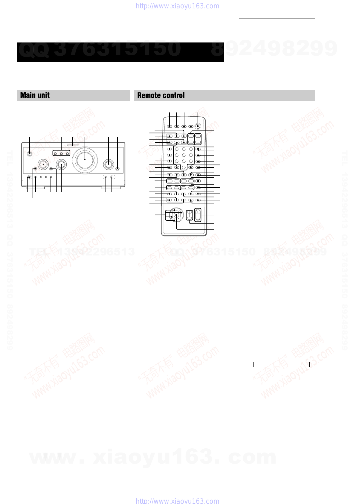
Note: Use following buttons in the test mode.
no mark: Button of amplifier unit (TA-S9D)
*1 : Button of tuner unit (ST-S9)
*2 : Button of DVD/video CD/CD player unit (DVP-S9)
[MCTest Mode]
Enter the MCTest Mode
1. Press the I/1button to turn the power on.
2. While pressing the both [STEREO/MONO] *1and [CINEMA
STUDIO C] buttons, press the [CINEMA STUDIO A] button.
3. “GROOVE” indication blinks on the fluorescent indicator tube
in the midst of MC test mode.
4. This mode has two modes (mode 1/mode 2).
5. To change the modes, press three buttons in the same manner
as entering this mode (step 2). Each time the step 2 operation
is repeated, it changes modes alternately.
6. To distinguish the mode, turn the [VOLUME] knob clockwise
or counterclockwise. Then display is shown as follows.
Mode 1: only “MIN” or “MAX”
Mode 2: “MIN”, “1 to 30” or “MAX”
AMPTest Mode
In the AMP test mode, it operates as follows.
•[VOLUME] knob is turned, it changes display as follows.
Counterclockwise : VOLUME MIN
Clockwise : VOLUME MAX
•[FILE SELECT] knob is turned, it changes speaker output mode
as follows.
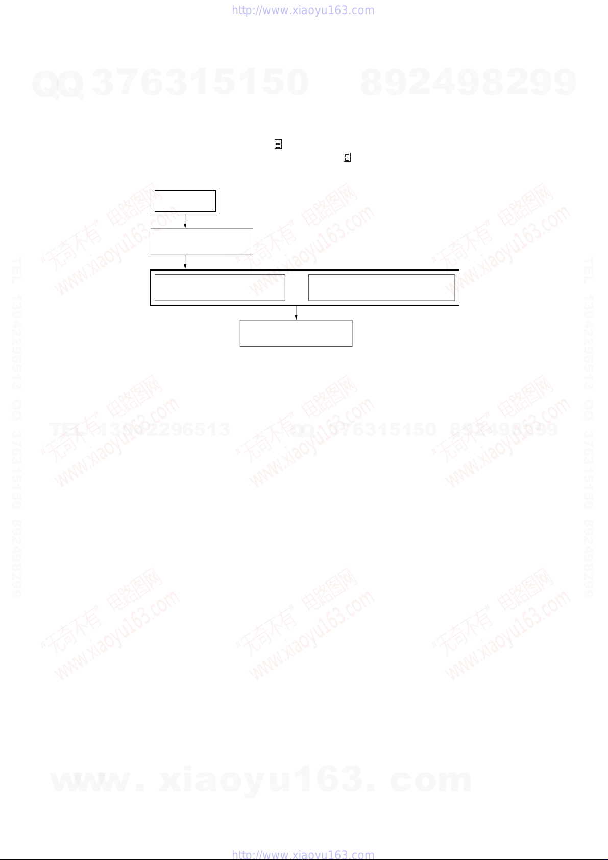
Display of each mode:
Details of each mode:
Mode 1 : L-CH: front L-CH
R-CH: front R-CH
Mode 2 : L-CH: rear L-CH
R-CH: rear R-CH
Mode 3 : L-CH: front L-CH, rear L-CH, center
R-CH: front R-CH, rear R-CH, sub woofer
(no LFE, “EQ” indication does not light up on the fluorescent
indicator tube of tuner unit)
Mode 4 : L-CH: front L-CH, rear L-CH, center
R-CH: front R-CH, rear R-CH, sub woofer
(LFE on, “EQ” indication lights up on the fluorescent indica-
tor tube of tuner unit)
Mode 5 : L-CH: center
R-CH: sub woofer
Releasing the MCTest Mode
To release from this mode, press the I/1button or disconnect the
power cord.
Mode No. Display
1 L: L R: R
2 L: SL R: SR
3 L: LSLC R: RSRW
4 L: LSLC R: RSRW
5 L: C R: W
w
w
w
.
x
i
a
o
y
u
1
6
3
.
c
o
m
Q
Q
3
7
6
3
1
5
1
5
0
9
9
2
8
9
4
2
9
8
T
E
L
1
3
9
4
2
2
9
6
5
1
3
9
9
2
8
9
4
2
9
8
0
5
1
5
1
3
6
7
3
Q
Q
TEL 13942296513 QQ 376315150 892498299
http://www.xiaoyu163.com

10
TA-S9D SECTION 5
DIAGRAMS
5-1. NOTE FOR PRINTED WIRING BOARDS AND SCHEMATIC DIAGRAMS
B
These are omitted.
CE
Q
Note on PrintedWiring Boards:
•X: parts extracted from the component side.
•Y: parts extracted from the conductor side.
•f: internal component.
•: Pattern from the side which enables seeing.
• Indication of transistor.
Note on Schematic Diagram:
• All capacitors are in µF unless otherwise noted. pF: µµF
50 WV or less are not indicated except for electrolytics
and tantalums.
• All resistors are in Ωand 1/4W or less unless otherwise
specified.
•f: internal component.
•2: nonflammable resistor.
•5: fusible resistor.
•C: panel designation.
•A: B+ Line.
•B: B– Line.
• Voltages are dc with respect to ground under no-signal
conditions.
no mark : Power on
( ) : Output is more than 1 W.
• Voltagesare takenwithaVOM (Input impedance 10 MΩ).
Voltage variations may be noted due to normal produc-
tion tolerances.
• Signal path.
F: AUDIO
N: MIC
• Abbreviation
AUS : Australian model
EA : Saudi Arabia model
KR : Korean model
MX : Mexican model
SP : Singapore model
TH :Thai model
Note: The components identified by mark 0or dotted line
with mark 0are critical for safety.
Replace only with part number specified.
• Circuit Boards Location
AC OUTPUT board
SURROUND AMP board
SUB TRANS board
AC INPUT board
RELAY boar
d
FRONT AMP board
PANEL board
w
w
w
.
x
i
a
o
y
u
1
6
3
.
c
o
m
Q
Q
3
7
6
3
1
5
1
5
0
9
9
2
8
9
4
2
9
8
T
E
L
1
3
9
4
2
2
9
6
5
1
3
9
9
2
8
9
4
2
9
8
0
5
1
5
1
3
6
7
3
Q
Q
TEL 13942296513 QQ 376315150 892498299
http://www.xiaoyu163.com

TA-S9D
1111
TM101
TM102
NO109
CN113
JW142
CN103
IC801
CN108
D911
D951
JW49
JW12
C951
C952
C927
C953
R952
IC924
LP902
CN105
CN104
JW150
JW71
C861
C955C912
C911
C956
JW3
R951
JW139
R953
JW143
JW138
R954
EPT901
JW141
D881
R835
R831
R815
JW179
JW108
Q871
Q881
R883
R885
R974
R887
R839
R837
R838
JW39
RY881
JW26
R896
R814
C837
D831
C854
JW163
JW30
R894
JW148
C987
C916
C917
R889
D998
D993
D991
D992
D990
C991
C1100
D923
JW28
Q894
JW187
JW196
R907
C857
JW40
C1103
JW197
R911
R903
Q893
Q897R897C893
R906
R898
Q895
JW2
Q892
R895
JW123
JW95
R804
R807
JW78
Q891
Q896
Q851
JW115
JW113
D994 D995
D997
D996
D924
C994
C925
CN107
JW41
JW116
JW182
JW16
JW15
R908
D980
C1101
R881
C863
JW183
JW38
JW101
CN106
R904
JW177
Q821
C891
R826
R876
JW198
R825
C993
R875
C992
JW20
JW44
R821
C821
JW186
JW17
R910
C871
JW120
R827
R877
R878
D871
R879
R880
C872
JW74
JW18
JW126
JW165
C919
C920
JW180
JW160
JW159
R917
JW155
JW157
R918
JW50
JW161
R914
JW154
R913
R916
JW84
R923
JW158
R919
R920
JW173
JW156
JW195
R921
JW6
JW164
JW190
JW134
JW127
JW105
JW169
JW85
JW104
JW103
R857
JW107
JW100
JW61
R963
R964
JW59
R805
R968
JW48
R851
C852
R852
C962
JW184
Q902
C853
R801
C802
R802
C801
D801
R803
C803
JW42
JW52
C941
C806
C851
C963
R966
C892
R965
D963
JW82
JW87
JW86
JW89
JW90
JW91
JW92
JW93
JW94
JW96
Q883
R973
R809
R972
Q962
R971
R970
R969
Q963
EPT902
JW56
JW176
R925
JW174
JW175
JW172
JW153
JW27
NO101
JW136
JW162
JW109
(AEP, UK)
(EXCEPT AEP, UK)
JW135
JW13
JW73
R871
C1036
JW192
R855
JW68
JW140
Q961
JW72
JW102
C807
JW60
D802
JW133
JW117
JW106
R854
Q903
JW99
R967
JW81
JW66
JW51
JW114
C918
C804
JW131
R924
R926
R830
Q822
D821
JW130
R927
JW128
R856
D851
D973
JW55
C856
D975
R892
Q801
R808
R859
R806
JW65
C811
JW63
JW57
C812
R905
D970
D972
D971
JW185
JW191
D974
JW7
JW10
JW11
JW147
JW9
C964
R853
C862
C865
JW29
JW69
JW152
JW80
JW58
JW19
JW181
JW31
C914
C926
R858
JW8
JW53
JW193
JW67
JW111
R891
JW88
JW146
JW881
JW62
JW149
JW122
JW35
R915
R912
JW170
JW97
JW64
D981
C915
JW151
JW36
JW1
JW54
C864
JW75
C1037
JW83
JW119
JW145
JW132
C924
JW79
D925
JW194
JW21
JW76
JW32
JW70
C1102
JW22
JW178
JW166
JW43
C954
JW45
JW37
R991
JW47
JW46
JW189
D926 R992
JW34
JW201
JW167
C990
JW188
JW98
Q904
JW125
C961
JW168
NO102
JW199
IC310
IC923
CN110
CN111 CN112
JW602
JW603
JW601
R836
C809
C833
R833
L832
C836
C831
C835
L833
R834
C832
C834
L831
R862
C859
C808
L811
L861
R861
C858
R832
R811
Q905
Q906
R961
R960
R962
NO220
NO221
NO225
NO222
EXCEPT
AEP, UK, KR
EXCEPT
AEP, UK, KR
EXCEPT
AEP, UK
EXCEPT
AEP, UK
EXCEPT
AEP, UK
EXCEPT
AEP, UK EXCEPT
AEP, UK
FRONT AMP BOARD
EE
31
31
15
–+
–+
–+
L
L
R
CENTER SPEAKER
IMPEDANCE
USE 8 – 16Ω
REAR SPEAKER
IMPEDANCE
USE 8 – 16Ω
–+
–+
R
FRONT SPEAKER
IMPEDANCE
USE 6 – 16Ω
SYSTEM CONTROL 1
FROM ST-S9
A
SUB TRANS
BOARD
CN903
E
71
13
EE
EE
E
M
M1
(FAN)
E
AC OUTPUT
BOARD
CN915
F
AC OUTPUT
BOARD
CN914
E
EE
E
E
E
E
E
EEE
E
E
(CHASSIS)
13 1 14
H
SURROUND AMP
BOARD
CN1002
J
SURROUND AMP
BOARD
CN1003
1-680-749-
D
PANEL BOARD
CN700
G
AC OUTPUT
BOARD
CN913
16
(CHASSIS)
SYSTEM CONTROL 2
FROM ST-S9
RELAY BOARD
1-680-755-
2
1
21
A
B
C
D
E
F
G
H
I
J
1 2 3 4 5 6 7 8 9 10 11 12 13 14 15 16
(CHASSIS)
CLP1001
11
(12)
11
(22)
(AEP, UK)
11
(13)
11
(23)
(AEP, UK)
D801 H-7
D802 G-7
D821 I-10
D831 D-3
D851 H-7
D871 I-11
D881 D-3
D911 B-10
D923 H-3
D924 G-2
D925 G-2
D926 G-2
D951 B-12
D963 I-6
D970 H-3
D971 I-3
D972 I-4
D973 H-4
D974 H-3
D975 H-3
D980 J-2
D981 F-3
D990 H-2
D991 H-2
D992 H-2
D993 H-2
D994 H-3
D995 H-3
D996 H-3
D997 H-3
IC310 H-10
IC801 H-5
IC923 F-3
IC924 F-2
Q801 H-7
Q821 I-10
Q822 I-10
Q851 G-7
Q871 I-11
Q881 D-3
Q883 D-3
Q891 H-9
Q892 H-9
Ref. No. Location
Ref. No. Location
• Semiconductor Location
Ref. No. Location Ref. No. Location
Q893 H-10
Q894 G-9
Q895 G-9
Q896 H-9
Q897 G-9
Q902 J-3
Q903 J-3
Q904 J-4
Q905 J-5
Q906 J-5
Q961 H-7
Q962 H-4
Q963 G-4
(Page 14) (Page 14)
5-2. PRINTED WIRING BOARDS – FRONT AMP Section – • See page 10 for Circuit Boards Location.
(Page 18)
(Page 18)
(Page
16)
(Page 18)
(Page 18)
w
w
w
.
x
i
a
o
y
u
1
6
3
.
c
o
m
Q
Q
3
7
6
3
1
5
1
5
0
9
9
2
8
9
4
2
9
8
T
E
L
1
3
9
4
2
2
9
6
5
1
3
9
9
2
8
9
4
2
9
8
0
5
1
5
1
3
6
7
3
Q
Q
TEL 13942296513 QQ 376315150 892498299
http://www.xiaoyu163.com

TA-S9D
1313
(Page 12)
(Page 15)
(Page 15)
(Page 19)
(Page 19)
(Page 19)
5-4. SCHEMATIC DIAGRAM – FRONT AMP Section (2/2) –
w
w
w
.
x
i
a
o
y
u
1
6
3
.
c
o
m
Q
Q
3
7
6
3
1
5
1
5
0
9
9
2
8
9
4
2
9
8
T
E
L
1
3
9
4
2
2
9
6
5
1
3
9
9
2
8
9
4
2
9
8
0
5
1
5
1
3
6
7
3
Q
Q
TEL 13942296513 QQ 376315150 892498299
http://www.xiaoyu163.com

TA-S9D
1414
5-6. PRINTED WIRING BOARD – SURROUND AMP Section – • See page 10 for Circuit Boards Location.5-5. IC PIN FUNCTION DESCRIPTION
JW1003
C1087
C1053
JW1002
IC1001
C1052
C1003
C1084
C1054
C1004
JW1015
JW1014
JW1013
JW1012
JW1011
JW1005
C1034
JW1007
R1055
RY1062
R1032
R1031
R1092
C1033
JW1008
R1033
Q1081
D1081
C1086
JW1006
R1088
R1087
R1086
CN1002
D1062
R1062
R1005
R1085
RY1061
JW1001
C1051
R1081
CN1003
R1047
Q1093
R1059
JW1018
R1004
R1051
THP092
R1052
R1003
JW1004
R1008
JW1017
R1089
Q1063
R1063
R1001
Q1061
JW1009
R1009
R1006
R1007
R1056
R1061
JW1019
R1093
JW1010
R1095
R1090
JW1016
R1057
R1058
R1054
R1060
D1002
C1083
R1094
R1082
Q1092
C1056 C1057
C1006
C1007
D1051
D1001
Q1051
Q1001
JW1021
R1010
D1061
R1083
C1001
JW1020
C1081
R1084
R1065
R1053
R1002
C1082
R1069
C1002
C1038
C1039
CLP1000
SURROUND AMP BOARD
1-680-750-
13 1 41
EE
E
E
E
E
E
H
FRONT AMP
BOARD
CN103 J
FRONT AMP
BOARD
CN108
A
B
C
D
1 2 3 4 5
11
(12)
11
(22)
(CHASSIS)
(AEP, UK)
EXCEPT
AEP, UK
• Semiconductor
Location
Ref. No. Location
D1001 B-3
D1002 C-5
D1051 B-3
D1061 B-4
D1062 C-2
D1081 D-2
IC1001 B-1
Q1001 B-3
Q1051 B-3
Q1061 C-5
Q1063 D-5
Q1081 D-1
Q1092 A-4
Q1093 A-4
•FRONT AMP BOARD IC310 PT8300-S (SYSTEM CONTROLLER)
Pin No. Pin Name I/O Description
1 VSS — Ground terminal
2RESET_B I Reset signal input terminal Not used
3CLK I Serial data transfer clock signal input from the tuner unit (ST-S9)
4LATCH I Serial data latch pulse input from the tuner unit (ST-S9)
5LED C O LED drive signal output of the CINEMA STUDIO C indicator (D706) “L”: LED on
6LED B O LED drive signal output of the CINEMA STUDIO B indicator (D705) “L”: LED on
7LED A O LED drive signal output of the CINEMA STUDIO A indicator (D704) “L”: LED on
8LED EQ O LED drive signal output of the EQ indicator (D703) “L”: LED on
9LED SUR O LED drive signal output of the SUR indicator (D702) “L”: LED on
10 LED BLU O LED drive signal output of the MULTI CHANNEL DECODING indicator (D781)
“L”: LED on
11 HP SW I Headphone detection signal input terminal “H”: headphone on
12 PROTECT I Over load detection signal input for speaker output “L”: over load
13 LATCHO O Serial data latch pulse output terminal Not used (open)
14 CLKO O Serial data transfer clock signal output terminal Not used (open)
15 — — Not used (open)
16 — — Not used (fixed at “L”)
17 — — Not used (open)
18 MUTING O Muting on/off control signal output terminal “L”: muting
19 LED PW O LED drive signal output of the I/1indicator (D701) “L”: LED on
20 SUR RY O Relay drive signal output for the surround speaker (rear and center) protection “H”: on
21 F RY O Relay drive signal output for the front speaker protection “H”: on
22 STK PW O Power amplifier on/off selection signal output terminal “L”: standby, “H”: on
23 — — Not used (open)
24 STBY RY O Standby relay drive signal output terminal “L”: standby, “H”: power on
25 DATA OUT O Serial data output to the tuner unit (ST-S9)
26 DATA IN I Serial data input from the tuner unit (ST-S9)
27 PULLUP — Not used (open)
28 VCC — Power supply terminal (+5V)
(Page 11) (Page 11)
w
w
w
.
x
i
a
o
y
u
1
6
3
.
c
o
m
Q
Q
3
7
6
3
1
5
1
5
0
9
9
2
8
9
4
2
9
8
T
E
L
1
3
9
4
2
2
9
6
5
1
3
9
9
2
8
9
4
2
9
8
0
5
1
5
1
3
6
7
3
Q
Q
TEL 13942296513 QQ 376315150 892498299
http://www.xiaoyu163.com

TA-S9D
1616
5-8. PRINTED WIRING BOARDS –CONTROL Section –•See page 10 for Circuit Boards Location.
JW503
R713
S711
S712
S713
S718 S716
J703
S719
S714 S705
R712
S715
D706 D701
S710
D705
CN700
NO780
C735
IC702
NO711
JW522
R710
C710
Q701
R707
R708
JW505
FB704
C712
FB707
NO750
R736
R752
C726
C711
R728
C723
C724
R729
R731
R730
C725
C729
R732
C727
C734
R735
C730
C733
JW508
JW701
C728
C732
C751
C705
CLP702
Q710
R737
C731
R740
R738 R711
CLP701
R739
C702
C701
C703
C704
C706 Q702
JW509
NO710
R733
R715
R709
JW517
R714
R721
R716
R717
R718R719
D704
JW521
R720
JW520
JW524
JW512
JW514
JW510
JW515 JW511
R734
FB703
FB708
FB702
JW502 FB705
FB706
D702
JW518
JW507
JW506
JW705
S723
JW513
JW704
JW501
JW525
D703
JW519
C752
JW516
CLP703
RV761
NO761
D781
R724
NO781
C781
5
4
8
1
2
4
5
3
16
7
R722 R723
S717
7
J702, 703
6
3
2
4
5
1
JW707
PANEL BOARD
E
21
E
FUNCTION
DIGITAL
MIC 2
J702
(CHASSIS)
S703
ROTARY ENCODER
13
VOLUME
S702
ROTARY ENCODER
13
FILE SELECT
EQ
ENTER
SUR
v
V
b
B
EQ ON/OFF SET UP TITLE
PHONES
S701
ROTARY ENCODER
13
DFRONT AMP
BOARD
CN104
(CHASSIS)
CINEMA STUDIO
B
D705, S713
CINEMA
STUDIO
C
D706, S714
CINEMA STUDIO
A
D704, S712
D703, S711
13
13
D702, S710
I/1
D701, S705
1-680-754-
(CHASSIS)
MIC LEVEL
31
31
21
MULTI CHANNEL
DECODING
A
B
C
D
E
F
1 2 3 4 5 6 7 8 9 10 11
DVD
MENU
2
4
3
1
67
5
(EXCEPT AEP, UK)
11
(13)
11
(23)
(AEP, UK)
EXCEPT
AEP, UK
EXCEPT
AEP, UK
24
(AEP, UK)
(Page 11)
D701 B-11
D702 C-10
D703 C-8
D704 B-8
D705 B-7
D706 B-6
D781 A-6
IC702 C-3
Q701 C-6
Q702 C-6
Q710 C-3
•Semiconductor
Location
Ref. No. Location
w
w
w
.
x
i
a
o
y
u
1
6
3
.
c
o
m
Q
Q
3
7
6
3
1
5
1
5
0
9
9
2
8
9
4
2
9
8
T
E
L
1
3
9
4
2
2
9
6
5
1
3
9
9
2
8
9
4
2
9
8
0
5
1
5
1
3
6
7
3
Q
Q
TEL 13942296513 QQ 376315150 892498299
http://www.xiaoyu163.com

TA-S9D
1818
JW906
F913
JW901
F900
LP103
CN913
CN915
F934
JW961
F933 F932 F931 F937
CN914
JW938
JW930
JW922
JW921
JW923
NO921
JW803
JW907
CN903
JW920
LP102 T901
POWER
TRANSFORMER
(SUB)
JW913
CN901
RY901
JW802
JW908
JW904
JW909
D901
Q901
R902
R901
JW801
JW903
JW805
C901
JW902
JW806
JW807
JW808
JW809
JW810
JW811
JW812
JW804
JW905
CN902
F935
F936
VOLTAGE SELECTOR
S901
230 –240V T 220V T120V
NO401
NO400
AC OUTLET
AC OUTPUT BOARDAC INPUT BOARD
3
1
1
6
4
1
F
FRONT AMP
BOARD
NO101
G
FRONT AMP
BOARD
NO102
E
FRONT AMP
BOARD
NO101
1-680-754-
1
2
3
4
1-680-752-
T911
POWER
TRANSFORMER
(MAIN)
2
2341
1
(AC IN)
SUB TRANS BOARD
1
E
5
A
FRONT AMP
BOARD
NO109
1-680-751-
(E, EA, SP)
(E, EA, SP)
(E, EA, SP)
(E, EA, SP)
(AUS)
(AEP, UK, TH, KR, MX, AUS)
(MX)
AEP, UK, TH,
KR, MX, AUS
(AEP, UK, TH, KR, MX, AUS)
(AEP, UK, TH, KR)
(E, EA, SP, MX)
11
(13)
11
(23)
(AEP, UK)
11
(13)
11
(23)
(AEP, UK)
11
(13)
11
(23)
(AEP, UK)
EXCEPT
AEP, UK
EXCEPT
AEP, UK
EXCEPT
AEP, UK
5-10. PRINTED WIRING BOARDS –POWER Section –•See page 10 for Circuit Boards Location.
(Page 11)
(Page 11)
(Page 11)
(Page 11)
w
w
w
.
x
i
a
o
y
u
1
6
3
.
c
o
m
Q
Q
3
7
6
3
1
5
1
5
0
9
9
2
8
9
4
2
9
8
T
E
L
1
3
9
4
2
2
9
6
5
1
3
9
9
2
8
9
4
2
9
8
0
5
1
5
1
3
6
7
3
Q
Q
TEL 13942296513 QQ 376315150 892498299
http://www.xiaoyu163.com

2020
TA-S9D
6-1. CASE SECTION
SECTION 6
EXPLODED VIEWS
The components identified by
mark 0or dotted line with mark
0are critical for safety.
Replace only with part number
specified.
• Items marked “*” are not stocked since they
are seldom required for routine service. Some
delay should be anticipated when ordering
these items.
• The mechanical parts with no reference num-
ber in the exploded views are not supplied.
• Hardware (# mark) list and accessories are
given in the last of the electrical parts list.
NOTE:
• -XX and -X mean standardized parts, so they
may have some difference from the original
one.
• Color Indication of Appearance Parts
Example:
KNOB, BALANCE (WHITE) . . . (RED)
↑↑
Parts Color Cabinet's Color
6-2. FRONT PANEL SECTION
#4
#1
#1
#1
#1
#1
#1
#1
#1
#1
not supplied
Front panel section
2
2
1
5
7
8
4
6
3
not supplied
(EXCEPT AEP, UK)
(included in
FRONT AMP board)
M1
not supplied
not supplied
51
51
53
52
54
59
56
supplied with S702
supplied with S703
supplied with S701
zC
zA
zB
55
56
57
56
56
58
(including zA,
zB, zC)
• Abbreviation
AUS : Australian model
EA : Saudi Arabia model
KR : Korean model
MX : Mexican model
SP : Singapore model
TH : Thailand model
Ref. No. Part No. Description Remark Ref. No. Part No. Description Remark
1 1-773-178-11 WIRE (FLAT TYPE) (23 CORE) (AEP, UK)
1 1-773-210-11 WIRE (FLAT TYPE) (25 CORE)
(EXCEPT AEP, UK)
2 3-363-099-21 SCREW (CASE 3 TP2)
3 4-232-336-11 CASE (AEP, UK)
3 4-232-336-71 CASE (EXCEPT AEP, UK)
4 4-232-348-01 PANEL (DVD), BACK (AEP, UK)
4 4-232-348-41 PANEL (DVD), BACK (SP)
4 4-232-348-51 PANEL (DVD), BACK (EA)
4 4-232-348-61 PANEL (DVD), BACK (AUS)
4 4-232-348-71 PANEL (DVD), BACK (TH)
4 4-232-348-81 PANEL (DVD), BACK (E)
4 4-232-348-91 PANEL (DVD), BACK (MX)
4 4-233-563-01 PANEL (DVD), BACK (KR)
5 1-680-751-11 SUB TRANS BOARD
06 1-526-794-11 OUTLET, AC (AEP, UK, EA, SP, AUS)
06 1-526-882-00 OUTLET, AC (E, TH, MX)
06 1-815-114-11 OUTLET, AC (KR)
7 1-680-755-11 RELAY BOARD
8 3-531-576-11 RIVET (EXCEPT AEP, UK)
M1 1-763-072-11 FAN, D. C.
Ref. No. Part No. Description Remark Ref. No. Part No. Description Remark
51 4-232-342-01 KNOB (FUNC)
52 4-232-338-01 KNOB (VOL)
53 X-4953-682-1 PANEL ASSY, FRONT (AEP, UK)
53 X-4953-683-1 PANEL ASSY, FRONT (EXCEPT AEP, UK)
54 4-232-341-01 SHEET (VOL)
55 4-232-343-01 BUTTON (ENTER)
56 4-951-620-01 SCREW (2.6X8), +BVTP
57 4-232-344-01 INDICATOR (BLUE)
58 A-4727-056-A PANEL BOARD, COMPLETE (TH)
58 A-4727-061-A PANEL BOARD, COMPLETE (AEP, UK)
58 A-4727-073-A PANEL BOARD, COMPLETE
(E, EA, SP, KR, MX, AUS)
59 4-232-340-01 KNOB (MIC) (EXCEPT AEP, UK)
w
w
w
.
x
i
a
o
y
u
1
6
3
.
c
o
m
Q
Q
3
7
6
3
1
5
1
5
0
9
9
2
8
9
4
2
9
8
T
E
L
1
3
9
4
2
2
9
6
5
1
3
9
9
2
8
9
4
2
9
8
0
5
1
5
1
3
6
7
3
Q
Q
TEL 13942296513 QQ 376315150 892498299
http://www.xiaoyu163.com
Other manuals for TA-S9D
1
Table of contents
Other Sony Amplifier manuals

Sony
Sony TA-F161R User manual

Sony
Sony XM-404EQX User manual

Sony
Sony TA-A400 User manual

Sony
Sony PHA-2 User manual

Sony
Sony EXM-302 User manual

Sony
Sony XM-2165GTX Marketing Specifications User manual

Sony
Sony TA-S9D User manual

Sony
Sony UDA-1 Operating instructions

Sony
Sony TA-V901 User manual

Sony
Sony XM-GTR2202 User manual