Sony DSR200P User manual

DSR-200P CE 3-858-622-12(1). E
3-858-622-12 (1)
©1996 by Sony Corporation
DSR-200P
Operating Instructions
Before operating the unit, please read this manual thoroughly,
and retain it for future reference.
Digital Camcorder
,,
,,
@@
@@
ÀÀ
ÀÀ

2
DSR-200P CE 3-858-622-12(1). E
WARNING
To prevent fire or shock hazard, do not expose the unit to rain or moisture.
To avoid electrical shock, do not open the cabinet.
Refer servicing to qualified personnel only.
Voor de klanten in Nederland
Bij dit produkt zijn battarijen geleverd. Wanneer deze leeg zijn, moet u ze niet
weggooien maar inleveren als KCA.

3
DSR-200P CE 3-858-622-12(1). E
Table of contents
Before you begin
Using this manual ................................... 4
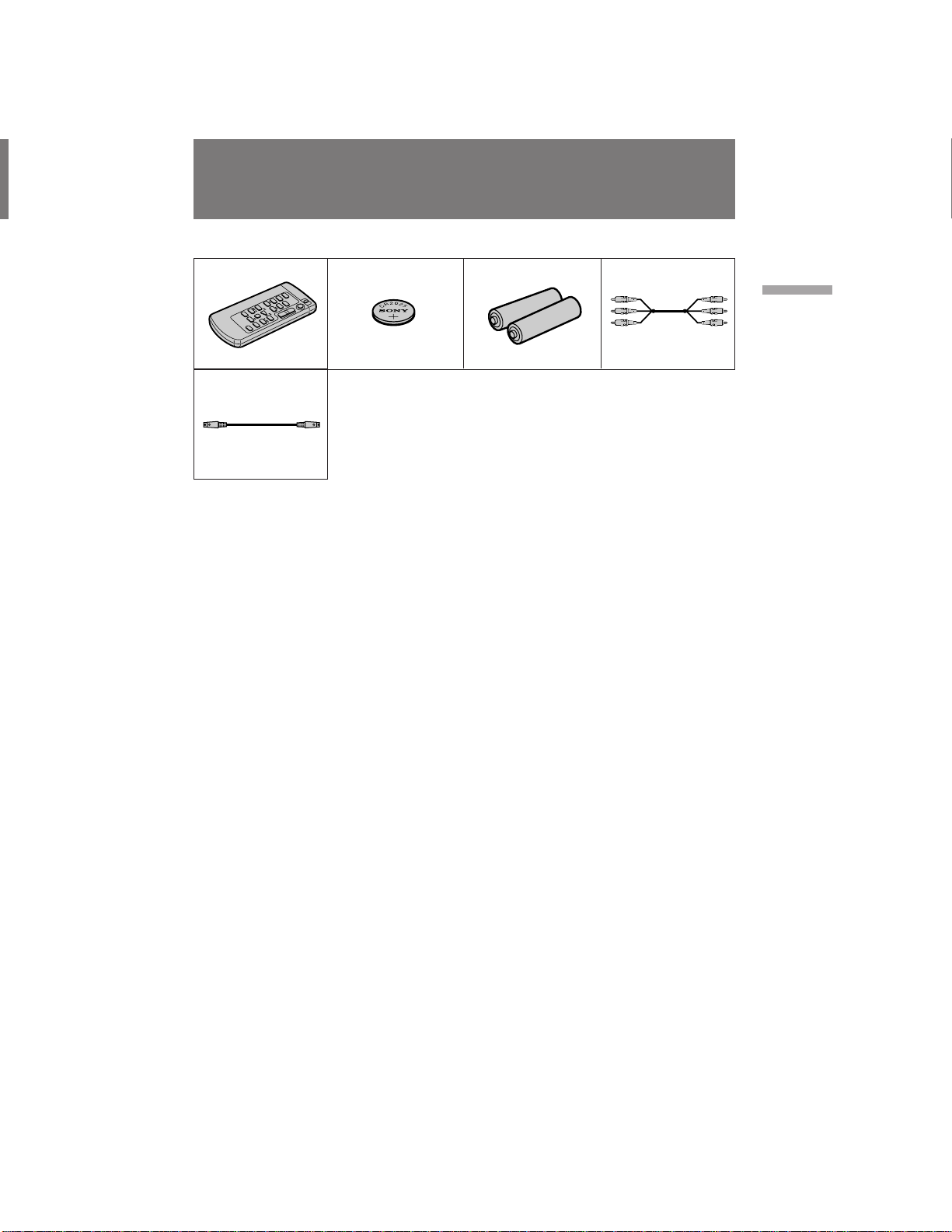
Checking supplied accessories .............. 5
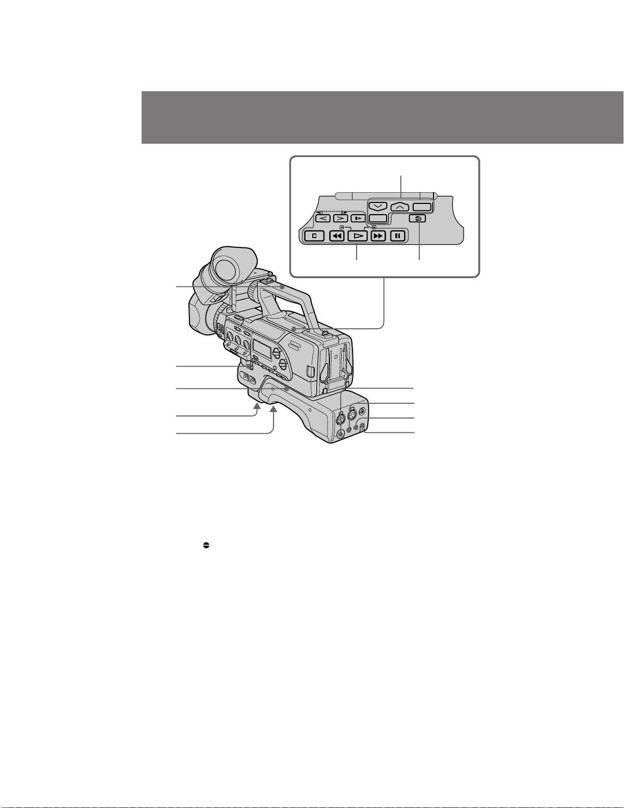
Identifying the parts................................ 6
Attaching optional accessories ............ 17
Getting started
Attaching the viewfinder ..................... 20
Charging and installing the
battery pack .................................... 21
Inserting a cassette ................................ 24
Basic operations
Camera recording.................................. 26
Using the zoom feature .................. 30
Hints for better shooting ...................... 31
Checking the recorded picture ............ 33
Connections for playback ..................... 34
Playing back a tape ............................... 36
Advanced operations
Using alternative power sources ......... 38
Changing the mode settings ................ 40
– for camera recording –
Fade-in and fade-out ............................. 43
Overlapping two pictures .................... 44
Using the wide mode function ............ 45
Photo recording ..................................... 46
Interval recording.................................. 47
Cut recording ......................................... 48
– for manual adjustment –
Selecting automatic or manual mode . 49
Focusing manually ................................ 51
Adjusting the aperture.......................... 54
Adjusting the shutter speed ................. 55
Adjusting the gain ................................. 58
Adjusting the white balance ................ 60
Using the ND filter ................................ 63
Using the zebra pattern ........................ 64
Adjusting the recording sound............ 65
Releasing the STEADY SHOT
function ............................................ 68
Making a custom preset........................ 69
– for editing/playback –
Searching the recorded picture............ 71
Displaying recording data.................... 73
Editing onto another tape..................... 74
Audio dubbing ...................................... 76
Additional information
Changing the lithium battery in the
digital camcorder ............................ 78
Resetting the date and time.................. 80
Compatibility of DVCAM and DV
formats ............................................. 81
Notes on video cassettes ....................... 83
Tips for using the battery pack ............84
Maintenance information and
precautions ...................................... 86
Using your digital camcorder
abroad............................................... 89
Trouble check......................................... 90
Specifications ......................................... 94
Warning indicators................................ 95
Index ........................................ Back cover

4
DSR-200P CE 3-858-622-12(1). E
As you read through this manual, buttons and settings on the digital camcorder are
shown in capital letters.
e.g. Set the POWER switch to ON.
As indicated with ≥in the illustrations, you can hear the beep sound to confirm your
operation.
Note on TV colour systems
TV colour systems differ from country to country. To view your recordings on a TV,
you need a PAL system-based TV.
Precaution on copyright
Television programmes, films, video tapes, and other materials may be copyrighted.
Unauthorized recording of such materials may be contrary to the provision of the
copyright laws.
Precautions on digital camcorder care
• Do not let sand get into the digital camcorder. When you use the digital
camcorder on a sandy beach or in a dusty place, protect it from the sand or dust.
Sand or dust may cause the unit to malfunction, and sometimes this
malfunction cannot be repaired [a].
• Do not let the digital camcorder get wet. Keep the digital camcorder away from
rain and sea water. Letting the digital camcorder get wet may cause the unit to
malfunction, and sometimes this malfunction cannot be repaired [b].
• Never leave the digital camcorder exposed to temperatures above 60°C (140°F),
such as in a car parked in the sun or under direct sunlight [c].
Before you begin
Using this manual
[b] [c][a]
Contents of the recording cannot be compensated if
recording or playback is not made due to a malfunction of
the digital camcorder, video tape, etc.

5
DSR-200P CE 3-858-622-12(1). E
Before you begin
Check that the following accessories are supplied with your digital camcorder.
Checking supplied accessories
1234
5
1Wireless Remote Commander (1) (p.11)
2CR2025 Lithium Battery(1) (p. 78)
The lithium battery is already installed in
your digital camcorder.
3R6 (size AA) battery for Remote
Commander(2) (p. 12)
4A/V connecting cable(1) (p. 34)
5S video cable(1) (p. 34)

DSR-200P CE 3-858-622-12(1). E
6
Identifying the parts
1Stopper (p. 20)
Lift up and hold to remove the viewfinder.
2Viewfinder(p. 20, 27, 87)
3Viewfinder adjustment ring(p. 27)
4PUSH button (p. 87)
Press and hold to raise the eyecup.
5Viewfinder release lever(p. 32)
Push forward to move the position of the
viewfinder front and back.
6Focus ring (p. 52)
7FOCUS switch (p. 52)
Set to select auto or manual focus.
8ND FILTER switch (p. 63)
9PUSH AUTO button (p. 52)
Push to use automatic focus momentarily.
!ºPOWER switch (p. 26)
!¡CAMCORDER/PLAYERswitch (p. 26)
!™ Accessory shoe (p. 46)
!£Hook for shoulder strap(p. 16)
!¢Cassette compartment and cassette
compartment cover (p. 24)
!∞Hook for shoulder strap(p. 16)
!§EJECT 6button(p. 25)
Press to eject the cassette.
!¶Speaker (p. 28)
!•Battery mounting surface(p. 23)
!ªBATT lever (p. 23)
Press and hold to release the batteries.
@ºVIDEO OUT jack (for BNC type plug)
(p. 35)
@¡AUDIO IN jacks (p. 65)
Input external audio/microphone signals.
1
2
3
9
8
!¡
!™
!£
!§
!¶
@¡
!¢
!ª
!∞
!•
6
4
5
7
0
@º

7
DSR-200P CE 3-858-622-12(1). E
Before you begin
@™ Microphone holder attaching point
(p. 18)
@£ TALLY lamp (p. 27)
Lights while recording and when the
battery becomes low.
@¢ CONTR knob (p. 27)
Turn to adjust the viewfinder’s contrast.
@∞ TALLY switch (p. 27)
Set to select TALLY lamp ON/OFF.
@§ Front Remote Commander sensor
(p. 14)
@¶ Grip (p. 31)
@• Grip strap (p. 31)
@ªLens hood
You can attach a wide teleconversion lens
(not supplied) by removing the lens hood.
#ºLens hood cap (p. 26)
#¡BRIGHT knob (p. 27)
Turn to adjust the viewfinder’s brightness.
#™ EDITSEARCH button (p. 33)
#£Front START/STOP button (p. 31)
#¢FADER/OVERLAP button (p. 43, 44)
#∞ WHITE BALANCE ∑(one-push white
balance) button (p. 60)
#§CP CHECK button (p. 70)
Press to check the custom preset settings.
@§
@∞
@ª
#™
#º
@™
@£
@¢
@¶
@•
#¡
#£
#¢
#∞
#§

DSR-200P CE 3-858-622-12(1). E
8
Identifying the parts
$•
%¢
%∞
%•
%§
%¶
$ª
%º
%™
%£
#•
#¶
#ª
$º
$¡
$§
$¶
%¡
$¢
$∞
$™
$£
#¶ Eyecup
#• VIEW FINDER jack (p. 20)
#ªS VIDEO OUT jack (p. 34)
$ºRFU DC OUT jack (p. 35)
$¡DV OUT jack (p. 74)
Connect DV products using the connecting
DV cable.
$™ CH-1 LINE/MIC switch(p. 65)
Set to change the audio source using a CH-
1 input.
$£CH-1 ATT (REAR) switch (p. 67)
Set ON to attenuate the CH-1 input
microphone level.
$¢CH-2 LINE/MIC switch(p. 65)
Set to change the audio source using CH-2
input.
$∞ CH-2 ATT (REAR) switch (p. 67)
Set ON to attenuate the CH-2 input
microphone level.
$§MIC (PLUG IN POWER) jack (p. 28)
Connect an external mini jack type
microphone (not supplied). This jack also
accepts a “plug-in-power” microphone.
When using this jack, set LINE/MIC to
MIC FRONT.
$¶DIRECTIONSELECTswitch (p.28)
Set to change the directionality of the built-
in microphone.
$•Built-in microphone (p. 65)
$ªMicrophone wind screen screw
Loosen to remove wind screen.
%ºMIC switch (p. 67)
Set ATT to attenuate the built-in
microphone and external microphone
connected to MIC (PLUG IN POWER) level.
%¡Lens hood screw
%™ Power zoom button(p. 30)
%£ PHOTO button (p. 46)
Press to shoot in photo mode.
%¢ STANDBY(LOCK/STANDBY/PHOTO
STANDBY) switch (p. 26)
%∞ START/STOP button (p. 26)
%§ BUILT-IN MIC switch (p. 67)
If recording when there is a loud wind using
the built-in microphone, set to WIND.
%¶ AUDIO OUT/VIDEO OUT jacks (p. 34)
%• DC IN jack (p. 38)

9
DSR-200P CE 3-858-622-12(1). E
Before you begin
%ª ^º ^™ ^¢ ^∞ ^§ ^¶^¡ ^£
&º&¡&™&£ ^ª ^•
%ªSHUTTER SPEEDdial andAUTO/MANUAL
switch (p. 55)
^ºDIGITAL MODE switch (p. 30, 44)
Set to select the OVERLAP, 16:9 WIDE or
D ZOOM mode.
^¡GAIN dial and AGC/MANUAL switch
(p. 58)
^™ STEADY SHOT switch (p. 68)
^£WHT BAL (white balance) dial and ATW/
MANUAL switch (p. 60, 61)
^¢DISPLAY LIGHT switch (for display
window)
Use to set the display back light switch
ON/OFF.
^∞ Display window (p. 16)
^§PEAK indicators (L and R) (p. 66)
^¶ RECLEVELdials (p.66)
^• RECLEVEL switches (p.66)
^ªTCRESETbutton
Set time code to 0:00:00:00 when you want
to reset the time code while shooting.
&ºAUDIO MODE switch (p. 29)
Set to select Fs 32k (12 bit) or Fs 48k (16 bit)
audio recording mode.
&¡SPEAKER switch (p. 28)
&™ AUDIO MONITOR switch (p. 66)
&£ AUTO LOCK switch (p. 26)
Set to turn automatic settings for aperture,
shutter speed, gain, and white balance ON/
OFF.

DSR-200P CE 3-858-622-12(1). E
10
Identifying the parts
&ª
*º
*™ *¡
*£
*¢
*∞
*§
&¢
&§
&¶
&•
&∞
&¢ Carrying handle
&∞ IRIS dial and AUTO/MANUAL switch
(p. 54)
&§ Shoulder pad
&¶ Tripod receptacle (p. 17)
&• Lithium battery cover(p. 79)
&ªCover for menu and video controls
*ºMenu buttons (p. 40)
*¡AUDIO DUB button (p. 77)
*™ Video controls (p. 36)
πSTOP button (stop)
0REW button (rewind)
·PLAY button (playback)
)FF button (fast forward)
PPAUSE button (pause)
&SLOW button (slow speed playback)
'/7FRAME button (direction select/
frame-by-frame)
*£MONITOR LEVEL dial (p. 28)
Turn to adjust the volume level of the
headphones and built-in speaker.
*¢2(headphones) jack (p. 28)
*∞lLANC jack
lstands for Local Application Control Bus
System. The lcontrol jack is used for
controlling the tape transport of video
equipment and peripherals connected to it.
This jack has the same function as the jack
indicated as CONTROL L or REMOTE.
*§Tally lamp/Rear Remote Commander
sensor (p. 27, 14)

11
DSR-200P CE 3-858-622-12(1). E
Before you begin
2
1
3
4
5
7
8
9
!¡
!º
6
Remote Commander
The buttons that have the same name on the Remote Commander as on the digital
camcorder function identically.
1Transmitter
Point toward the remote sensor to control
the digital camcorder after turning on the
digital camcorder.
2PHOTO button(p.46)
3DISPLAY button(p. 36)
4SEARCH MODE/ =/+buttons(p. 71)
Press SEARCH MODE to select date search
or photo search.
5AUDIO DUB button(p. 77)
6ZERO SET MEMORY button
This button does not function.
7VTR4/ID/VTR2 switch(p. 13)
Select VTR4 or ID, the same setting as
COMMANDER in the menu system.
The VTR2 position does not function on
this digital camcorder.
8START/STOP button
9Zoom button
The zooming speed is unchangeable by the
Remote Commander.
!ºDATA CODE button(p. 73)
!¡Video control buttons

12
DSR-200P CE 3-858-622-12(1). E
To prepare the Remote Commander
To use the Remote Commander, you must insert two R6 (size AA) batteries. Use the
supplied R6 (size AA) batteries.
(1)Remove the battery cover from the Remote Commander.
(2)Insert both of the R6 (size AA) batteries with correct polarity.
(3)Put the battery cover back onto the Remote Commander.
Note on battery life
The batteries for the Remote Commander last about 6 months under normal operation.
When the batteries become weak or dead, the Remote Commander does not work.
To avoid damage from possible battery leakage
Remove the batteries when you will not use the Remote Commander for a long time.
To use the Remote Commander
Make sure that the COMMANDER is set to VTR4/ID in the menu system on the digital
camcorder.
Identifying the parts

13
DSR-200P CE 3-858-622-12(1). E
Before you begin
About the ID of the Remote Commander
You can avoid having the digital camcorder accidentally respond to signals from other
remote commanders by setting the VTR4/ID/VTR2 switch to ID. Use the supplied
Remote Commander when you set the switch to ID. When you use the Remote
Commander for the first time, register the ID following the procedure below. Once you
have registered the ID, you do not need to do so again.
(1)Install a power source, open the cover, then press MENU to display the menu in the
viewfinder.
(2)Press or to select COMMANDER, then press EXECUTE.
(3)Press or to select ID SET.
(4)Set VTR4/ID/VTR2 on the Remote Commander to ID.
(5)Point the Remote Commander at the Remote Commander sensor on the digital
camcorder and press pSTOP on the Remote Commander.
After the beep sound, the ID of the Remote Commander is registered, and the
COMMANDER is set to ID in the menu system.
(6)Press MENU to erase the menu display.
MENU
D ZOOM OFF
16 : 9 WIDE
ZEBRA
COMMANDER
BEEP
FRAME REC
INT REC
[ MENU ] : END
MENU
COMMANDER VTR4
OFF
ID
ID SET
[ MENU ] : END
MENU
COMMANDER VTR4
OFF
ID
ID SET
COMMANDER [ STOP ] : ID SET
MENU
ID
VTR 4
STOP 4
1
5
2
3
VTR 2

14
DSR-200P CE 3-858-622-12(1). E
Remote control direction
Aim the Remote Commander at either of the two remote commander sensors.
The range of the Remote Commander is about 5 m (about 16 feet) indoors. Use the
Remote Commander as close to flat as possible, otherwise it may not work.
Notes on the Remote Commander
• Keep the Remote Commander sensor away from strong light sources such as direct
sunlight or illumination. Otherwise, the remote control may not be effective.
• Be sure that there is no obstacle between the Remote Commander sensor on the
digital camcorder and the Remote Commander.
• When you operate this digital camcorder using the supplied Remote Commander,
other video equipment may work in error. In this case, set the commander modes of
this digital camcorder to ID.
• You do not need to store the ID again, after having done so once. Set COMMANDER
to ID in the menu system, and set the VTR4/ID/VTR2 switch on the Remote
Commander to ID.
• The stored ID is not erased even if you replace the lithium battery.
Identifying the parts
Remote Commandersensors

15
DSR-200P CE 3-858-622-12(1). E
Before you begin
1Manual focusing indicator(p. 53)
appears when focusing far, appears
when focusing close.
2ND filter indicator(p. 63)
3White balance indicator(p. 60)
4Steady shot indicator(p. 68)
5Zoom indicator(p. 30, 52)
6Manual setting data/wide mode/fader or
overlap/AGC LMT indicators(p. 54, 55, 58,
45, 43, 44)
If not set, the indicator disappears, and all
indicators below rise 1 row.
7Data code indicators(p. 73)
8Lithium battery indicator(p. 78)
9Recording/battery lamp(p. 26)
In the viewfinder
4000
F2.8
0
dB
16 : 9 WIDE
FADER
T
W
0 :13 : 46:05
1
4
3
5
6
7
8
2
I
170 m i n
48k
PHOTO
CP DV STBY
ONND
!£
9
!¡
0
!∞
!§
!¢
!•
!¶
!™
0Custom preset indicator(p. 69)
!¡ DV indicator(p. 37)
During DV-formatted tapes playback, this
indicator appears.
!™ Video control mode(p. 26)
!£ Time code
!¢ Remaining tape indicator
!∞ Audio mode indicator(p. 29)
!§ INTERVAL/FRAMEREC/PHOTO/
C MEMORY/date search/Photo search
indicator (p. 47, 48, 46, 25, 71)
!¶ Remaining battery indicator(p. 84)
!• Warning indicators(p. 95)

16
DSR-200P CE 3-858-622-12(1). E
In the display window
Identifying the parts
DVCAM
HMSF
min
F
143562789
Attaching the shoulder strap
Attach the shoulder strap (not supplied) to the hooks for the shoulder strap.
1 2 3
1Time code
2Warning indicators(p. 95)
3DVCAM indicator
Lights up when using a DVCAM-formatted
tape.
4Flash indicator
5Date/aperture indicator(p. 80, 54)
6Remaining battery indicator(p. 84)
7Time indicator
8Remaining tape indicators
9Audio level indicators(p. 66)

17
DSR-200P CE 3-858-622-12(1). E
Before you begin
Attaching optional accessories
Attaching digital camcorder to the tripod adaptor
Use the VCT-U14 tripod adaptor (not supplied). Once the tripod adaptor has been
attached to the tripod stand, then you may attach the digital camcorder.
(1)Attach the tripod adaptor to the tripod.
(2)Attach the digital camcorder to the tripod stand’s grooved surface [a], and slide it
forward until you hear a click.
Select a balanced and secure position for the tripod stand.
12
[a]
Note on tripod attachment pin
If the tripod attachment pin [c]does not return after removing the digital camcorder,
press the red button on the release lever, and while holding, move the lever in the
direction of the arrow and the pin returns to its original position. If the pin is not set in
its original position you will not be able to reattach the digital camcorder.
[c]
To remove the digital camcorder from the tripod
Press the red button on the release lever [b], and while holding, move the lever in the
direction of the arrow to release the lock.
[b]

18
DSR-200P CE 3-858-622-12(1). E
Attaching the external microphone with XLR connector
When using the ECM-672 external microphone (not supplied), attach the CAC-12
microphone holder (not supplied) to the digital camcorder.
(1)Remove the screws from the top of the viewfinder.
Remove the spacer from the screws. They are unnecessary when attaching the
microphone holder.
(2)Attach the microphone holder with the washers supplied with the microphone
holder and the screws removed in step (1).
(3)Loosen the microphone holder screw and open the cover.
(4)Place the microphone into the holder, close the cover, and tighten the screw.
(5)Connect the microphone to the AUDIO IN jacks of the digital camcorder, then set
LINE/MIC to MIC REAR.
Attaching optional accessories
13
2
5
4
AUDIO IN
LINE/
MIC

19
DSR-200P CE 3-858-622-12(1). E
Before you begin
Attaching the battery adaptor
The NPA-10000 battery adaptor (not supplied), can hold up to 3 battery packs NP-F930,
NP-F730 or NP-720 (not supplied). Attach the adaptor to the digital camcorder.
(1)Release the lock and open the cover.
(2)Insert the battery packs in the direction of the zmark on the battery packs.
(3)Close the cover, then lock.
(4)Attach the battery adaptor to the digital camcorder by sliding until it clicks.
1234
1
3
2
1
2
3
To remove battery adaptor [a]
While pressing BATT, lift the battery adaptor out in the direction of the arrow.
To remove the battery pack [b]
Open the cover, press and hold the release lever, and slide the battery pack out in the
direction of the arrow.
Checking the remaining battery indicator [c]
Press CHECK on the battery adaptor.
If there is still power left in the batteries, the lamp [d]lights.
[c][a] BATT [b]
[d]
CHECK

20
DSR-200PCE3-858-622-12(1).E
[a]
Beforeusingthedigitalcamcorder,attachtheviewfinder.
(1)Loosentheviewfinderreleasering.
(2)Slidetheviewfinderontotheattachingplate.
(3)Adjustthepositionoftheviewfinder,thentightentheviewfinderreleasering.
(4)Attachthe8pinconnectortotheVIEWFINDERjackonthedigitalcamcorder.
Matchridgeon8pinconnectortotheridgeonthejack.
1
3
Note on the VIEW FINDER jack
ThisVIEWFINDERjackisspeciallydesignedforthisdigitalcamcorder.Donotconnect
anythingelsetothisVIEWFINDERjack.
To remove the viewfinder
Loosenviewfinderreleasering.Thenpullstopper [a]up,andwhileholding,slide
viewfinderofftheattachingplate.
Getting started
Attaching the viewfinder
2
4
VIEW
FINDER
Table of contents
Other Sony Camcorder manuals

Sony
Sony Handycam HDR-XR260V User manual

Sony
Sony DCR- User manual

Sony
Sony HXR-NX70C User manual

Sony
Sony CCD-TRV30 - Video Camera Recorder 8mm User manual

Sony
Sony HDR-MV1 User manual

Sony
Sony Handycam CCD-F302 User manual

Sony
Sony HDR-GW77V Training manual

Sony
Sony Digital Handycam DCR-TRV203 User manual

Sony
Sony Handycam DCR-TRV60 User manual

Sony
Sony Handycam DCR-SR82 User guide

Sony
Sony Handycam DCR-SR10E User manual

Sony
Sony HVR-Z7U User manual

Sony
Sony PMW-F55 User manual

Sony
Sony HDCAM HDW-750 User manual

Sony
Sony XDCAM PDW-850 User manual

Sony
Sony CCD-TRV19 User manual

Sony
Sony SSC-MX13V User manual

Sony
Sony Handycam DCR-PC101E User manual

Sony
Sony CVX-V3 User manual

Sony
Sony PDW-680 User manual