manuals.online logo
Brands
  1. Home
  2. •
  3. Brands
  4. •
  5. Sony
  6. •
  7. Camcorder
  8. •
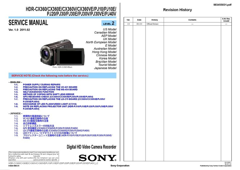
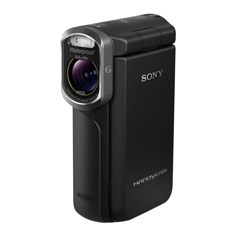
  9. Sony HDR-CX360 User manual

Sony HDR-CX360 User manual

Other manuals for HDR-CX360

4

This manual suits for next models

11

Other Sony Camcorder manuals

Sony Handycam DCR-SR82 User guide

Sony

Sony Handycam DCR-SR82 User guide

Sony DCR-PC115 User manual

Sony

Sony DCR-PC115 User manual

Sony DVW-970/970P User manual

Sony

Sony DVW-970/970P User manual

Sony SLV-E830B User manual

Sony

Sony SLV-E830B User manual

Sony Handycam HDR-XR160 User manual

Sony

Sony Handycam HDR-XR160 User manual

Sony FDR-X1000V User manual

Sony

Sony FDR-X1000V User manual

Sony Handycam CCD-FX710 User manual

Sony

Sony Handycam CCD-FX710 User manual

Sony Handycam HDR-FX1000 User manual

Sony

Sony Handycam HDR-FX1000 User manual

Sony NXCAM NEX-FS700 Manual

Sony

Sony NXCAM NEX-FS700 Manual

Sony XDCAM PMW-1000 User manual

Sony

Sony XDCAM PMW-1000 User manual

Sony CCD-TRV49E User manual

Sony

Sony CCD-TRV49E User manual

Sony Handycam HDR-CX160E User manual

Sony

Sony Handycam HDR-CX160E User manual

Sony DVD608 User manual

Sony

Sony DVD608 User manual

Sony Handycam DCR-TRV380 User manual

Sony

Sony Handycam DCR-TRV380 User manual

Sony Handycam DCR-HC90 User manual

Sony

Sony Handycam DCR-HC90 User manual

Sony HDR-CX720V User manual

Sony

Sony HDR-CX720V User manual

Sony TRV38 - MiniDV 1Megapixel Camcorder User manual

Sony

Sony TRV38 - MiniDV 1Megapixel Camcorder User manual

Sony Handycam DCR-SR50E User manual

Sony

Sony Handycam DCR-SR50E User manual

Sony HDR-AS10 User manual

Sony

Sony HDR-AS10 User manual

Sony Handycam DCR-PC1E User manual

Sony

Sony Handycam DCR-PC1E User manual

Sony Handycam DCR-TRV950 User manual

Sony

Sony Handycam DCR-TRV950 User manual

Sony PMW-350K Owner's manual

Sony

Sony PMW-350K Owner's manual

Sony DCR-PC109 - Digital Handycam Camcorder User manual

Sony

Sony DCR-PC109 - Digital Handycam Camcorder User manual

Sony Handycam HDR-SR10 User manual

Sony

Sony Handycam HDR-SR10 User manual

Popular Camcorder manuals by other brands

Vivitar DVR 830XHD owner's manual

Vivitar

Vivitar DVR 830XHD owner's manual

Panasonic HX-WA20PP Service manual

Panasonic

Panasonic HX-WA20PP Service manual

Canon FS1 instruction manual

Canon

Canon FS1 instruction manual

Sharp VL-H400S Operation manual

Sharp

Sharp VL-H400S Operation manual

Panasonic AJ-D900WAP operating instructions

Panasonic

Panasonic AJ-D900WAP operating instructions

Samsung VP-D6550 Owner's instruction book

Samsung

Samsung VP-D6550 Owner's instruction book

Naxa NDC-402 instruction manual

Naxa

Naxa NDC-402 instruction manual

LG L320-BN owner's manual

LG

LG L320-BN owner's manual

Vivitar DVR 865HD user manual

Vivitar

Vivitar DVR 865HD user manual

Toshiba CAMILEO Z100 user guide

Toshiba

Toshiba CAMILEO Z100 user guide

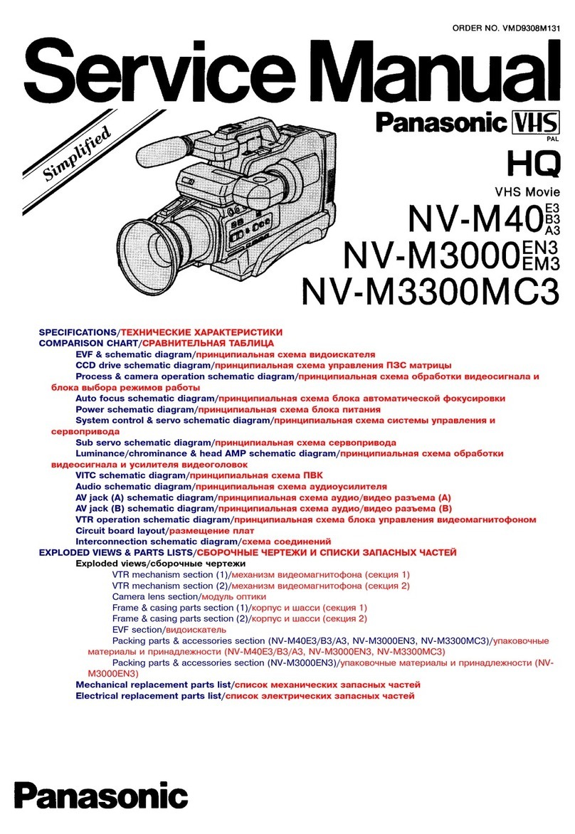
Panasonic NV-VS40B operating instructions

Panasonic

Panasonic NV-VS40B operating instructions

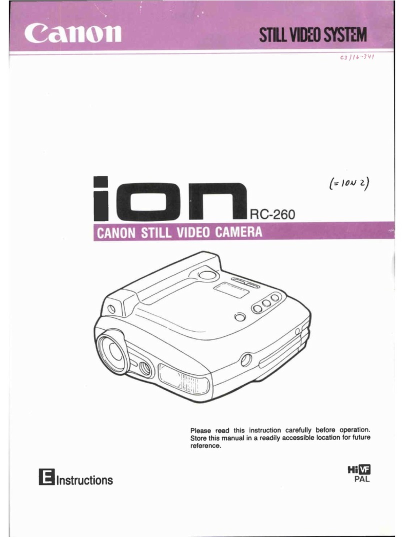
Canon RC 260 instructions

Canon

Canon RC 260 instructions

Brinno TimeLapse TLC200 user manual

Brinno

Brinno TimeLapse TLC200 user manual

JVC GR-SXM68AC Schematic diagram

JVC

JVC GR-SXM68AC Schematic diagram

MYDLINK DCS-6100LH Quick installation guide

MYDLINK

MYDLINK DCS-6100LH Quick installation guide

SECURECOM V-5014B installation guide

SECURECOM

SECURECOM V-5014B installation guide

JVC AA-V15EG instruction manual

JVC

JVC AA-V15EG instruction manual

Canon LEGRIA HV40 instruction manual

Canon

Canon LEGRIA HV40 instruction manual

manuals.online logo
manuals.online logoBrands
  • About & Mission
  • Contact us
  • Privacy Policy
  • Terms and Conditions

Copyright 2025 Manuals.Online. All Rights Reserved.

SERVICE MANUAL
HDR-CX360/CX360E/CX360V/CX360VE/PJ10/PJ10E/PJ20/PJ30/PJ30E/PJ30V/PJ30VE/PJ40V_L2
SERVICE NOTE (Check the following note before the service.)
Revision History
Published by Sony Techno Create Corporation
Sony Corporation
LEVEL 2
983455037.pdf
Ver. 1.6 2012.08
Digital HD Video Camera Recorder
The components identified by mark
0or dotted line with mark 0are
critical for safety.
Replace only with part number
specified.
Les composants identifiés par une
marque 0sont critiques pour la
sécurité.
Ne les remplacer que par une
pièce portant le numéro spécifié.
9-834-550-37
US Model
Canadian Model
AEP Model
UK Model
North European Model
E Model
Australian Model
Hong Kong Model
Chinese Model
Korea Model
Brazilian Model
Tourist Model
Japanese Model
Ver. Date History Contents S.M. Rev.
issued
1.0 2011.02 Official Release — —
1.1 2011.08 Revised-1
(A1 11-163)
• Revision of SERVICE NOTE.
Page 1-1, 1-5
Yes
1.2 2011.10 Revised-2
(A2 11-229)
• Correction of EXPLODED VIEWS.
Page 2-6
Yes
1.3 2011.11 Revised-3
(A3 11-287)
・Correction of EXPLODED VIEWS.
Page 2-14
Yes
1.4 2011.12 Revised-4
(A4 11-316)
・Correction of EXPLODED VIEWS.
Page 2-6
Yes
1.5 2012.03 Revised-5
(A5 11-481)
・Correction of EXPLODED VIEWS.
Page 2-9
Yes
1.6 2012.08 Revised-6
(A6 12-188)
• Change of REPAIR PARTS LIST.
Page 2-12
Yes
2012H08-1
© 2012.08
HDR-CX360/CX360E/CX360V/CX360VE/PJ10/PJ10E/
PJ20/PJ30/PJ30E/PJ30V/PJ30VE/PJ40V
– ENGLISH –
1-1. POWER SUPPLY DURING REPAIRS
1-2. PRECAUTION ON REPLACING THE VC-621 BOARD
1-3. PRECAUTION ON REPLACING THE MS-454 BOARD
1-4. SELF-DIAGNOSIS FUNCTION
1-5. METHOD OF COPING WITH SHIFT LENS ERROR
1-6. GPS RECEIVING CHECK (CX360V/CX360VE/PJ30V/PJ30VE/PJ40V)
1-7. PRECAUTION ON REPLACING THE LD-279 BOARD (CX360V/CX360VE/PJ30V/
PJ30VE/PJ40V)
1-8. DISCHARGE OF LED FLASH/VIDEO LIGHT (C7210)
1-9. NOTE ON REPLACING PROJECTOR UNIT (HDR-PJ10/PJ10E/PJ20/PJ30/PJ30E/PJ30V/
PJ30VE/PJ40V)
‒JAPANESE‒
1-1. 修理時の電源供給について
1-2. VC-621基板交換時の注意
1-3. MS-454基板交換時の注意
1-4. 自己診断機能
1-5. シフトレンズエラーの対処方法
1-6. GPS受信確認(CX360V/CX360VE/PJ30V/PJ30VE/PJ40V)
1-7. LD-279基板交換時の注意(CX360V/CX360VE/PJ30V/PJ30VE/PJ40V)
1-8. LEDフラッシュ/ビデオライト(C7210)の放電について
1-9. プロジェクターユニット交換時の注意(HDR-PJ10/PJ10E/PJ20/PJ30/PJ30E/PJ30V/PJ30VE/
PJ40V)
Photo: HDR-CX360V/Black
Revised-6
Replace the previously issued
SERVICE MANUAL 9-834-550-36
with this Manual.
SYSSET
2021/02/2408:53:24(GMT+09:00)
2-3
2-1. EXPLODED VIEWS
2-1-1. OVERALL SECTION-1 1. Remove to numerical order (1to 2) in the left figure.
DISASSEMBLY
1Discconect →#12 X 1 →#2 X 5 →#1 X 1
Screw
CX360/CX360E/
CX360V/CX360VE
PJ10/PJ10E/PJ20/
PJ30/PJ30E/PJ30V/
PJ30VE/PJ40V
#1 #2
#2
#12
#2
#2
#2
21
14
3
6
5
2
2(Claws)
8
9
(Note)
7
Cabinet (T) Section
(See page 2-4)
#11
#2
#2
1(Claws)
1(Claws)
Left View
Left View
Right View
Left View Bottom View
Back View
#12
Disconnect #2
#2
#2
#2
#1
Bottom View
#2 #2
2#2 X 4
#1: M1.7 X 2.5
(Black)
2-635-562-11
2.5
1.7
#2: M1.7 X 4.0
(Black)
2-635-562-31
4.0
1.7
#11: M1.7 X 4.0 (Tapping)
(Silver)
3-078-890-11
4.0
1.7
#12: M1.7 X 5.0 (Tapping)
(Black)
3-080-204-21
1.7
5.0
Note
Note: Refer to "Assembly-1: Installation Cautions of the USB
Harness and the DC Jack Harness.".
Note:
“Assembly-1:InstallationCautionsoftheUSBHarnessand
theDCJackHarness.”を参照してください。
SYSSET
2021/02/2408:53:24(GMT+09:00)
2-4
2-1-2. CABINET (T) SECTION
CX360/CX360E/
CX360V/CX360VE
CX360/CX360E/
CX360V/CX360VE
PJ10/PJ10E/PJ20/
PJ30/PJ30E/PJ30V/
PJ30VE/PJ40V
PJ10/PJ10E/PJ20/
PJ30/PJ30E/PJ30V/
PJ30VE/PJ40V
CX360/CX360E/CX360V/CX360VE/
PJ30/PJ30E/PJ30V/PJ30VE/PJ40V
PJ10/PJ10E/PJ20
156
157
255
(Note)
351
54
#11
#2
#2
#2
#2
#2
#1
#2
53
52
Overall Section-2
(See page 2-5)
358
1
(Claws)
1
(Claws)
3(Claw)
3(Claw)
3(Boss)
3(Boss)
1. Remove to numerical order (1to 3) in the left figure.
DISASSEMBLY
1#1 X 2
Screw
Back View
#2
#1: M1.7 X 2.5
(Black)
2-635-562-11
2.5
1.7
#2: M1.7 X 4.0
(Black)
2-635-562-31
4.0
1.7
#11: M1.7 X 4.0 (Tapping)
(Silver)
3-078-890-11
4.0
1.7
3
#1 X 1 →Remove the Jack Holder →#2 X 3 →#2 X 1 (CX360/CX360E/CX360V/CX360VE/PJ30/PJ30E/PJ30V/PJ30VE/PJ40V)
CX360/CX360E/
CX360V/CX360VE/
PJ30/PJ30E/PJ30V/
PJ30VE/PJ40V
Top View
Bottom View
Right ViewLeft View Left View
#2 #2
#2
#2
#1
Jack
Holder
2#2 X 1
#2
Left View
Note
Note: Refer to "Assembly-1: Installation Cautions of the USB
Harness and the DC Jack Harness.".
Note:
“Assembly-1:InstallationCautionsoftheUSBHarnessand
theDCJackHarness.”を参照してください。
SYSSET
2021/02/2408:53:24(GMT+09:00)
2-5
2-1-3. OVERALL SECTION -2
CX360/CX360E/
CX360V/CX360VE
PJ10/PJ10E/PJ20/
PJ30/PJ30E/PJ30V/
PJ30VE/PJ40V
CX360/CX360E/CX360V/
CX360VE/PJ30/PJ30E/
PJ30V/PJ30VE/PJ40V
PJ10/PJ10E/PJ20
#2
#2
#2
#3
#3
1Battery Panel Section
(See page 2-10)
3Cabinet (R) Section
(See page 2-11)
2Front Panel Section
(See page 2-8)
(Note)
#3
#3
#3
#3
Lens Section
(See page 2-6)
#2
2Front Panel Section
(See page 2-9)
(Note)
#1
Lens Section
(See page 2-7)
1. Remove to numerical order (1to 3) in the left figure.
DISASSEMBLY
1#3 X 3 →#2 X 2
Screw
Top View Right View
#3
#2
#1: M1.7 X 2.5
(Black)
2-635-562-11
2.5
1.7
#2: M1.7 X 4.0
(Black)
2-635-562-31
4.0
1.7
#3: M1.7 X 2.5
(Red)
2-660-401-01
2.5
1.7
2
#2 X 1 →#3 X 2 (CX360/CX360E/CX360V/CX360VE/PJ30/PJ30E/PJ30V/PJ30VE/PJ40V)/ #1 X 2 (PJ10/PJ10E/PJ20)
CX360/CX360E/CX360V/
CX360VE/PJ30/PJ30E/
PJ30V/PJ30VE/PJ40V PJ10/PJ10E/PJ20
Right View Top View Top View
#2
#3
#1
Note
Note: Refer to "Assembly-2: Installation Cautions of the Front
Panel Section.".
Note:
“Assembly-2:Installation CautionsoftheFront Panel
Section.”を参照してください。
3#3 X 3 →#2 X 1
Right View Right View
Front View Bottom View
#3 #3
#3
#2
SYSSET
2021/02/2408:53:24(GMT+09:00)
2-6
2-1-4. LENS SECTION
(CX360/CX360E/CX360V/CX360VE/PJ30/PJ30E/PJ30V/PJ30VE/PJ40V)
Refer to page 2-7 about PJ10/PJ10E/PJ20.
ST-248
LD-279
VC-621
#3
#3
#2
#3
C7210
(Note 4)
#12
#12
#3 #172
#3
#1 #3
#1
#3
#3
159
(including CP002 (CMOS imager))
(Note 1)
2169
3167
5165
166
164
162
(Note 2, 3)
161
(Note 2, 3)
160
163
175
1152
151
154
156
153
4155
171
5-2
170
5-2
158
5-3
157
5-3
174
173
168
172
(Note 5)
5-1
176
1. Remove to numerical order (1to 5) in the left figure.
DISASSEMBLY
1#2 X 1 →#3 X 1
Left View Left View
#2 #3
Bottom ViewLeft View Left View
Top View
#3 #3
#3
#12
2#3 X 2
Bottom View
#3
3#3 X 2
Bottom View
#3
4#3 X 2
Left View Right View
#3 #3
5
CM Radiation Sheet (5-1) →#3 X 3 →Heat Sink (R)/ Lens Frame (R) (5-2) →#12 X 2 →Heat Sink (L) (381)/ Lens Frame (L)(381) (5-3)
Screw
#1: M1.7 X 2.5
(Black)
2-635-562-11
2.5
1.7
#2: M1.7 X 4.0
(Black)
2-635-562-31
4.0
1.7
#3: M1.7 X 2.5
(Red)
2-660-401-01
2.5
1.7
#12: M1.7 X 5.0 (Tapping)
(Black)
3-080-204-21
1.7
5.0
#172: M1.4 X 4.0 (Tapping)
(Black)
2-178-410-01
1.4
4.0
Note 2: Refer to “Assembly-3: How to distinguish the side of
Optical Filter Block facing to Lens Device”.
Note 2:
“Assembly-3:HowtodistinguishthesideofOpticalFilter
BlockfacingtoLensDevice”を参照してください。
Note
Note 1: Be sure to read "Precautions for Replacement of Im-
ager" on page 6-1 of Level 3 when changing the imager.
Note 1: イメージャの交換時はLevel3の6-1ページ、“イメージャ交
換時の注意”を必ずお読みください。
Note 3: Install the thin filter to the lens device side, and install
the thick filter in the ASM module side.
Note 3: 薄いフィルタをレンズ側に、厚いフィルタをASM側に取り
付けてください。
Note 4: This model is provided with a flash unit using LED
light.
Therefore, the flash unit does not need to be dis-
charged.
Note 4: この機種ではLEDを使用したフラッシュを使用しておりま
す。
そのため,放電は不要です。
Note 5: The CM Radiation Sheet when peeling off once, so that
itcannot be reused.
Note 5: CMRadiationSheetは一度剥がすと粘着力が弱くなるため、
再利用はしないでください。
The changed portions from
Ver. 1.3 are shown in blue.
Ver. 1.4 2011.12
SYSSET
2021/02/2408:53:24(GMT+09:00)
2-7
2-1-5. LENS SECTION
(PJ10/PJ10E/PJ20)
Refer to page 2-6 about CX360/CX360E/CX360V/CX360VE/PJ30/PJ30E/PJ30V/PJ30VE/PJ40V.
LD-279
VC-621
#12 #3
207
205
(Note 2) #172
204
206
#3
#3
#3
1212
2210
3208
209
214
3-2
213
3-2
201
3-3
217
216
202
3-3
211
215
(Note 3)
3-1
218
219
203
(including CP002
(CMOS imager))
(Note 1)
1. Remove to numerical order (1to 3) in the left figure.
DISASSEMBLY
Bottom View Left View
Top View
#3 #3 #12
1#3 X 2
Bottom View
#3
2#3 X 2
Bottom View
#3
3
CM Radiation Sheet (3-1) →#3 X 3 →Heat Sink (R)/ Lens Frame (R) (3-2) →#12 X 2 →Heat Sink (L) (380)/ Lens Frame (L)(380) (3-3)
Screw
#3: M1.7 X 2.5
(Red)
2-660-401-01
2.5
1.7
#12: M1.7 X 5.0 (Tapping)
(Black)
3-080-204-21
1.7
5.0
#172: M1.4 X 4.0 (Tapping)
(Black)
2-178-410-01
1.4
4.0
Note
Note 2: Refer to “Assembly-3: How to distinguish the side of
Optical Filter Block facing to Lens Device”.
Note 2:
“Assembly-3:HowtodistinguishthesideofOpticalFilter
BlockfacingtoLensDevice”を参照してください。
Note 1: Be sure to read "Precautions for Replacement of Imager"
on page 6-1 of Level 3 when changing the imager.
Note 1: イメージャの交換時はLevel3の6-1ページ、“イメージャ交
換時の注意”を必ずお読みください。
Note 3: The CM Radiation Sheet when peeling off once, so that
itcannot be reused.
Note 3: CMRadiationSheetは一度剥がすと粘着力が弱くなるため、
再利用はしないでください。
SYSSET
2021/02/2408:53:24(GMT+09:00)
2-8
2-1-6. FRONT PANEL SECTION
(CX360/CX360E/CX360V/CX360VE/PJ30/PJ30E/PJ30V/PJ30VE/PJ40V)
Refer to page 2-9 about PJ10/PJ10E/PJ20.
#1
MIC901
#11
#12
#12
#1
251
252
256
255
254
253
257
258
259
Screw
#1: M1.7 X 2.5
(Black)
2-635-562-11
2.5
1.7
#11: M1.7 X 4.0 (Tapping)
(Silver)
3-078-890-11
4.0
1.7
#12: M1.7 X 5.0 (Tapping)
(Black)
3-080-204-21
1.7
5.0
SYSSET
2021/02/2408:53:24(GMT+09:00)
2-9
2-1-7. FRONT PANEL SECTION
(PJ10/PJ10E/PJ20)
Refer to page 2-8 about CX360/CX360E/CX360V/CX360VE/PJ30/PJ30E/PJ30V/PJ30VE/PJ40V.
MIC901
#11
#1
301
306
307
305
304
303
302
#12
315
(Note 2)
314
316
312
(Note 2)
313
(Note 2)
311
(Note 2)
310
309
(Note 1)
309
(Note 1)
308
(Note 1)
308
(Note 1)
Screw
#1: M1.7 X 2.5
(Black)
2-635-562-11
2.5
1.7
#11: M1.7 X 4.0 (Tapping)
(Silver)
3-078-890-11
4.0
1.7
#12: M1.7 X 5.0 (Tapping)
(Black)
3-080-204-21
1.7
5.0
Note
Note 2: Refer to "Assembly-6: The Method of attachment of
Barrier Motor.".
Note 2:
“Assembly-6:TheMethodofattachmentofBarrierMotor.”
を参照してください。
Note 1: Refer to "Assembly-5: The Method of attachment of
Cover (A), Cover (B).".
Note 1: “Assembly-5:TheMethodof attachmentofCover(A),
Cover(B).”を参照してください。
The changed portions from
Ver. 1.4 are shown in blue.
Ver. 1.5 2012.03
SYSSET
2021/02/2408:53:24(GMT+09:00)
2-10
2-1-8. BATTERY PANEL SECTION
ns : not supplied
MS-454
BH8001
(Note 1)
ns
#1
#3
357
351
354
(Note 2)
362
363
366
360
361
367
368
364
365
370
371
369
#11
#12
353
352
356
355
(including BH901 and J901)
BT8001
(Note 1)
: BT8001 (LITHIUM RECHARGEABLE BATTERY)
Board on the mount position.
(See page 6-43 of Level 3)
Screw
#1: M1.7 X 2.5
(Black)
2-635-562-11
2.5
1.7
#3: M1.7 X 2.5
(Red)
2-660-401-01
2.5
1.7
#11: M1.7 X 4.0 (Tapping)
(Silver)
3-078-890-11
4.0
1.7
#12: M1.7 X 5.0 (Tapping)
(Black)
3-080-204-21
1.7
5.0
Note
Caution:
Danger of explosion if battery is incorrectly replaced.
Replace only with the same or equivalent type.
Dispose of used batteries according to the instructions.
Note 1: Replace the battery holder (BH8001) together when
replacing the lithium secondary battery (BT8001) on the
MS-454 board. (The battery holder removed once
cannot be usedagain.)
When mounting these parts, mount new battery holder
first and attach new lithium storage battery next.
Note 1: MS-454基板のリチウム蓄電池(BT8001) を交換する場合は
バッテリホルダ(BH8001) も同時に新品に交換してくださ
い。
(一度使用したバッテリホルダは再使用できません。)
部品取り付けの際は、先にバッテリホルダを取り付けてか
らリチウム蓄電池を装着してください。
注意 :
電池の交換は、正しく行わないと破裂する恐れがあります。
電池を交換する場合には必ず同じ型名の電池又は同等品と交換して
ください。
使用済み電池は、取扱指示に従って処分してください。
Note 2: Refer to "Assembly-4: Installation Cautions of the DC
Jack Harness and the FP-1323 Flexible Board.".
Note 2: “Assembly-4:InstallationCautionsoftheDCJackHarness
andtheFP-1323FlexibleBoard.”を参照してください。
SYSSET
2021/02/2408:53:24(GMT+09:00)
2-11
2-1-9. CABINET (R) SECTION
CX360/CX360E/
CX360V/CX360VE
PJ10/PJ10E/PJ20/PJ30/PJ30E/
PJ30V/PJ30VE/PJ40V
401
406
405
402
#11
J0301
J0302
#11
#211
(Note 1)
403
404
LCD Section-1
(See page 2-12)
LCD Section
(See page 2-14)
407
(Size: 44mm X 27.55mm)
(Note 2)
Screw
#211: M1.7 X 2.5
(Black)
2-187-345-01
2.5
1.7
Note
Note 1: This screw cannot be re-used. discard the screw
removed once in servicing.
In-stead, use a new screw.
Note 1: このねじは再利用することができません。
サービス対応時に一度でも外した場合は新品のねじと交換
してください。
#11: M1.7 X 4.0 (Tapping)
(Silver)
3-078-890-11
4.0
1.7
27.55mm
44mm
Note 2:
FP-1326/FP-1325
Flexible Board
Adhesive Sheet
Cut SHEET, ADHESIVE (2-649-300-01) into
the desired length and use it.
27.55mm
44mm
Note 2:
FP-1326/FP-1325
Flexible Board
Adhesive Sheet
SHEET,ADHESIVE(2‑649‑300‑01)は指定の
サイズに切って使用すること。
SYSSET
2021/02/2408:53:24(GMT+09:00)