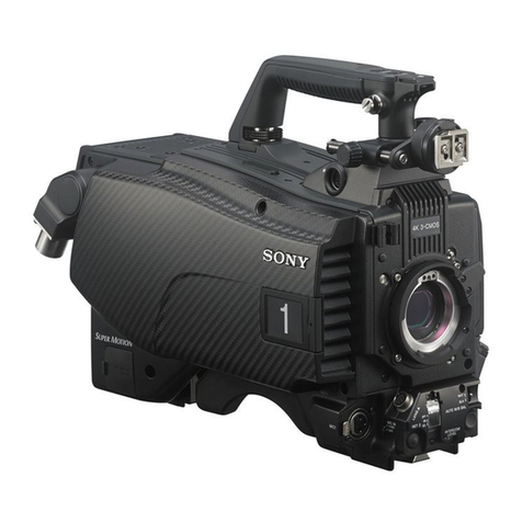
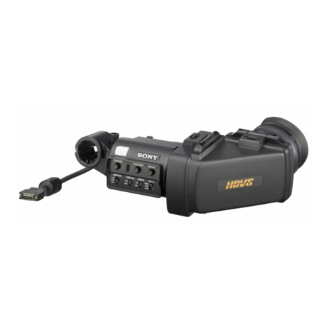
Sony CA-570 User manual

CAMERA ADAPTOR
CA-570
CA-570P
MAINTENANCE MANUAL Part 1
1st Edition (Revised 1)
Serial No. 18001 and Higher: CA-570 (UC)
Serial No. 38001 and Higher: CA-570 (J)
Serial No. 48001 and Higher: CA-570P (CE)

CA-570 P1
!WARNING
This manual is intended for qualified service personnel only.
To reduce the risk of electric shock, fire or injury, do not perform any servicing other than that
contained in the operating instructions unless you are qualified to do so. Refer all servicing to
qualified service personnel.
!WARNUNG
Die Anleitung ist nur für qualifiziertes Fachpersonal bestimmt.
Alle Wartungsarbeiten dürfen nur von qualifiziertem Fachpersonal ausgeführt werden.Um die
Gefahr eines elektrischen Schlages, Feuergefahr und Verletzungen zu vermeiden, sind bei
Wartungsarbeiten strikt die Angaben in der Anleitung zu befolgen.Andere als die angegeben
Wartungsarbeiten dürfen nur von Personen ausgeführt werden, die eine spezielle Befähigung
dazu besitzen.
!AVERTISSEMENT
Ce manual est destiné uniquement aux personnes compétentes en charge de l’entretien. Afin
de réduire les risques de décharge électrique, d’incendie ou de blessure n’effectuer que les
réparations indiquées dans le mode d’emploi à moins d’être qualifié pour en effectuer d’autres.
Pour toute réparation faire appel à une personne compétente uniquement.

1 (E)
CA-570 P1
Table of Contents
Manual Structure
Purpose of this manual ........................................................................................ 2 (E)
Relative manuals ................................................................................................. 2 (E)
Contents ............................................................................................................... 2 (E)
1. Installation
1-1. Checking ROM version.........................................................................1-1 (E)
1-2. Supplied Accessories ............................................................................1-1 (E)
1-3. Connectors and Cables..........................................................................1-1 (E)
1-3-1. Connector Input/Output Signals...........................................1-1 (E)
1-3-2. Connection Connector..........................................................1-6 (E)
1-3-3. Removal of CCZ Connector.................................................1-6 (E)
1-3-4. Wiring Diagrams for Cables ................................................1-7 (E)
1-4. Function of Internal Switches ...............................................................1-9 (E)
1-5. Instance of System Configuration.......................................................1-16 (E)
2. Service Overview
2-1. Removing the Cabinet...........................................................................2-1 (E)
2-2. Location of Printed Wiring Boards .......................................................2-1 (E)
2-3. Notes on Service ...................................................................................2-2 (E)
2-3-1. Circuit Protection Device .....................................................2-2 (E)
2-3-2. Standard Tightening Torque for Screws ..............................2-2 (E)
2-4. Cares After Using at Special Environment ...........................................2-2 (E)
2-5. Self-Diagnosis .......................................................................................2-3 (E)
2-6. Recommended Replacement Parts ........................................................2-6 (E)
2-7. Replacing INCOM 1/2 the Connector...................................................2-7 (E)
2-8. Removing/Installing the DC/DC Converter..........................................2-8 (E)
2-9. Removing/Installing the FL-249 Board ................................................2-9 (E)
2-10. Removing/Installing the AC/DC Converter........................................2-10 (E)

2 (E) CA-570 P1
Manual Structure
Purpose of this manual This manual is the maintenance manual part 1 for Camera Adaptor CA-570/570P.
This manual is intended for use by trained system and service engineers, and
provides the installation and maintenance information that is necessary at the time of
primary service.
Relative manuals Besides this “maintenance manual part 1”, the following manuals are available for
this unit.
..
..
.Operation Manual (Supplied with this unit)
This manual is necessary for application and operation of this unit.
..
..
.Maintenance Manual Part 2 Volume 1, Volume 2
(Available on request)
This manual describes the information items on maintenance, and items that
premise the service based on the components parts such as alignment, schematic
diagrams, board layouts and spare parts list.
If this manual is required, please contact your local Sony Sales Office/Service
Center.
..
..
.System Manual (Available on request)
This manual is necessary for connection and operation of this unit and other
peripheral equipments.
If this manual is required, please contact your local Sony Sales Office/Service
Center.
Contents The following are summaries of all the sections for understanding the contents of
this manual.
Section 1 Installation
Describes information about connector input/output signals, instance of configura-
tion and function of internal switches.
Section 2 Service Overview
Describes information about board locations, recommended replacement part,
replacement of part and notes on services.

1-1 (E)
CA-570 P1
1-1. Checking ROM version
When the CA-570/570P is to be connected to the BVP-
550/550P, be sure to check that the ROM version for IC36/
AT-95 board of the camera is Ver. 4.00 or higher. If ROM
replacement is required, contact your local Sony Sales
Office/Service Center.
In the following cases, it is unnecessary to check.
.When connecting the unit to the BVP-950/950P
.When connecting the unit to the camera which is
provided with the AT-126 board (such as the BVP-550/
550P upgraded by the BKP-5090 or the BVP-570)
ROM Version
IC36/AT-95 board Ver. 4.00 or higher
n
ROM version can be checked easily on the viewfinder
screen. For details, refer to the BVP-550/550P mainte-
nance manual, Section 3 “Setup Menu”.
1-2. Supplied Accessories
Accessory Sony P/N Qt’y
Shoulder Belt A-6772-374-A 1
Cable Holders 3-692-186-01 2
Cable Holder Fixing Screws 7-682-547-09 4
Operation Manual ————— 1
Maintenance Manual Part 1 ————— 1
Section 1
Installation
1-3. Connectors and Cables
1-3-1. Connector Input/Output Signals
.PROMTER *1/GENLOCK *2
BNC 75 Z1.0 V p-p
*1: In connection with CCU
*2: In connection with VTR
.TRIAX
King type (for CA-570)
Fischer type (for CA-570P)
.TEST OUT *3
BNC 75 Z1.0 V p-p
*3: Refer to Section 1-4. “Function of Internal Switches, AU-251 Board”
for details.
REMOTE (8P FEMALE)
(External view)
No. Signal Specifications
1 TX (+) BVP SERIAL DATA
2 TX (_)
3 RX (+) CCU/MSU/RCP/CNU/VCS
4 RX (_) SERIAL DATA
5 VIDEO (G) GND for VIDEO
6 POWER (+) OUT +12 V, 500 mA (MAX)
7 POWER (_) OUT GND for +12 V
8 VIDEO (X) OUT VBS 1.0 V p-p, Zo = 75 Z
CHASSIS GND CHASSIS GND

1-2 (E) CA-570 P1
TRACKER (10P FEMALE)
(External view)
No. Signal Specifications
1 TRACKER R OUT (X) TRACKER RECEIVE
0 dBu unbalanced
2 TRACKER T IN (G) GND for TRACKER T
3 TRACKER R OUT (G) GND for TRACKER R
4 PGM OUT (X) _20 dBu unbalanced
5+12 V (T) OUT +12 V dc. 500 mA (MAX)
6 PGM OUT (G) GND for PGM
7 TRACKER T IN (X) TRACKER TALK
8 TRACKER T IN (Y) 0 dBu/_20 dBu
High impedance balanced
9 UP TALLY OUT (G) GND for UP TALLY
10 UP TALLY OUT (X) +12 V dc 200 mA (MAX)
(0 dBu = 0.775 Vrms)
AUDIO IN 1/2 (3P MALE)
(External view)
No. Signal Specifications
1 MIC IN (G) _60 dBu High impedance
2 MIC IN (X) balanced
3 MIC IN (Y) (0 dBu = 0.775 Vrms)
RET CONT (6P FEMALE)
(External view)
No. Signal Specifications
1 INCOM 1 Zi >10 kZ
MIC ON/OFF IN ON: GND
OFF: OPEN
2 INCOM 2 Zi >10 kZ
MIC ON/OFF IN ON: GND
OFF: OPEN
3 GND
4 RET 3 ON/OFF IN Zi >10 kZ
ON: GND
OFF: OPEN
5 RET 1 ON/OFF IN Zi >10 kZ
ON: GND
OFF: OPEN
6 RET 2 ON/OFF IN Zi >10 kZ
ON: GND
OFF: OPEN
INCOM 1/2 (5P FEMALE)
(External view)
No. Signal Specifications
1 INCOM MIC _20 dBu
IN (Y) (CARBON MIC)
2 INCOM MIC _60 dBu
IN (X) (DYNAMIC MIC)
3 GND (PGM)
4 INCOM _20 dBu
RECEIVE OUT (with INCOM level control
set to mechanical center)
5 PGM 1/2 OUT _20 dBu
(with PGM level control
set to mechanical center)
12
3
4
5
6
78
910
1-3. Connectors and Cables

1-3 (E)
CA-570 P1
VTR (26P MALE)
(External view)
No. Signal Specifications
A POWER (+) IN UNREG 10.5 V to 17 V, 3 A
B POWER (_) IN
1 VBS OUT (X) VBS 1.0 V p-p, Zo = 75 Z
2 VBS OUT (G)
3 Y VIDEO OUT (G) VS 1.0 V p-p, Zo = 75 Z
4 Y VIDEO OUT (X)
5 R-Y VIDEO OUT (X) Zo = 75 Z
6 R-Y VIDEO OUT (G) 756 mV p-p (J)
7 B-Y VIDEO OUT (X) 700 mV p-p (UC)
8 B-Y VIDEO OUT (G) 525 mV p-p (CE)
9 MIC OUT (X) Zo <600 Z,
10 MIC OUT (Y) _60 dBu balanced
11 MIC OUT (G)
12 VTR START/STOP START: 5 ±1 Vdc,
OUT STOP: 0 +0.2 Vdc, Zo <10 kZ
_0.1
13 BATT IND IN Zi = 300 Z*Note 1
14 NC No connection
15 REC ALARM IN Zi >20 kZ*Note 2
16 NC No connection
17 GND (SHIELD) Camera GND
18 PB VIDEO IN (X) VBS 1 V p-p, Zi = 75 Z
19 PB VIDEO IN (G)
20 AUDIO MONITOR IN/ SAVE: +4.5 ±0.5 V,
VTR SAVE OUT
STANDBY: +9.0
+1.0
V, Zo<10 kZ
_0.5
MONITOR: Zi = 750 Z
21 NC No connection
22 CF OUT Color Framing
23 NC No connection
24 NC No connection
(0 dBu = 0.775 Vrms)
n
VTR connector is disabled when the CCU is connected.
DC IN (4P MALE)
(External view)
No. Signal Specifications
1 GND GND for DC (+)
2 NC No connection
3 NC No connection
4 DC (+) IN DC 10.5 V to 17 V
DC OUT (4P FEMALE)
(External view)
No. Signal Specifications
1 GND GND for UNREG
2 NC No connection
3 NC No connection
4 UNREG +12 V OUT +12 V dc, 500 mA (MAX)
1-3. Connectors and Cables

1-4 (E) CA-570 P1
Note1: Specifications of BATT IND Signal
VTR has a battery voltage detection and waring signal generation circuits and it sends the signal shown
below to the camera.
Note2: Specifications of REC ALARM Signal
1-3. Connectors and Cables
Input Signal at
Pin 15
5.0
REC ALARM
signal
1.0 ±0.2 Hz
duty 50 ±10 % REC RESET signal
10—100 ms
VTR Action
Power
OFF Power
ON When VTR changes
from POWER SAVE
to REC START mode,
or when the servo is
lost
When VTR
changes from
STANDBY to
REC START
mode, or in
REC mode
At the end of
tape or When
VTR is put
into STOP
mode by itself
(REC RESET
signal does
not appear
when VTR is
put into STOP
mode by
operating the
camera)
STOP
mode
+1
_0.5 V dc
2.5 ±0.5 V dc
0 ±0.3 V dc
Battery Terminal
Voltage
(VTR internal battery) 17.0—11.1 V dc 11.1—10.8 V dc 10.8 V dc —
2—3 V dc
across 300 Z
0 V
Input Signal at
Pin 13
LED on Viewfinder
1.0 ±0.2 Hz
duty 50 ±10 %
Stays out Blinks at 1 Hz Lights up

1-5 (E)
CA-570 P1
CAMERA (68P MALE)
*: In connection with CCU **: In connection with VTR
No. Signal Specifications
1 UNREG GND GND for UNREG
2 UNREG GND GND for UNREG
3 VF UNREG GND GND for VF UNREG
4 LENS UNREG GND GND for LENS UNREG
5 UNREG OUT 10.5 V to 17 V
6 UNREG OUT 10.5 V to 17 V
7 VF UNREG OUT 10.5 V to 17 V
8 LENS UNREG OUT 10.5 V to 17 V
9 R IN (X)
700 mV p-p ±2 %, DC 0 ±200 mV, Zi >10 kZ
10 B IN (X)
700 mV p-p ±2 %, DC 0 ±200 mV, Zi >10 kZ
11 VBS IN (G) GND for VBS VIDEO
12 Y IN (X) VS 1.0 V p-p, Zi = 1 kZ
13 B-Y IN (X)
700 m V p-p, with sample 350 mV
*
756 mV p-p (J)
700 mV p-p (UC) **
75 % color bars
525 mV p-p (CE)
14 NC No connection
15 NC No connection
16 VBS GENLOCK OUT (X) 1.0 V p-p ±6 dB, Zo = 75 Z
17 RET VIDEO OUT (G) GND for RET VIDEO
18 MONITOR VIDEO IN (X) VS 1 Vp-p, Zi = 1 kZ
19 BATTERY ALARM OUT Zo = 300 Z
20 NC No connection
21 AUDIO CH1 CONT IN 0 V (0 dB) to 7 V (_50 dB or less)
22 MIC 1 IN (Y) Zi >600 Z, _60 dBu balanced
23 NC No connection
24 SKIN TONE GATE IN 1.0 V p-p
25 TAPE REM OUT No connection
26 VTR SYNC IN
+5.0 V p-p Negative pulse, Zi <100 Z
27 RET EN IN ENABLE; 0 V,
DISABLE; +5 V or OPEN
28 PB REF OUT PB; +4.5 V, CAM; 0 V or OPEN
29 H CONT OUT 0 V to 5 V, Analog
30 ANALOG GND
31 DIGITAL HD IN 3.3 V p-p for Digital
32 COM CONT OUT 5 V p-p
33 IIC CLOCK IN (CA) 5 V p-p
34 IIC CLOCK IN (ST) 5 V p-p
No. Signal Specifications
35 UNREG GND GND for UNREG
36 UNREG GND GND for UNREG
37 VF UNREG GND GND for VF UNREG
38 LENS UNREG GND GND for LENS UNREG
39 UNREG OUT 10.5 V to 17 V
40 UNREG OUT 10.5 V to 17 V
41 VF UNREG OUT 10.5 V to 17 V
42 LENS UNREG OUT 10.5 V to 17 V
43 G IN (X)
700 mV p-p ±2 %, DC 0 ±200 mV, Zi >10 kZ
44 R/G/B GND GND for R/G/B VIDEO
45 VBS IN (X) 1.0 V p-p ±10 %, Zi = 75 Z
46 R-Y IN (X) 700 m V p-p, with sync 350 mV *
756 mV p-p (J)
700 mV p-p (UC) **
75 % color bars
525 mV p-p (CE)
47 Y/R-Y/B-Y GND GND for Y/R-Y/B-Y
48 NC No connection
49 NC No connection
50 VBS GENLOCK OUT (G) GND for GENLOCK
51 RET VIDEO OUT (X) 1.0 V p-p, Zo = 75 Z
52 MONITOR VIDEO IN (G) GND for MONITOR VIDEO
53 VTR START/STOP IN Zi <10 kZ
54 NC No connection
55 MIC 1 IN (G) GND for CAM MIC
56 MIC 1 IN (X) Zi >600 Z, _60 dBu balanced
57 NC No connection
58 NC No connection
59 AUDIO LEVEL OUT No connection
60 NC No connection
61 V RESET OUT/CF IN V Reset; 0 V to +5 V,
CF; 0 V to _5 V
62 REC TALLY OUT
ON; +5 V, OFF; +2.5 V or 0 V, Zo>20 kZ
63 VTR SAVE IN
SAVE; +4.5 V, STANDBY; 0 V, Zi <10 kZ
64 GND
65 SD IN/OUT Serial data for camera control
66 COM DATA IN 5 V p-p
67 IIC DATA IN/OUT (CA) 5 V p-p, 4700 Z, Pull up
68 IIC DATA IN/OUT (ST) 5 V p-p, 4700 Z, Pull up
(0 dBu = 0.775 Vrms)
1
35
34
68 (External view)
1-3. Connectors and Cables
1-6 (E) CA-570 P1
1-3-2. Connection Connector
Connection made with the connector panels during instal-
lation or service, should be made with the connectors/
complete cable assemblies specified in the following list,
or equivalent parts.
Connector Name Connection Connectors/Cables
PROMPTER/GENLOCK 1-569-370-12 Plug, BNC
TEST OUT
(BNC)
RET CONT 1-560-078-00 Plug, 6P Male or
(6P FEMALE) HIROSE HR10-7PA-6P equivalent
REMOTE 1-766-848-11 Plug, 8P Male or
(8P FEMALE) CCA-5 cable assembly (option)*2
CCA-5-10 (10 m)/CCA-5-3 (3 m)or
REMOTE cable 1-783-372-11
(supplied with RM-B150, 10 m) *1 *2
INCOM 1/2 1-508-370-11 XLR, 5P Male or
(5P FEMALE) CANNON XLR-5-12C equivalent
AUDIO IN 1/2 1-508-084-00 XLR, 3P Female or
(3P MALE) CANNON XLR-3-11C equivalent
DC IN 1-508-362-00 XLR, 4P Female or
(4P MALE) CANNON XLR-4-11C equivalent or
Cable assembly (supplied with AC-550)
1-551-577-00
DC OUT 1-566-425-11 Plug, 4P Male or
(4P FEMALE) HIROSE HR10A-7P-4P equivalent
VTR 1-564-184-00 Plug, 26P Female or
(26P MALE) CCZ cable assembly (option) or
CCZ-2 (2 m)/CCZ-10 (10 m)
TRACKER 1-506-522-11 Plug, 10P Male or
(10P FEMALE) HIROSE HR10R-10P-10P equivalent
*1: Use of REMOTE cable enables to monitor video signals.
*2: If using a cable of length different from a standard product, consult your
Sony organization.
1-3-3. Removal of CCZ Connector
1. Remove the two screws and three setscrews.
2. Connect the plug to the VTR or camera.
3. Loosen the plug counterclockwise by pliers.
4. Disassemble as illustrated and unsolder.
1-3. Connectors and Cables

1-7 (E)
CA-570 P1
26P CONNECTOR (FEMALE/MALE)
(WIRING SIDE)
1-3-4. Wiring Diagrams for Cables
CCZ Cable
1-3. Connectors and Cables

1-8 (E) CA-570 P1
CCA-5 Cable
(Outer sheath color : White)
REMOTE Cable (supplied with RM-B150)
(Outer sheath color : Black)
Black
Red
Brown
White
White
White
8P CONNECTOR(MALE)
(WIRING SIDE) 8P CONNECTOR(MALE)
(WIRING SIDE)
1
287
63
5
4
1
287
63
5
4
1
287
63
5
4
1
287
63
5
4
Black
Red
Red
Brown
BrownBrown
White
White
White
Orange
8P CONNECTOR(MALE)
(WIRING SIDE) 8P CONNECTOR(MALE)
(WIRING SIDE)
1-3. Connectors and Cables

1-9 (E)
CA-570 P1
S1
1234
E
D
C
B
A
MB-783 BOARD (B SIDE)
1-4. Function of Internal Switches
MB-783 board
Ref.No. Name Description Factory setting
S1-1 PGM Turns on and off the function to monitor the PGM (program audio) by the earphone ON
ON: Monitoring is enabled
OFF: Monitoring is disabled
S1-2 INCOM 2 Turns on and off the function to monitor the NCOM 2 intercom audio by the earphone OFF
ON: Monitoring is enabled
OFF: Monitoring is disabled
S1-3 INCOM 1 Turns on and off the function to monitor the INCOM 1 intercom audio by the earphone OFF
ON: Monitoring is enabled
OFF: Monitoring is disabled
S1-4 VTR Turns on and off the function to monitor the VTR playback audio by the earphone OFF
while the VTR is playing back
ON: Monitoring is enabled
OFF: Monitoring is disabled
1-4. Function of Internal Switches

1-10 (E) CA-570 P1
S1
S4
A
B
C
D
E
F
G
1234
DM-116 BOARD (A SIDE)
DM-116 board
Ref.No. Name Description Factory setting
S1 PROMPT/GEN Factory use PROMPT
n
Do not change this switch from its factory setting
S4 CCU8CAM Selects the direction to transmit the PROMPTER signal as follows. CCU8CAM
/CAM8CCU (This switch is activated only when the unit is connected with the CCU-700A/700AP)
CCU8CAM: PROMPTER signal is transmitted from the CCU to the unit and
is then output at the PROMPTER/GENLOCK connector of the unit
CAM8CCU: PROMPTER signal is input at the PROMPTER/GENLOCK connector
of the unit and is then transmitted to the CCU
n
When this switch is changed to “CAM8CCU”side, be sure to disconnect
the RF cable (green) and connect it to a proper connector on the DM-116 board
as shown in the figure above
In addition, be sure to change the setting of S5 and S6 switches on the DM board
of the CCU from TX to RX
1-4. Function of Internal Switches
RF cable connection
RF cable (Green)
MD-116

1-11 (E)
CA-570 P1
S3
CN1
4 3 21
A
B
C
D
E
F
MD-119 BOARD (A SIDE)
MD-119 board
Ref.No. Name Description Factory setting
S3 PROMPTER/ Selects input or output signal at the PROMPTER/GENLOCK connector (BNC) PROMPTER
GENLOCK PROMPTER: Select to input or to output a PROMPTER signal when the CCU is
(Panel) connected to the unit
S4/DM-116 board selects whether the PROMPTER signal is
input (CCU8CAM) or is output (CAM8CCU)
GENLOCK: Select to input a VBS or a GENLOCK signal
n
Check that the S1/DM-116 board is set to PROMPT side
1-4. Function of Internal Switches

1-12 (E) CA-570 P1
Ref.No. Name Description Factory setting
S1 MIX/IND Not used (Always set to OFF) OFF
S2 *, S4 * INCOM1 PGM MIX Selects how the INCOM and PGM of the INCOM 1 connector are output (See the table below)
S3 *, S5 * INCOM2 PGM MIX Selects how the INCOM and PGM of the INCOM 2 connector are output (See the table below)
*: AU-237 board only. (The AU-237P board is not equipped with these switches.)
INCOM/PGM MIX mode select switches (AU-237 board only)
INCOM1 S2 S4 Description
INCOM2 S3 S5
IND IND INCOM and PGM are output independently
(Factory setting)
MIX IND Mixed signal of INCOM and PGM is output as
INCOM and PGM outputs
INCOM level control knob adjusts INCOM audio
level and PGM level control knob adjusts the
PGM audio level
MIX MIX Mixed signal of INCOM and PGM is output as
INCOM and PGM outputs
INCOM level control knob adjusts mixed signal
level of the INCOM and PGM, and PGM level
control knob adjusts the balance between them
AU-237/237P board
CA-570 (UC) : S/N 18001 and Higher CA-570 (UC) : S/N 10001 through 18000
CA-570 P (CE) : S/N 48001 and Higher CA-570 P (CE) : S/N 40001 through 48000
F
E
D
C
B
A
1234
CN1
S2 *
S3 *
S4 *
S5 *
S111
S181
S182
S183
S301
S302
S362
S363
S411
AU-237 BOARD (A SIDE)
INCOM
PGM
INCOM
OUT
PGM
OUT
1-4. Function of Internal Switches
INCOM
PGM
INCOM
OUT
PGM
OUT
INCOM
PGM
INCOM
OUT
PGM
OUT
F
E
D
C
B
A
1234
CN1
S1 S2*
S3*
S4*
S5*
S111
S181
S182
S183
S301
S302
S362
S363
S411
AU-237 BOARD (A SIDE)

1-13 (E)
CA-570 P1
1-4. Function of Internal Switches
Ref.No. Name Description Factory setting
S111 RTS1 Select when connecting an RTS kit to the INCOM 1 connector. NORM
RTS: RTS CH1 is activated as INCOM 1 connector
NORM: Normal mode
S302 RTS2 Select when connecting an RTS kit to the INCOM 2 connector. NORM
RTS: RTS CH2 is activated as INCOM 2 connector
NORM: Normal mode
S181-1 UNBAL/BAL Turns on and off the function to ground the MIC (Y) signal when a headset UNBAL
with dynamic microphone is connected to the INCOM 1 connector and
the connection is unbalanced
BAL: Normal mode
UNBAL: MIC(Y) signal is grounded (This reduces hum)
S181-2 UNBAL/BAL Turns on and off the function to ground the MIC (Y) signal when a headset UNBAL
with dynamic microphone is connected to the INCOM 2 connector and
the connection is unbalanced
BAL: Normal mode
UNBAL: MIC(Y) signal is grounded (This reduces hum)
S182 INTERCAM1 Select according to a microphone of the headset to be connected to CB (Carbon)
CB/DYN INCOM 1 connector
(Panel) CB: Carbon microphone
DYN: Dyanmic microphone
S362 INTERCAM2 Select according to a microphone of the headset to be connected to CB (Carbon)
CB/DYN INCOM 2 connector
(Panel) CB: Carbon microphone
DYN: Dyanmic microphone
S183 GAIN Sets the level of INCOM 1 intercom audio to be sent to the CCU 0 (0 dB)
(Panel) +: The gain is increased by about 6 dB againt standard level
0: Standard level
_: The gain is decreased by about 6 dB againt standard level
S363 GAIN Sets the level of INCOM 2 intercom audio to be sent to the CCU 0 (0 dB)
(Panel) +: The gain is increased by about 6 dB againt standard level
0: Standard level
_: The gain is decreased by about 6 dB againt standard level
S301 TRACKER/INCOM2 mode select switches
S301-1 TRACKER/PGM Turns on and off the function to add PGM (program audio) to
(PGM/R) the TRACKER RECEIVE OUT ON
ON: The PGM is added to the TRACKER RECEIVE OUT
OFF: Normal mode
S301-2 TRACKER/INCOM2 Turns on and off the function to add the INCOM 2 audio (TALK/RECEIVE) OFF
to the TRACKER RECEIVE OUT
(IN2R/R) ON: The INCOM 2 audio is added to the TRACKER RECEIVE OUT
OFF: Normal mode
S301-3 TRACKER/INCOM2 Turns on and off the function to add the TRACKER TALK to the INCOM 2 OFF
(T/IN2R) audio (TALK) to be sent to the CCU
ON: The TRACKER TALK is added to the INCOM 2 audio (TALK)
OFF: Normal mode
S301-4 TRACKER/INCOM2 Turns on and off the function to add the TRACKER TALK to the INCOM 2 OFF
(T/IN2R) audio (RECEIVE) sent from the CCU
ON: The TRACKER TALK is added to the INCOM 2 audio (RECEIVE)
OFF: Normal mode
S411 TRACKER Selects the TRACKER TALK level at the TRACKER connector 0 (0 dBu)
(T) 0/_20 0: 0 dBu (Standard level)
_20: _20 dBu (Select when input level is too high)
(0 dBu = 0.775 Vrms)

1-14 (E) CA-570 P1
CN1
S600
S700
S800
S100
S200
S351
4 3 21
A
B
C
D
E
F
AU-251 BOARD (A SIDE)
AU-251 board
Ref.No. Name Description Factory setting
S600 MIC1 Selects a MIC signal which is sent to the CCU as MIC 1 input CA
CHU/CA CHU: Camera MIC connector input
CA: Camera adaptor MIC 1 connector input
S700 MIC +48 V MIC POWER +48 V ON/OFF switch OFF
Turn on when using a PHANTOM +48 V microphone
S800 MIC +12 V MIC POWER +12 V ON/OFF switch OFF
Turn on when using an AB POWERING +12 V microphone
n
When the MIC POWER switch on the rear panel to OFF or +48 V,
this switch is not activated even if set to ON
S200-1 RCP POWER Turns on and off the power saving function for RCP drive circuit when the CCU ON
SAVE is connected to the unit
ON: Power for the RCP drive circuit is turned off when the CCU is connected
(Turned on when the camera is used alone)
OFF: Always turned on
S200-2 BATTERY Turns on and off the function to light the back tally lamp of the unit when the battery OFF
ALARM signal circuit is detected
ON: Back tally lamp is lit
OFF: Back tally lamp is unlit
S351 MIC Turn on and off the function to monitor the MIC input by the headset connected to OFF
MONITOR the INCOM connector
ON: Monitoring is enabled
OFF: Monitoring is disabled
1-4. Function of Internal Switches

1-15 (E)
CA-570 P1
Ref.No. Name Description Factory setting
S100 TEST OUT signal select switch
n
The table below shows selectable output signals in combination with S100-1 through S100-4
and depending on whether the RET CONT signal is low or high
S100-1 PB VIDEO/RET Disables automatically switching between PB VIDEO and RET VIDEO OFF
signals when S100-1 is set to ON
S100-2 VBS/RET Disables automatically switching between VBS/MONITOR and OFF
PB/RET VIDEO signals when S100-2 is set to ON
S100-3 MONITOR/VBS Selects MONITOR or VBS signal OFF
S100-4 RET CONT Inhibits the RET CONT signal when S100-4 is set to OFF ON
Selecting TEST OUT signal
S100-1 S100-2 S100-3 S100-4 RET CONT Output signal at TEST OUT connector
OFF OFF X X X RET VIDEO OUT (in connection with CCU)
PB VIDEO OUT (in connection with VTR)
ON OFF X X X PB VIDEO OUT
X ON OFF OFF X VBS OUT
X ON ON OFF X MONITOR OUT
OFF ON OFF ON Low RET VIDEO OUT (in connection with CCU)
Low PB VIDEO OUT (in connection with VTR)
High VBS OUT
OFF ON ON ON Low RET VIDEO OUT (in connection with CCU)
Low PB VIDEO OUT (in connection with VTR)
High MONITOR OUT
X: Don’t care.
1-4. Function of Internal Switches

1-16 (E) CA-570 P1
ENG/EFP LENS
2" VF(BVF-20W/20WCE)
1.35" COLOR VF(BVF-C10W)
1.5" VF(BVF-10/10CE)
2" VF(BVF-20W/20WCE)
1.35" COLOR VF(BVF-C10W)
1.5" VF(BVF-10/10CE)
COLOR VIDEO CAMERA
BVP-950/950P
ELECTRONIC
VIEWFINDER
BVF-55/55CE
CAMERA ADAPTOR
CA-570/570P
CA-550/550P
CCD UNIT
OHB-750A/750AP
OHB-730/730P
STUDIO ZOOM LENS
TRIAX CABLE (*1)
TRIAX CABLE (*1)
COLOR VIDEO CAMERA
BVP-900/900P
4 : 3
16 : 9
OHB-750WSA/750WSAP
OHB-730WS/730WSP
BVF-7700/7700P
ELECTRONIC VIEWFINDER
BVF-77/77CE
4 : 3
16 : 9
4 : 3
16 : 9
OHB-750WSA/750WSAP
OHB-730WS/730WSP
CCD UNIT
OHB-750A/750AP
OHB-730/730P
CCD UNIT
OHB-450/450P
OHB-451/451P
OHB-550/550P
ENG/EFP LENS
OHB-455WS/455WSP
OHB-550WS/550WSP
OHB-T450WS/T450WSP
COLOR VIDEO CAMERA
BVP-550
BVP-570
*1: TRIAX Cable length
Diameter Maximum length
CCU-700 CCU-550
8.5 mm 1000 m 700 m
14.5 mm 2000 m 1400 m
Diameter Cable-lenght limitation for prompter signal transmission
CCU →CAM CAM →CCU
8.5 mm 500 m 400 m
14.5 mm 1000 m 800 m
1-5. Instance of System Configuration
Other manuals for CA-570
1
This manual suits for next models
1
Table of contents
Other Sony Camera Accessories manuals

Sony
Sony CBK-3610XS User manual

Sony
Sony XCD-SX910CR User manual

Sony
Sony MPK-THD User manual

Sony
Sony VCT-870RM User manual

Sony
Sony SRMASTER SR-PC4 User manual

Sony
Sony HVR-Z1J User manual

Sony
Sony SRK-R302 User manual

Sony
Sony G MASTER FE 14mm F1.8 GM User manual

Sony
Sony VG-C4EM User manual

Sony
Sony VG-C70AM Operating Instructions / Manual de instrucciones / Mode... User manual