Tripod
Trépied
3-076-954-12(1)
Operating Instructions
Mode d‘emploi
Bedienungsanleitung
Manual de instrucciones
Gebruiksaanwijzing
Bruksanvisning
Инструкция по пользованию
Istruzioni per l’uso
Manual de instruções
使用說明書
사용설명서
VCT-R640
Sony Corporation ©2002 Printed in China
English
Features
The VCT-R640 is a tripod for
video camera recorders/digital
still cameras.
Caution
Never carry the tripod with the
video camera recorder/digital
still camera attached.
Cleaning
•Clean the tripod with a soft
cloth lightly moistened with a
mild detergent solution.
•After using the tripod at a
location subject to sea breezes,
be sure to wipe it clean with a
dry cloth.
Specifications
Maximum load
3 kg (6 lb 10 oz)
Panning angle
360 degrees
Tilting angle
90 degrees down,
65 degrees up
Stages of legs
3 stages
Dimensions
Maximum height:
Approx. 1 441 mm
(563⁄4inches)
(Legs spread and elevator
used)
Minimum height:
Approx. 548 mm (215⁄8inches)
Pan handle length:
Approx. 275 mm (107⁄8inches)
Elevator stroke:
Approx. 296 mm (113⁄4inches)
Mass
Approx. 1.2 kg (2 lb 10 oz)
Supplied accessory
Operating instructions (1)
Design and specifications are
subject to change without notice.
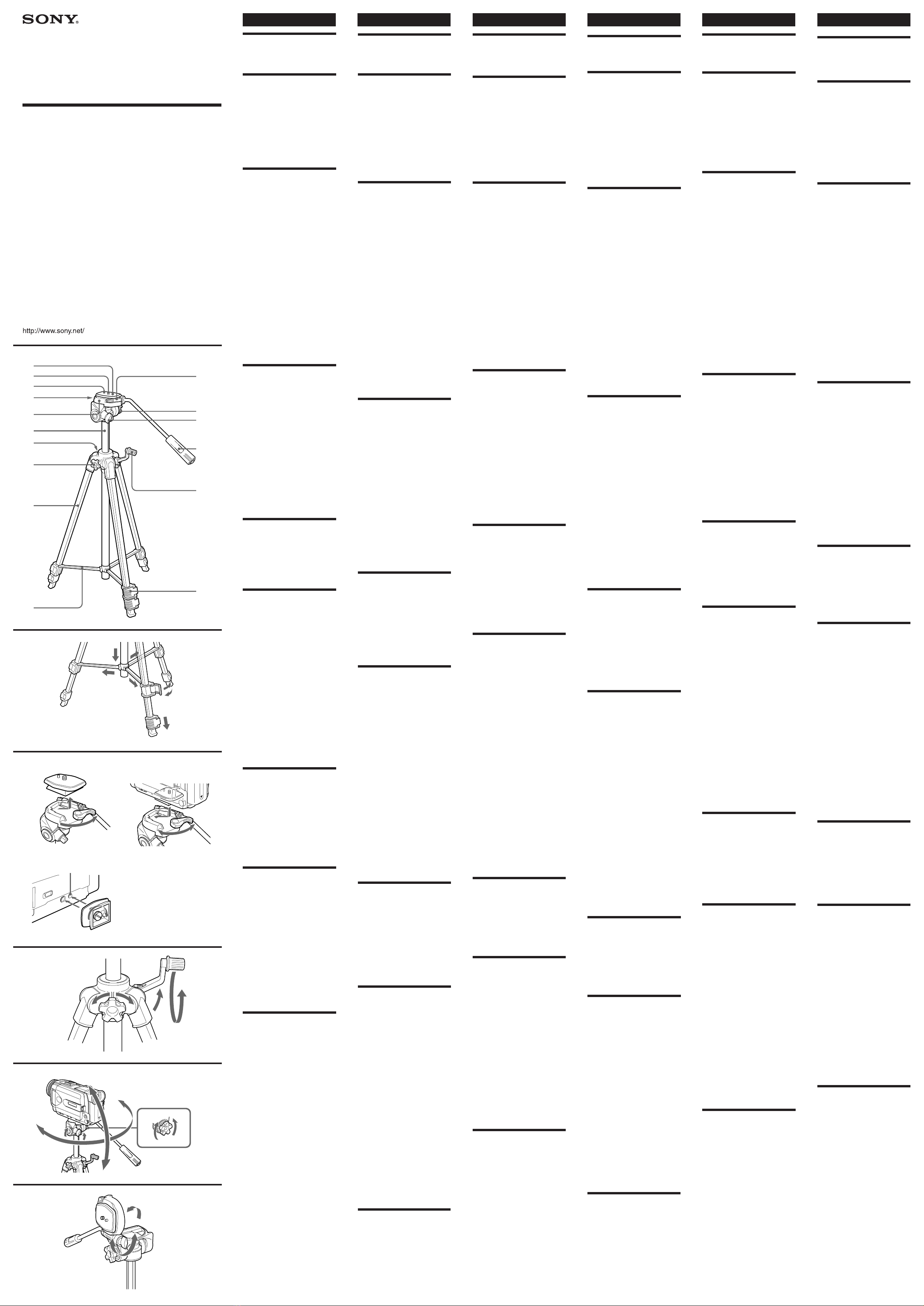
AIdentifying the
Parts
1Camera mounting shoe
2Camera mounting screw and
knob
3Pin
4Tripod head lock knob
5Tripod head
6Elevator
7Level
8Elevator lock knob
9Leg
10 Stay
11 Camera mounting shoe lock
lever
12 Pan lock knob
13 Tilt lock knob
14 Pan handle
15 Elevator length adjustment
crank
16 Leg length adjustment lock
lever
BSetting the Tripod
1Spread the legs until the
tripod becomes stable.
2Press down the stay.
3Unlock the leg length
adjustment lock levers.
4Adjust the length of the legs.
5Lock the leg length
adjustment lock levers.
CMounting the
Camera
Install the battery pack, “Memory
Stick” and a cassette in the video
camera recorder/digital still camera
before mounting to the tripod.
1While pulling the camera
mounting shoe lock lever
fully to the right, slide out the
camera mounting shoe from
the tripod head.
2Attach the camera mounting
shoe to the camera. Tighten
the screw firmly.
When you attach the video
camera recorder, aline the pin
with the positioning hole (a).
3While pulling the camera
mounting shoe lock lever
fully to the right, replace the
camera mounting shoe with
the camera attached into the
tripod head. Then, push the
camera mounting shoe lock
lever to the left to lock.
DAdjusting the
Height of the
Elevator
1Loosen the elevator lock
knob.
2Open the elevator length
adjustment crank.
3Adjust the height by rotating
the elevator length
adjustment crank.
4Tighten the elevator lock
knob.
EPanning and
Tilting
Before panning and tilting, make
sure that the elevator lock knob is
locked firmly. If it is unlocked, it
will cause a camera shake.
Panning
1Loosen the pan lock knob.
2Adjust the position of the
camera by moving the pan
handle.
3Tighten the pan lock knob.
Tilting
4Loosen the tilt lock knob.
5Adjust the position of the
camera by moving the pan
handle.
6Tighten the tilt lock knob.
FChanging the
Angle of the
Tripod head
The horizontal shooting position
of the camera can be changed to
the vertical shooting position.
•Loosen the tripod head lock
knob, stand the tripod head to
the right, then tighten the tripod
head lock knob.
Español
Características
El VCT-R640 es un trípode para
videocámaras/cámaras digitales.
Precaución
No lleve el trípode con la
videocámara/cámara digital
instalada.
Limpieza
•Limpie el trípode con un paño
suave ligeramente humedecido
en una solución de detergente
suave.
•Después de haber utilizado el
trípode en un lugar sometido a
la brisa del mar, cerciórese de
limpiarlo frotándolo con un
paño seco.
Especificaciones
Carga máxima
3 kg
Ángulo de panorámica
360 grados
Ángulo de picado
90 grados hacia abajo,
65 grados hacia arriba
Alturas de las patas
3 alturas
Dimensiones
Altura máxima:
Aprox. 1 441 mm
(Patas desplegadas y
elevador utilizado)
Altura mínima:
Aprox. 548 mm
Longitud del mango de
panorámica: Aprox. 275 mm
Carrera del elevador:
Aprox. 296 mm
Masa
Aprox. 1,2 kg
Accesorio suministrado
Manual de instrucciones (1)
El diseño y las especificaciones
están sujetos a cambio sin previo
aviso.
AIdentificación de
partes
1Zapata para montaje de la
cámara
2Tornillo y perilla de montaje
de la cámara
3Pasador
4Perilla de bloqueo de la
cabeza del trípode
5Cabeza del trípode
6Elevador
7Nivel
8Perilla de bloqueo del
elevador
9Pata
10 Tirante
11 Palanca de bloqueo de la
zapata para montaje de la
cámara
12 Perilla de bloqueo de
panorámica
13 Seguro de inclinación
14 Mango de panorámica
15 Manivela elevadora
16 Palanca de bloqueo del ajuste
de longitud de las patas
BAjuste del trípode
1Separe las patas hasta que el
trípode quede estable.
2Presione hacia abajo el
tirante.
3Desbloquee las palancas de
bloqueo del ajuste de
longitud de las patas.
4Ajuste la longitud de las
patas.
5Bloquee las palancas de
bloqueo del ajuste de
longitud de las patas.
CMontaje de la
cámara
Instale la batería, un “Memory
Stick”, y un videocasete en la
videocámara/cámara digital
antes de montarla en el trípode.
1Tirando de la palanca de
bloqueo de la zapata para
montaje de la cámara
completamente hacia la
derecha, deslice dicha zapata
hacia fuera de la cabeza del
trípode.
2Fije la zapata para montaje de
la cámara a ésta. Apriete
firmemente el tornillo.
Cuando fije la videocámara,
alinee el pasador con el
orificio de ubicación (a).
3Tirando de la palanca de
bloqueo de la zapata para
montaje de la cámara
completamente hacia la
derecha, devuelva dicha
zapata con la cámara
montada a la cabeza del
trípode. Después, empuje la
palanca de bloqueo de la
zapata para montaje de la
cámara hacia la izquierda
para bloquear.
DAjuste de la altura
del elevador
1Afloje la perilla de bloqueo
del elevador.
2Abra la manivela elevadora.
3Ajuste la altura girando la
manivela elevadora.
4Apriete la perilla de bloqueo
del elevador.
EPanorámica y
picado
Antes de utilizar las funciones de
panorámica y picado, cerciórese
de que el elevador esté
firmemente bloqueado con la
perilla de bloqueo del mismo. Si
quedase desbloqueado, la cámara
podría sufrir sacudidas.
Panorámica
1Afloje la perilla de bloqueo
de panorámica.
2Ajuste la posición de la
cámara moviendo el mango
de panorámica.
3Apriete la perilla de bloqueo
de panorámica.
Picado
4Afloje el seguro de
inclinación.
5Ajuste la posición de la
cámara moviendo el mango
de panorámica.
6Apriete el seguro de
inclinación.
Français
Caractéristiques
Le VCT-R640 est un trépied pour
caméscopes/appareils photo
numériques.
ATTENTION
Ne jamais transporter le trépied
par le caméscope numérique ou
l’appareil photo.
Nettoyage
•Nettoyez le trépied avec un
chiffon doux, légèrement
imprégné d’une solution
détergente douce.
•Si vous avez utilisé le trépied à
un endroit exposé aux embruns
marins, essuyez-le bien avec un
chiffon sec avant de le ranger.
Spécifications
Charge maximale
3 kg (6 li 10 on)
Angle de panoramique
horizontal
360 degrés
Angle de panoramique vertical
90 degrés vers le bas
65 degrés vers le haut
Niveaux des pieds
3 niveaux
Dimensions
Hauteur maximale :
Appro. 1 441 mm (563⁄4pouces)
(avec pieds écartés et élévateur)
Hauteur minimale :
Approx. 548 mm (215⁄8pouces)
Longueur de la poignée
panoramique :
Approx. 275 mm (107⁄8pouces)
Tige d’élévateur :
Approx. 296 mm (113⁄4
pouces)
Poids
Approx. 1,2 kg (2 li 10 on)
Accessoire fourni
Mode d’emploi (1)
La conception et les spécifications
peuvent être modifiées sans avis
préalable.
ANomenclature
1Sabot de montage
2Vis et molette de montage
3Broche
4Molette de verrouillage de la
tête de trépied
5Tête de trépied
6Elévateur
7Niveau à bulle
8Molette de verrouillage
d’élévateur
9Pied
10 Montant
11 Levier de verrouillage de
sabot de montage
12 Molette de verrouillage de
panoramique
13 Bouton de verrouillage de
panoramique vertical
14 Poignée de panoramique
15 Manivelle de réglage en
hauteur de l’élévateur
16 Levier de verrouillage de
réglage de la longueur du pied
BRéglage du trépied
1Ecartez les pieds jusqu’à ce
que le trépied soit stable.
2Baissez le montant.
3Débloquez les leviers de
verrouillage du réglage de la
longueur des pieds.
4Ajustez la longueur des
pieds.
5Rebloquez les leviers de
verrouillage du réglage de la
longueur des pieds.
CMontage du
caméscope/
appareil photo
Installez la batterie, un “Memory
Stick” et une cassette dans
l’appareil photo/caméscope
numérique avant de le mettre sur
le trépied.
1Tout en tirant le levier de
verrouillage du sabot de
montage complètement vers
la droite, détachez le sabot de
montage de la tête de trépied.
2Fixez le sabot de montage au
caméscope/appareil photo.
Serrez bien la vis.
Lorsque vous fixez un
caméscope, alignez la broche
sur l’orifice de
positionnement (a).
3Tout en tirant le levier de
verrouillage du sabot de
montage vers la droite,
remettez le sabot de montage
avec le caméscope/appareil
photo dans la tête de trépied.
Poussez ensuite le levier de
verrouillage du sabot de
montage vers la gauche pour
bloquer le sabot.
DRéglage de la
hauteur de
l’élévateur
1Desserrez la molette de
verrouillage de l’élévateur.
2Dépliez la manivelle de
réglage en hauteur de
l’élévateur.
3Réglez la hauteur du trépied
en agissant sur la manivelle
de réglage de l’élévateur.
4Serrez la molette de
verrouillage de l’élévateur.
EPanoramiques
horizontal et
vertical
Avant de faire un panoramique
horizontal ou vertical, assurez-
vous que la molette de
verrouillage de l’élévateur est
bien verrouillée. Si elle ne l’est
pas, appareil photo le caméscope
risque de bouger.
Panoramique horizontal
1Desserrez la molette de
verrouillage de panoramique.
2Réglez la position du
caméscope/appareil photo en
bougeant la poignée de
panoramique.
3Serrez la molette de
panoramique.
Panoramique vertical
4Desserrez le bouton de
verrouillage de panoramique
vertical.
5Ajustez la position du
caméscope/appareil photo en
bougeant la poignée de
panoramique.
6Serrez le bouton de
verrouillage de panoramique
vertical.
Deutsch
Merkmale
Das Stativ VCT-R640 ist für
digitale Standbildkameras und
Camcorder bestimmt.
Vorsicht
Tragen Sie das Stativ nicht mit
angebrachter Standbildkamera
bzw. angebrachtem Camcorder.
Reinigung
•Verwenden Sie zur Reinigung
des Stativs ein weiches, leicht
mit einer milden
Reinigungslösung
angefeuchtetes Tuch.
•Nach dem Einsatz des Stativs in
Meeresluft wischen Sie es mit
einem weichen Tuch ab.
Technische Daten
Maximale Tragfähigkeit
3 kg
Schwenkwinkel
360 Grad
Neigewinkel
90 Grad nach unten,
65 Grad nach oben
Beinelemente
3 Stufen
Abmessungen
Max. Höhe: ca. 1 441 mm
(bei Beinspreizung und
Liftbetrieb)
Minimale Höhe: ca. 548 mm
Länge des Schwenkarms:
ca. 275 mm
Höhenverstellung:
ca. 296 mm
Gewicht
ca. 1,2 kg
Mitgeliefertes Zubehör
Bedienungsanleitung (1)
Änderungen, die dem
technischen Fortschritt dienen,
bleiben vorbehalten.
ABezeichnung der
Teile
1Kameramonatageschuh
2Kamerabefestigungsschraube
und -knopf
3Zapfen
4Stativkopfverriegelungsknopf
5Stativkopf
6Lift
7Libelle
8Liftverriegelungsknopf
9Bein
10 Strebe
11 Verriegelungshebel des
Kameramontageschuhs
12 Schwenkverriegelungsknopf
13 Neigeverriegelungsknopf
14 Schwenkarm
15 Liftkurbel
16 Verriegelung für
Beinlängeneinstellung
BAufstellen des
Stativs
1Spreizen Sie die Stativbeine,
damit das Stativ stabil steht.
2Drücken Sie die Strebe nach
unten.
3Lösen Sie die Verriegelung
für die
Beinlängeneinstellung.
4Stellen Sie die Länge der
Beine ein.
5Verriegeln Sie die
Verriegelung für die
Beinlängeneinstellung.
CAnbringen der
Kamera
Setzen Sie den Akku, den „Memory
Stick“ und die Cassette in die
digitale Standbildkamera bzw. den
Camcorder ein, bevor Sie die
Kamera wie folgt auf dem Stativ
montieren.
1Halten Sie den
Verriegelungshebel des
Kameramontageschuhs ganz
nach rechts gedrückt, und
schieben Sie gleichzeitig den
Kameramontageschuh aus dem
Stativkopf heraus.
2Bringen Sie den
Kameramontageschuh an der
Kamera an, und ziehen Sie die
Schraube gut fest.
Im Falle eines Camcorders
muss darauf geachtet werden,
dass der Zapfen in die Bohrung
eingreift (a).
3Halten Sie den
Verriegelungshebel des
Kameraschuhs ganz nach
rechts gedrückt, und schieben
Sie gleichzeitig den
Kameramontageschuh mit der
daran befestigten Kamera in
den Stativkopf. Drücken Sie
dann den Verriegelungshebel
des Kameramonatageschuhs
nach links, um ihn zu
verriegeln.
DHöhenverstellung
1Lösen Sie den
Liftverriegelungsknopf.
2Klappen Sie die Liftkurbel
heraus.
3Stellen Sie die Höhe mit der
Liftkurbel ein.
4Ziehen Sie den
Liftverriegelungsknopf
wieder fest.
ESchwenken und
Neigen
Der Liftverriegelungsknopf muss
fest zugedreht werden, bevor Sie
die Kamera schwenken oder
neigen. Ansonsten wackelt die
Kamera möglicherweise.
Schwenken
1Lösen Sie den
Schwenkverriegelungsknopf.
2Stellen Sie die Position der
Kamera mit dem
Schwenkarm ein.
3Arretieren Sie die
Schwenkverriegelung.
Neigen
4Lösen Sie den
Neigeverriegelungsknopf.
5Stellen Sie die Position der
Kamera mit dem
Schwenkarm ein.
6Arretieren Sie den
Neigeverriegelungsknopf.
FÄndern des
Stativkopfwinkels
Das Stativ eignet sich sowohl für
Horizontal- als auch für
Vertikalaufnahmen.
•Lösen Sie den
Stativkopfverriegelungsknopf,
kippen Sie den Stativkopf
senkrecht nach rechts, und
arretieren Sie den Knopf
wieder.
Nederlands
Kenmerken
De VCT-R640 is een statief voor
een videocamera-recorder/
digitale fotocamera.
Voorzichtig
Draag nooit het statief mee
zolang er een videocamera-
recorder/digitale fotocamera op
is bevestigd.
Reinigen
•Veeg het statief schoon met een
zachte doek, licht bevochtigd
met wat milde vloeibare zeep.
•Als u het statief gebruikt aan de
kust, met zilte zeewind, veeg
het daarna dan zorgvuldig
schoon met een droge doek.
Technische gegevens
Maximaal draagvermogen
3 kg
Horizontale draaihoek
360 graden
Verticale kantelhoek
90 graden omlaag,
65 graden omhoog
Pootsegmenten
3 segmenten
Afmetingen
Maximale hoogte: ca. 1 441
mm
(poten geheel gespreid en
verlenghals uitgeschoven)
Minimale hoogte: ca. 548 mm
Lengte zwenkhandgreep:
ca. 275 mm
Instelbereik verlenghals:
ca. 296 mm
Gewicht
ca. 1,2 kg
Bijgeleverd toebehoren
Gebruiksaanwijzing (1)
Wijzigingen in ontwerp en
technische gegevens
voorbehouden, zonder
kennisgeving.
APlaats en functie
van de onderdelen
1Camera-montageschoen
2Camera-montageschroef en
borgring
3Camera-borgpen
4Borgknop voor statiefkop
5Statiefkop
6Verlenghals
7Waterpas
8Hoogtevergrendelknop
9Poot
10 Steun
11 Borgknop voor camera-
montageschoen
12 Zwenkvergrendelknop
13 Kantelborgknop
14 Zwenkhandgreep
15 Middenzuil-hoogtezwengel
16 Pootlengte-vergrendelknop
B
Het statief opstellen
1Spreid de poten totdat het
statief stevig blijft staan.
2Druk de steun omlaag.
3Zet de pootlengte-
vergrendelknoppen los.
4Schuif de poten uit tot de
gewenste lengte.
5Zet de pootlengte-
vergrendelknoppen weer
vast.
C
De camera aanbrengen
Installeer een batterijpak, een
“Memory Stick” en een
videocassette in de videocamera-
recorder/digitale fotocamera
alvorens u die op het statief
aanbrengt.
1Trek de borgknop voor de
camera-montageschoen geheel
naar rechts en schuif de
camera-montageschoen van de
statiefkop af.
2Bevestig de camera-
montageschoen onder aan de
camera. Draai de borgschroef
stevig vast.
Bij het aanbrengen van een
videocamera-recorder zorgt u
dat de camera-borgpen in de
daarvoor bestemde opening (a)
valt.
3Trek de borgknop voor de
camera-montageschoen weer
helemaal naar rechts en schuif
de camera-montageschoen met
de camera op de statiefkop.
Druk dan de borgknop voor de
camera-montageschoen naar
links om de camera vast te
zetten.
DHoogte instellen
met de verlenghals
1Draai de
hoogtevergrendelknop los.
2Klap de middenzuil-
hoogtezwengel uit.
3Stel de hoogte in door aan de
middenzuil-hoogtezwengel
te draaien.
4Draai de
hoogtevergrendelknop weer
vast.
EZijwaarts draaien en
voor/achterwaarts
kantelen
Alvorens u de camera zijwaarts
draait of omhoog/omlaag kantelt,
moet u nog even controleren of de
hoogtevergrendelknop wel stevig
vast zit. Als die knop los zit, kan
de camera bij het draaien nogal
trillen.
Zijwaarts draaien
1Draai de zwenkvergrendel
knop los.
2Draai de camera in de
gewenste stand door de
zwenkhandgreep zijwaarts te
bewegen.
3Draai de zwenkvergrendel
knop weer vast.
Voor/achterwaarts kantelen
4Draai de kantelborgknop los.
5Kantel de camera voor- of
achterover door de
wenkhandgreep omhoog of
omlaag te bewegen.
6Draai de kantelborgknop
weer vast.
FDe statiefkop
zijwaarts kantelen
U kunt de camera van de
normale horizontale stand
zijwaarts kantelen, van
landschap- naar portretstand, om
verticale opnamen te maken.
•Draai de borgknop voor de
statiefkop los, klap de statiefkop
naar rechts en draai dan de
borgknop voor de statiefkop
weer vast.
2
31
1
3
4
6
8
9
11
12
14
15
16
2
10
13
B
D
C
E
A
F
2
1
3
1
2
3
4
5
Svenska
Funktioner
VCT-R640 är ett stativ för
kameraspelare/digitala
stillbildskameror.
Obs
Bär aldrig stativet med
kameraspelaren/digitala
stillbildskameran monterad.
Rengöring
•Rengör stativet med en mjuk
trasa lätt fuktad med mild
rengöringslösning.
•Efter att ha använt stativet på
någon plats med havsvindar,
skall det torkas av med en torr
trasa.
Tekniska data
Maxbelastning
3 kg
Panoreringsvinkel
360 grader
Lutningsvinkel
90 grader nedåt,
65 grader uppåt
Inställningsnivåer för benlängd
3 nivåer
Dimensioner
Maxhöjd: c:a 1 441 mm
(med stativets ben särade och
vid användande av den
reglerbara mittpelaren)
Minimihöjd: c:a 548 mm
Panoreringshandtagets
längd: c:a 275 mm
Mittpelarens lyfthöjd:
c:a 296 mm
Vikt
C:a 1,2 kg
Medföljande tillbehör
Bruksanvisning (1)
Rätt till ändringar av utförande
och tekniska data förbehålls.
AStativets delar
1Sko för kameramontering
2Skruv och vred för
kameramontering
3Sprint
4Låsvred för stativfäste
5Stativfäste
6Reglerbar mittpelare
7Nivåindikator
8Låsvred för reglerbar
mittpelare
9Ben
10 Stag
11 Låsspak för
kameramonteringsskon
12 Låsvred för panorering
13 Låsvred för lutning
14 Panoreringshandtag
15 Vev för justering av
mittpelarens längd
16 Låsspak för justering av
benlängd
BStälla in stativet
1Sära stativets ben tills det står
stadigt.
2Tryck ner staget.
3Lossa låsspakarna för
justering av benlängden.
4Justera stativets benlängd.
5Lås benen genom att dra åt
låsspakarna.
CMontera kameran
Sätt i batterisatsen, Memory Stick
och en kassett i kameraspelaren/
digitala stillbildskameran innan
den monteras på stativet.
1Dra kameramonteringsskons
låsspak så långt åt höger som
möjligt och skjut samtidigt ut
kameramonteringsskon från
stativfästet.
2Sätt fast
kameramonteringsskon på
kameran. Dra åt skruven
ordentligt.
Vid fastsättning av
kameraspelaren, skall
sprinten passas in i
inriktningshålet (a).
3Dra kameramonteringsskons
låsspak så långt åt höger som
möjligt och sätt tillbaka
kameramonteringsskon, med
kameran monterad, i fästet på
stativet. Skjut därefter
låsspaken för
kameramonteringsskon åt
vänster.
DJustera den
reglerbara
mittpelaren
1Lossa mittpelarens låsvred.
2Fäll upp veven för justering
av mittpelarens läng.
3Justera höjden genom att
rotera veven.
4Dra åt mittpelarens låsvred.
EPanorering och
lutning
Kontrollera att mittpelarens
låsvred är ordentligt åtdraget
innan du panorerar och lutar
kameran. Om vredet inte är
åtdraget, kommer det att orsaka
kameraskakningar.
Panorering
1Lossa låsvredet för
panorering.
2Justera kamerans läge genom
att flytta
panoreringshandtaget.
3Dra åt låsvredet för
panorering.
Lutning
4Lossa låsvredet för lutning.
5Justera kamerans läge genom
att flytta
panoreringshandtaget.
6Dra åt låsvredet för lutning.
FÄndra vinkeln på
stativfästet
Den horisontella
tagningspositionen för kameran
kan ändras till vertikal
tagningsposition.
•Lossa på låsvredet för
stativfästet, luta stativfästet åt
höger, dra sedan åt låsvredet för
stativfästet.
4
5
a
FChangement de
l’angle de la tête
de trépied
La position de panoramique peut
être changée: panoramique
horizortal ou vertical.
•Desserrez la molette de
verrouillage de la tête de
trépied, tournez la tête de
trépied vers la droite et
resserrez la molette.
1
5
2
3
64
7
FCambio del
ángulo de la
cabeza del trípode
La posición de toma horizontal
de la cámara podrá cambiarse a
la posición de toma vertica.
•Afloje la perilla de bloqueo de
la cabeza del trípode, coloque la
cabeza del trípode hacia la
derecha, y después vuelva a
apretar la perilla.


