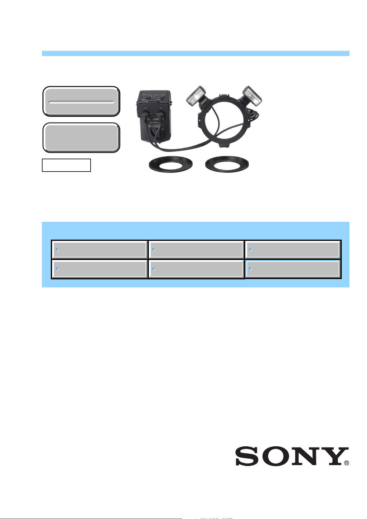
Sony MACRO TWIN HVL-MT24AM User manual

SERVICE MANUAL
Link
Link
Revision History
Revision History
How to use
Acrobat Reader
How to use
Acrobat Reader
Sony Corporation
HVL-MT24AM
SERVICE NOTE
SPECIFICATIONS
FRAME SCHEMATIC DIAGRAM
DISASSEMBLY REPAIR PARTS LIST
ADJUSTMENTS
HVL-MT24AM
Ver. 1.3 2015.06
MACRO TWIN FLASH KIT
2015F08-1
© 2015.06
Published by Sony Techno Create Corporation9-852-155-14
US Model
Canadian Model
AEP Model
Chinese Model
E Model
Revised-2
Replace the previously issued
SERVICE MANUAL 9-852-155-13
with this Manual.

— 2 —
HVL-MT24AM
SPECIFICATIONS
The macro twin flash kit provides flexible lighting for macro nature photography. It is ideal for close-up photography of flowers, insects, small objects,
and so on.
• Freedom to change the attachment position and angle of the flashtube enables more expressive photography.
• Attaching two-length adjustable arms between the twin flash units and holders makes it possible to change the lighting for high magnification
close-up photography.
• Using the supplied diffuser enables softer lighting.
• The supplied wide panel expands flash coverage to a focal length of 24 mm.
• Modeling flash function can check shadows before photographing.
Guide number
Normal flash (ISO 100)
Power 1 tube 2 tubes Wide Diffuser
level panel
1/1 17 24 11 7
1/2 12 17 8 5
1/4 8.5 12 5.6 3.5
1/8 6 8.5 4 2.5
1/16 4.2 6 2.8 1.8
1/32 3 4.2 2 1.3
1/64 2.1 3 1.4 0.9
Wide panel and diffuser is for one tube.
Frequency/Repetition
Nickel-
Alkaline Lithium hydride
(1550 mAh)
Frequency (sec) 0.2~6 0.2~6 0.2~5
Repetition (times) 200~4000 500~10000 150~3000
• Repetition is the approximate number of times that are
possible before a new battery is completely dead.
Flash coverage
Flash Twin Wide Diffuser
coverage flash panel
Vertical 45 °60 °90 °
Horizontal 60 °78 °90 °
Continuous flash performance
40 flashes at 5 flashes per second
(Power level 1/32, nickel-metal hydride battery)
Flash control
Flash control using pre-flash, TTL direct metering,
Manual flash
Dimension (Approx.)
Macro flash controller
68 ×123 ×91 mm (2 3/4 ×4 7/8 ×3 5/8 in.) (w ×h ×d)
Twin flash unit
43 ×41 ×37 mm (1 3/4 ×1 5/8 ×1 1/2 in.) (w ×h ×d)
Mass (Approx.)
Macro flash controller 235 g (8.3 oz.) (without batteries)
Twin flash unit 33 g (1.2 oz.) (per twin flash unit)
Operating temperature
0 °C to 40 °C (32 °F to 104 °F)
Included items
Macro flash controller (1), Twin flash unit (2), Holder (1),
Arm (2), Adaptor ring ø 49mm (1),
Adaptor ring ø 55mm (1), Wide panel (2), Diffuser (2),
Cord reel (2), Controller case (1), Flash case (1),
Set of printed documentation
Functions in these operating instructions depend on testing conditions
at our firm.
Design and specifications are subject to change without notice.

—3 —
HVL-MT24AM
TABLE OF CONTENTS
Section Title Page
1. SERVICE NOTE
1-1. Chemicals ······································································· 1-1
1-2. Exterior Parts ·································································· 1-1
1-3. Unleaded Solder ····························································· 1-1
1-4. Safety Check-out ···························································· 1-2
2. DISASSEMBLY
2-1. Disassembly ··································································· 2-2
3. FRAME SCHEMATIC DIAGRAM
3-1. Frame Schematic Diagram ············································· 3-1
4. REPAIR PARTS LIST
4-1. Exploded Views ······························································ 4-1
4-2. Supplied Accessories ······················································ 4-3
5. ADJUSTMENTS
5-1. Preparations ···································································· 5-1
5-2. Initialization of EEPROM (Writing of Initial Value) ·····5-4
5-3. Charging Voltage Adjustment ········································· 5-6
5-4. Full-charge Voltage/Stop Charge Voltage Check ··········· 5-8
5-5. Assist Mode ···································································· 5-9
5-6. Error Code List ····························································· 5-12

1-1
HVL-MT24AM
1. SERVICE NOTE
1-1. Chemicals
Some chemicals used for servicing are highly volatile.
Their evaporation caused by improper management affects your health and environment, and wastes resources.
Manage the chemicals carefully as follows.
•Store chemicals sealed in a specific place to prevent from exposure to high temperature or direct sunlight.
•Avoid dividing chemicals into excessive numbers of small containers to reduce natural evaporation.
•Keep containers sealed to avoid natural evaporation when chemicals are not in use.
•Avoid using chemicals as much as possible. When using chemicals, divide only required amount to a small plate from the container and
use up it.
1-2. Exterior Parts
Be careful to the following points for exterior parts used in this unit.
•Use a piece of cleaning paper or cleaning cloth for cleaning exterior parts. Avoid using chemicals.
Even if you have to use chemicals to clean heavy dirt, don’t use paint thinner, ketone, nor alcohol.
•Insert the specific screws vertically to the part when installing a exterior part.
Be careful not to tighten screws too much.
1-3. Unleaded Solder
This unit uses unleaded solder.
Boards requiring use of unleaded solder are printed with the lead free mark (LF) indicating the solder contains no lead.
(Caution: Some printed circuit boards may not come printed with the lead free mark due to their particular size.)
: LEAD FREE MARK
Be careful to the following points to solder or unsolder.
•Set the soldering iron tip temperature to 350 °C approximately.
If cannot control temperature, solder/unsolder at high temperature for a short time.
Caution: The printed pattern (copper foil) may peel away if the heated tip is applied for too long, so be careful!
Unleaded solder is more viscous (sticky, less prone to flow) than ordinary solder so use caution not to let solder bridges
occur such as on IC pins, etc.
•Be sure to control soldering iron tips used for unleaded solder and those for leaded solder so they are managed separately. Mixing
unleaded solder and leaded solder will cause detachment phenomenon.

1-2
HVL-MT24AM
1-4. SAFETY CHECK-OUT
After correcting the original service problem, perform the following safety checks before releasing the set to the customer.
1. Check the area of your repair for unsoldered or poorly-soldered connections. Check the entire board surface for solder splashes and
bridges.
2. Check the interboard wiring to ensure that no wires are “pinched”or contact high-wattage resistors.
3. Look for unauthorized replacement parts, particularly transistors, that were installed during a previous repair. Point them out to the
customer and recommend their replacement.
4. Look for parts which, through functioning, show obvious signs of deterioration. Point them out to the customer and recommend their
replacement.
5. Check the B+ voltage to see it is at the values specified.
6. Flexible Circuit Board Repairing
•Keep the temperature of the soldering iron around 270 °C during repairing.
•Do not touch the soldering iron on the same conductor of the circuit board (within 3 times).
•Be careful not to apply force on the conductor when soldering or unsoldering.
SAFETY-RELATED COMPONENT WARNING!!
COMPONENTS IDENTIFIED BY MARK 0OR DOTTED LINEWITH
MARK 0ON THE SCHEMATIC DIAGRAMS AND IN THE PARTS
LIST ARE CRITICAL TO SAFE OPERATION. REPLACE THESE
COMPONENTS WITH SONY PARTS WHOSE PART NUMBERS
APPEAR AS SHOWN IN THIS MANUAL OR IN SUPPLEMENTS
PUBLISHED BY SONY.
ATTENTION AU COMPOSANT AYANT RAPPORT
À LA SÉCURITÉ!
LES COMPOSANTS IDENTIFÉS PAR UNE MARQUE 0SUR LES
DIAGRAMMES SCHÉMATIQUES ET LA LISTE DES PIÈCES SONT
CRITIQUES POUR LA SÉCURITÉ DE FONCTIONNEMENT. NE
REMPLACER CES COMPOSANTS QUE PAR DES PIÈSES SONY
DONT LES NUMÉROS SONT DONNÉS DANS CE MANUEL OU
DANS LES SUPPÉMENTS PUBLIÉS PAR SONY.
CAUTION
Danger of explosion if battery is incorrectly replaced.
Replace only with the same or equivalent type.

2-1
HVL-MT24AM
2. DISASSEMBLY
Cut and remove the part of gilt
which comes off at the point.
(Be careful or some
pieces of gilt may be left inside)
NOTE FOR REPAIR
•Make sure that the flat cable and flexible board are not cracked of bent at the terminal.
Do not insert the cable insufficiently nor crookedly.
•When remove a connector, dont’pull at wire of connector. It is possible that a wire is snapped.
•When installing a connector, dont’press down at wire of connector.
It is possible that a wire is snapped.
•Do not apply excessive load to the gilded flexible board.
DISCHARGING OF THE CHARGING CAPACITOR ONTHE PC BOARD SET, D
The charging capacitor of the PC board set, D is charged up to
the maximum 330 V potential.
There is a danger of electric shock by this high voltage when the
capacitor is handled by hand. The electric shock is caused by
the charged voltage which is kept without discharging when the
main power of the unit is simply turned off. Therefore, the
remaining voltage must be discharged as described below.
Preparing the Short Jig
To preparing the short jig, a wire is attached to each end of a
resistor of 1 kΩ/1 W (1-215-869-11).
Wrap insulating tape fully around the leads of the resistor to
prevent electrical shock.
1 kΩ/1 W
Wrap insulating tape.
R:1 kΩ/1 W
(Part code: 1-215-869-11)
Note: High-voltage cautions
Discharging the Capacitor
Short-circuit between the two points
with the short jig about 10 seconds.
Do both A and B.

2-2
HVL-MT24AM
2-1. DISASSEMBLY
2-1-1. BATTERY CASE UNIT AND SHOE FOOT UNIT
A
C
C
B
(See Page 3-2.)
(Note 1)
B
A
D
EXPLODED VIEW
HELP01
HELP03
HELP02
2Side Rubber
7
Battery Lid
Set
0
PC Board
Set (D)
!- Battery Case Unit
8Bounce Shaft (A) Set
9
Bounce
Shaft (B)
![ Cover (D) Set
!] PC Board
Set (G)
!= Connector
Socket Set
6Cover (C) Set
1Shoe Foot Unit
4Cover (B)
5Click
Connector
Cap (A)
Spacer
!\ Dials
!; Cover (A) Set 3Side Rubber
Note 1
Refer to page 2-1" Discharging of the charging capacitor on the PC board set, D ",
when discharging the capacitor.
D
HELP03

HVL-MT24AM
HELP
HELP
Note for assembling and grease applying positions are shown.
HELP01
Apply the grease (G-85) to the instruction part as shown in the figure.
Grease (G-85): J-6082-626-A
HELP02
Apply the grease (G-85) to the instruction part as shown in the figure.
Grease (G-85): J-6082-626-A
Apply the grease (G-85)

3-1
HVL-MT24AM
3. FRAME SCHEMATIC DIAGRAM
3-1. FRAME SCHEMATIC DIAGRAM
Ver 1.1 2007.01
41532
5
2
4
3
6 5 4
433 0 7 61 2
4321
2
0
6
8
2
90
0
0 1
4
42
PC Board Set (G)
1/64
(B) (A) (B) CM(B)
(-)
(+)
CUT1
CM(A)
(A)
SW6
SW8
CN10
1
CN9
1
1
CN5
CN2
CN1
CN3
CN31
SW7
N34
F-1
1/1 1/1
1/64
PC Board Sst (A)
Shoe Foot Unit
Black
Brown
Red
Orange
Yellow
Green
Blue
Violet
Gray
White
Pink
0
1
2
3
4
5
Color No. No.Color
6
7
8
9
-
Abbreviation number
of the wire color
Connector Socket Set
PC Board (C) PC Board Set (D)
Battery Case Unit
Twin Flash Unit
Trigger
Trigger
Condutive Tape
Xe Tube
Reflector
GND
We+ We-
9
26
0
F2
F3 F1
SW
G
1
CN2
1
1
1
CN8
CN1
CN3
CN4
CN4
1
1
1
CN7
CN6
CN6CN7
Cover (D) Set
Cover (D) Set
Cover (A) Set

4-1
HVL-MT24AM
4. REPAIR PARTS LIST
4-1. EXPLODED VIEWS
4-1-1. BATTERY CASE UNIT AND SHOE FOOT UNIT
DISASSEMBLY
Ref. No. Part No. Description
1 2-691-226-01 RUBBER, SIDE
2 2-691-230-01 TAPE(A)
3 2-693-284-01 SCREW(M1.4X3.0)
4 X-2176-749-1 COVER(A) SET
5 3-095-598-01 PLATE, CLICK
6 3-095-597-01 BRUSH
7 3-095-626-01 SCREW(1.4X2.5 EB)
8 3-095-596-01 DIAL
9 X-2176-756-1 PC BOARD SET, G
10 X-2176-750-1 SOCKET SET, CONNECTOR
11 3-095-591-01 CAP(A), CONNECTOR
12 3-095-627-01 SCREW(2X4.5EB-TR)
13 2-691-288-01 SPACER
014 X-2176-755-1 PC BOARD SET, D
NOTE:
•-XX and -X mean standardized parts, so they may
have some difference from the original one.
•Items marked “*”are not stocked since they are
seldom required for routine service. Some delay
should be anticipated when ordering these items.
•The mechanical parts with no reference number in
the exploded views are not supplied.
15 3-095-595-01 COVER(B)
16 X-2148-367-1 LID SET, BATTERY
17 X-2176-752-1 CASE UNIT, BATTERY
18 2-691-235-01 NUT
19 2-691-234-01 SCREW(M2.0X3/5)
20 X-2176-751-1 COVER(C) SET
21 3-095-592-01 PANNEL
22 X-2176-754-1 FOOT UNIT, SHOE
23 2-691-233-01 SCREW(M2.0X4.0)
24 2-691-232-01 JOINT
25 2-693-277-01 SHAFT(B), BOUNCE
26 X-2148-453-1 SHAFT(A) SET, BOUNCE
27 2-693-236-01 CLICK
28 2-691-231-01 CLICK SP
29 3-093-593-01 STICKER, COUNTRY OF ORIGIN
Ref. No. Part No. Description
The components identified by
mark 0or dotted line with
mark 0are critical for safety.
Replace only with part num-
ber specified.
Les composants identifiés par une
marque 0sont critiques pour la
sécurité.
Ne les remplacer que par une pièce
portant le numéro spécifié.
A
C
C
B
(See Page 4-2.)
B
A
D
D
1
2
8
3
4
56
3
9
7
12
29
15
12
3
21
7
5
6
7
10
11
12
13
14
19
20
21
23
22 23
18 16
18
19
17
24
25
24
19
19
27 28 26
12
3

4-3
HVL-MT24AM
4-2. SUPPLIED ACCESSORIES
Checking supplied accessories.
Other accessories
2-889-493-01 MANUAL, INSTRUCTION
(JAPANESE, ENGLISH, FRENCH) (J, US, CND)
2-889-493-11 MANUAL, INSTRUCTION
(ENGLISH, FRENCH, GERMAN, ITALIAN, DUTCH) (AEP)
2-889-493-21 MANUAL, INSTRUCTION (ENGLISH, PORTUGUESE,
SPANISH, SWEDISH, RUSSIAN) (AEP)
2-889-493-31 MANUAL, INSTRUCTION
(ENGLISH, ARABIC, TRADITONAL CHINESE,
SIMPLIFIED CHINESE, KOREAN) (AEP. CH)
•Abbreviation
CND :Canadian model
CH :Chinese model
TWIN FLASH UNIT
1-479-857-11
ARM
2-695-321-01
HOLDER
2-695-322-01
WIDE PANEL
2-695-323-01
CORD REEL
2-695-326-01
FLASH CASE
2-695-328-01
DEFFUSER
2-695-324-01
ADAPTOR RING (ø49mm)
2-695-325-01
ADAPTOR RING (ø55mm)
2-695-376-01
CONTOLLER CASE
3-098-238-01
ADAPTOR RING (ø62mm)
4-564-084-01
Ver. 1.3 2015.06
The changed portions from
Ver. 1.2 are shown in blue.

5-1
HVL-MT24AM
5. ADJUSTMENTS
Note: After the service repair, perform the adjustments referring to this section.
5-1. PREPARATIONS
5-1-1. Adjusting Items when Replacing the Parts
When replacing the following part, perform the described check/adjustment.
When replacing the Cover-D Assy:
•5-2. INITIALIZATION OF EEPROM (WRITING OF INITIAL VALUE)
•5-3. CHARGING VOLTAGE ADJUSTMENT
•5-4. FULL-CHARGE VOLTAGE/STOP CHARGE VOLTAGE CHECK
•5-5-2. LCD/LED Displays Check
When replacing the PC board set, D or battery case unit:
•5-3. CHARGING VOLTAGE ADJUSTMENT
•5-4. FULL-CHARGE VOLTAGE/STOP CHARGE VOLTAGE CHECK
•5-5-2. LCD/LED Displays Check
When disassembling/assembling the flash:
•5-5-2. LCD/LED Displays Check

5-2
HVL-MT24AM
5-1-2. List of Service Tools and Equipments
•DC Power Supply
•Digital Multimeter
•Camera DSLR-A100
Fig. 5-1-1
Note 1: Personal Computer (PC)
OS: Windows2000 Professional/XP
MEMORY: 40 M Byte or more recommended
Hard disk free area: 15 M Byte or more recommended
USB terminal: Standard equipment
MONITOR: Monitor of VGA or more that can display color of 32,000 or more.
Note 2: Attach the power supply adaptor as shown in Fig. 5-1-2.
Fig. 5-1-2
Personal computer
(Note 1)
USB cord with
connector
1-833-062-11
Power supply
adaptor
J-6082-602-A
(Note 2)
J-1 J-2 J-3
Power supply adaptor
Connect the IC clips to the battery contact plate
ensuring the clip pinches the contact plate
not the plastic retainer along the side edges of the plate.

5-3
HVL-MT24AM
5-1-3. Flash Adjustment Program
The flash adjustment program is required for the check/adjustment after the service repair.
Prepare/start the flash adjustment program with the following steps.
Equipment
• Personal Computer (PC)
• Camera DSLR-A100
• USB Cord With Connector
• Flash Adjustment Program
Note: Flash Adjustment Program is downloadable from the ESI homepage.
1. Installation of the Flash Adjustment Program
For installation of the flash adjustment program, refer to the link “• Preparing the DSLR-A100 adjustment program” described on
the top cover of the camera DSLR-A100 service manual “9-852-130-5 ”.
2. Start the Flash Adjustment Program
1) Connect the flash to the camera.
2) Turn the POWER switch of the camera to OFF, then connect the camera and PC with the USB cord with connector.
3) Set the mode dial of camera to “M”.
4) Turn the POWER switch to ON while pressing the shutter button halfway down with pressed the button of controller keys and
MENU buttons.
5) Check that the remaining number of recordable images on the LCD monitor is “BBBB”.
Note: When “BBBB” is displayed, the camera activates in the adjustment mode.
6) Start the flash adjustment program “FlashAdjustment.exe”.

5-4
HVL-MT24AM
5-2. INITIALIZATION OF EEPROM (WRITING OF INITIAL VALUE)
Note: When replacing the PC board set, A, perform the EEPROM initialization before any adjustment.
If dialog box of error code appears during the initialization, check the reason of error referring to page 5-12.
Equipment
•Personal Computer (PC)
•Camera DSLR-A100
•USB Cord With Connector
•Flash Adjustment Program
Note: Flash Adjustment Program is downloadable from the ESI homepage.
1. Preparations
1) Connect the checking flash to the camera.
2) Start the flash adjustment program “FlashAdjustment.exe”referring to “5-1-3. Flash Adjustment Program”.
Fig. 5-2-1
2. Initializing Method
1) Select the “HVL-MT24AM/Macro Controller”from the pull down menu of the flash adjustment program, then click the [Connect]
button.
Note: Click the [End] button to terminate the flash adjustment program.
Fig. 5-2-2
2) When checking message window “You select HVL-MT24AM/Macro Controller”appears, click the [Yes] button.
Fig. 5-2-3
3) When adjustment menu window appears, click the [EEP Initialize] button.
Note: Click the [Exit] button to disconnect the USB connection of PC.
Fig. 5-2-4

5-5
HVL-MT24AM
4) Click the [Initialize] button.
Fig. 5-2-5
5) When checking message window “Do you really want to initialize EEPROM?”appears, click the [Yes] button.
Fig. 5-2-6
6) When completion message “Done.”appears after initialization, click the [OK] button.
Fig. 5-2-7
7) When the initialization is completed, click the [Exit] button to go back the adjustment menu.
8) Perform the “5-3. CHARGING VOLTAGE ADJUSTMENT”continuesly.
Note: Please adjust the charge voltage when you do the initial value writing. (The adjustment value is initalized.)
Fig. 5-2-8

5-6
HVL-MT24AM
5-3. CHARGING VOLTAGE ADJUSTMENT
Note: If dialog box of error code appears during the adjustment, check the reason of error referring to page 5-12.
Equipment
•Personal Computer (PC)
•Camera DSLR-A100
•USB Cord With Connector
•Flash Adjustment Program
Note: Flash Adjustment Program is downloadable from the ESI homepage.
•DC Power Supply
•Digital Multimeter
•Power Supply Adaptor
1. Preparations
1) Set the equipments as shown in the Fig. 5-3-1.
Note: For connection method of power supply adaptor, refer to page 5-2.
Set the detection pin of the digital multimeter to the DC voltage detecting point.
(The probe (-) of the digital multimeter can be connected to the negative line of the DC power supply.)
Fig. 5-3-1
2) Set the voltage and current of the DC power supply to “5.8V, 1.8A”.
3) Start the flash adjustment program “FlashAdjustment.exe”referring to “5-1-3. Flash Adjustment Program”.
Fig. 5-3-2
Personal Computer
Digital multimeter
Power supply adaptor USB cord with connector
DC power supply
(5.8 V, 1.8 A)
The probe (–) of the digital multimeter can be connected
to the negative line of the DC power supply.
Camera
Table of contents
Other Sony Camera Flash manuals

Sony
Sony HVL-FDH2 User manual

Sony
Sony HVL-FSL1 User manual

Sony
Sony HVL-F20AM User manual

Sony
Sony HVL-FDH4 User manual

Sony
Sony HVL-F56AM User manual

Sony
Sony HVL-RL1 User manual

Sony
Sony HVL-F60RM2 Reference guide

Sony
Sony HVL-F60RM2 User manual

Sony
Sony HVL-F20AM User manual

Sony
Sony HVL-F20S User manual

Sony
Sony Alpha HVL-MT24AM User manual

Sony
Sony HVL-F36AM - Flash For Alpha DSLR User manual

Sony
Sony HVL-F20S User manual

Sony
Sony HVL-F56AM User manual

Sony
Sony HVL-F20S User manual

Sony
Sony HVL-F10 User manual

Sony
Sony HVL-F43AM User manual

Sony
Sony HVL-F32M User manual

Sony
Sony HVL-F46RM User manual

Sony
Sony HVL-LE1 User manual