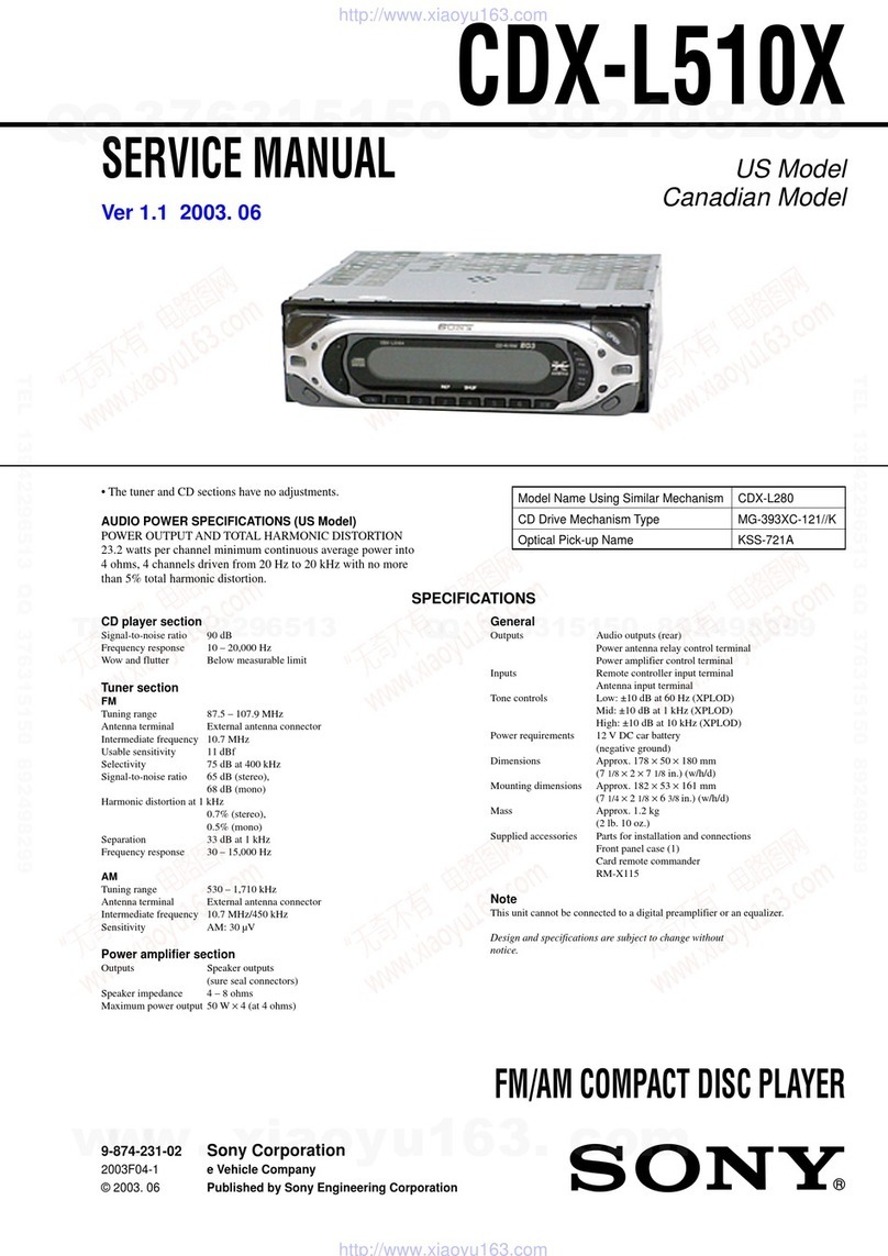
Signal-to-noise ratio 90 dB
Frequency response 10 20,000 Hz
Wow and lutter Below measurable limit
General
Design and Speci ications subject to change without notice.
CD Player Section
FM
Tuning range 87.5 107.9 MHz
Antenna terminal External antenna connector
Intermediate requency 10.7 MHz
Usable sensitivity 11 dB
Selectivity 75 dB at 400 kHz
Signal-to-noise ratio 65 dB (stereo), 68 dB (mono)
Harmonic distortion at 1 kHz 0.7% (stereo), 0.5% (mono)
Separation 33 dB at 1 kHz
Frequency response 30 15,000 Hz
AM
Tuning range 530 1,710 kHz
Antenna terminal External antenna connector
Intermediate requency 10.7 MHz/450 kHz
Sensitivity 30 µV
Outputs Speaker outputs
Speaker impedance 4 8 ohms
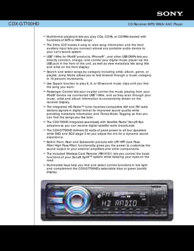
Maximum power output 52 W × 4 (at 4 ohms)
Outputs Power antenna relay control terminal
Inputs Telephone ATT control terminal
Tone controls Bass ±10 dB at 20 Hz
Treble ±10 dB at 20 kHz
Power requirements 12 V DC car battery (negative ground)
Dimensions Approx. 178 × 50 × 177 mm
(7 1/8 × 2 1/8 × 7 in.) (w/h/d)
Mounting dimensions Approx. 182 × 53 × 161 mm
(7 1/4 × 2 × 6 3/8 in.) (w/h/d)
Mass Approx. 1.2 kg
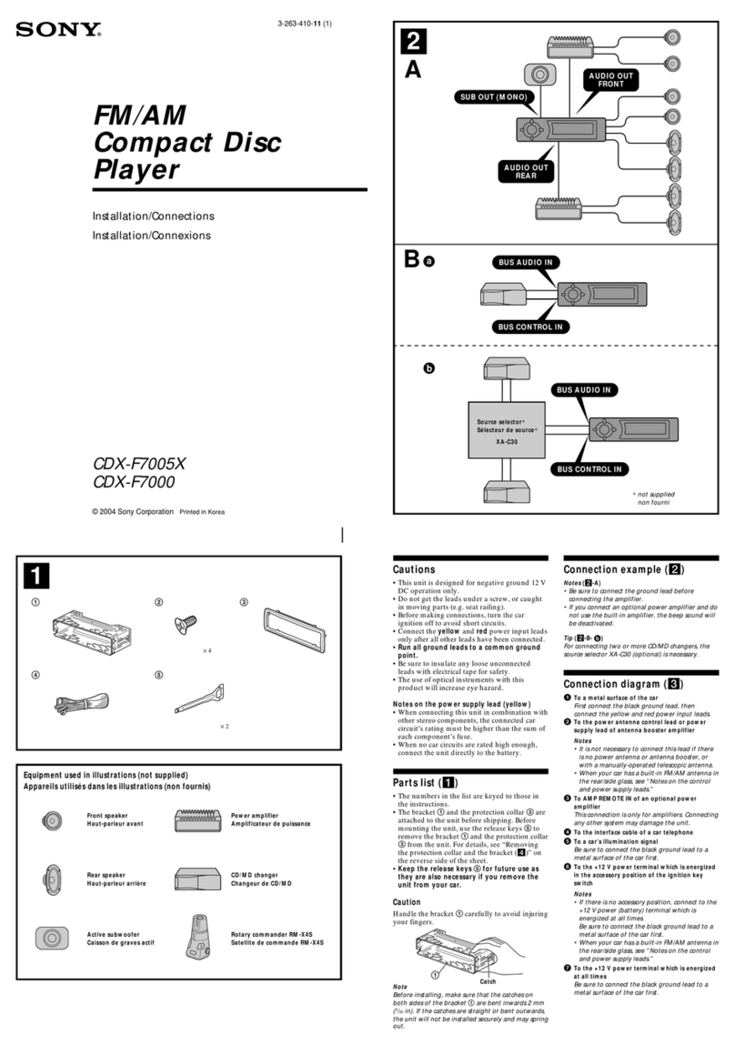
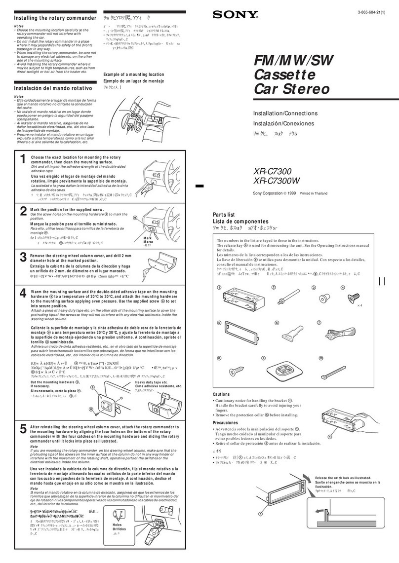
Supplied accessories Parts or installation and connections (1 set)
Front panel case (1)
This unit cannot be connected to a digital preampli ier or an equalizer.
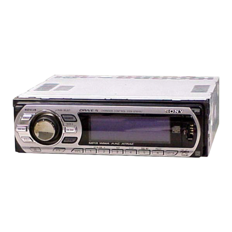
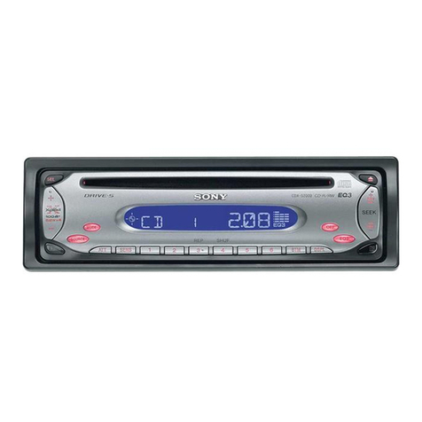
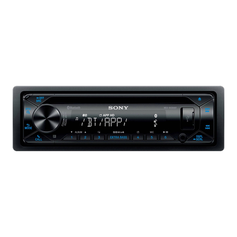
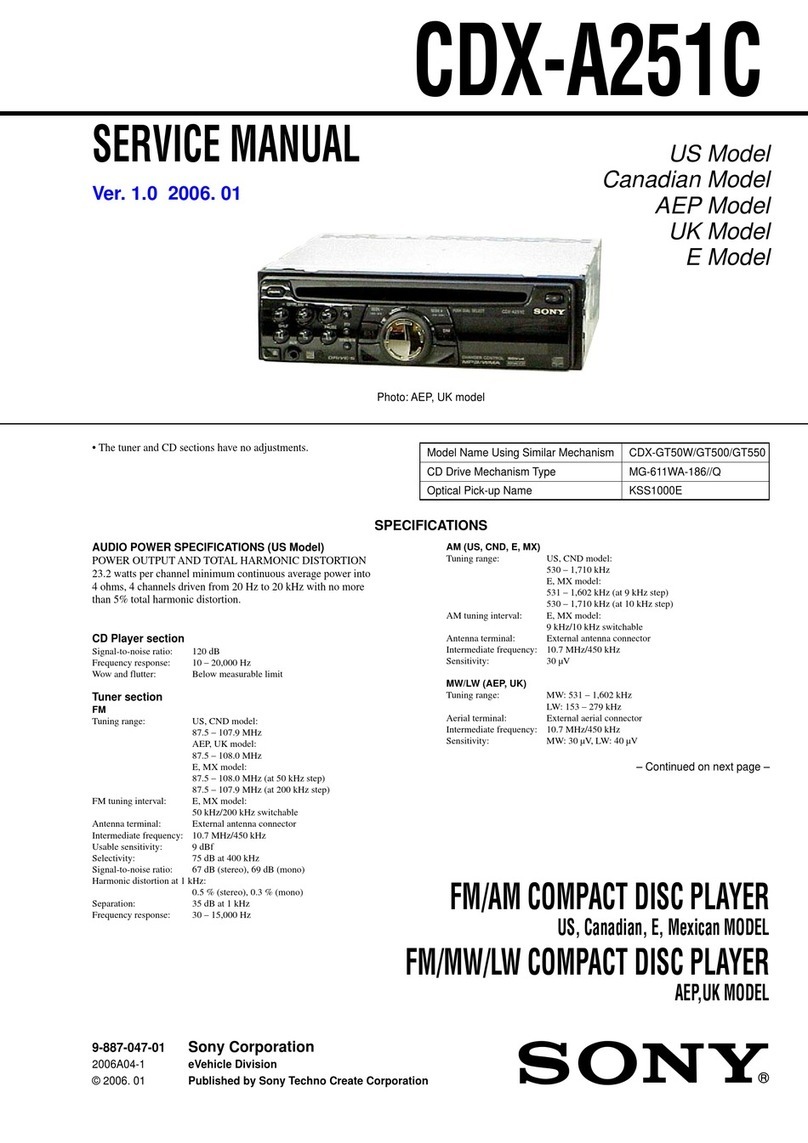
CDX-MP30
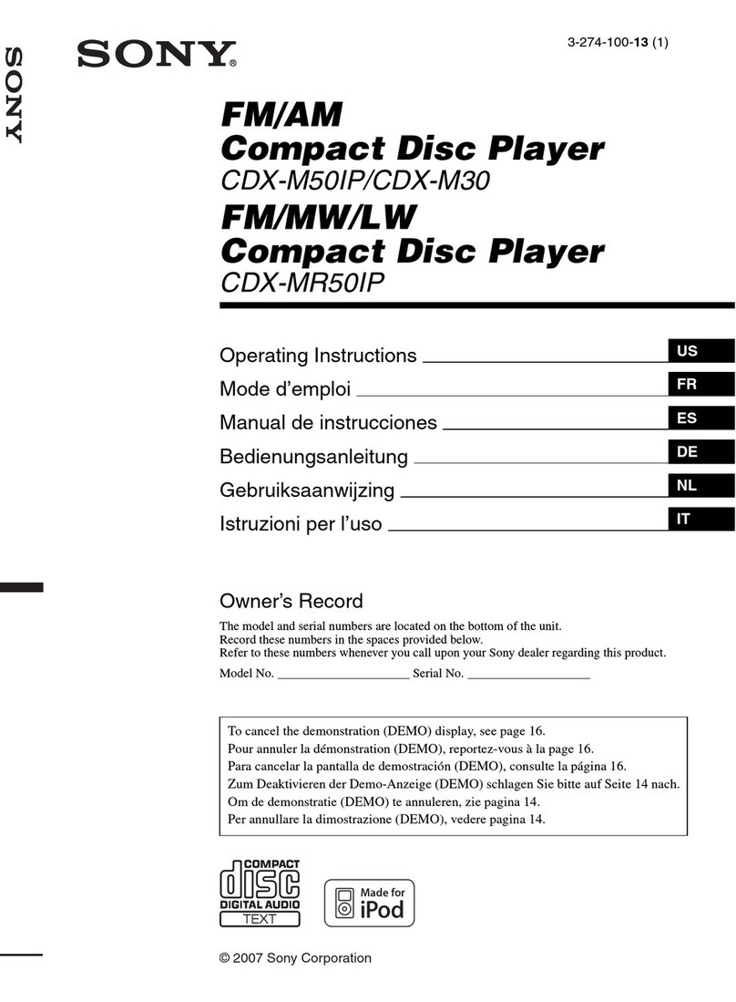
FM/AM Compact Disc Player
Power Amplifier Section
Note
2002 SONY MOBILE
PRODUCT GUIDE
-
CD TEXT®
XM Ready
SSIR-EX Tuner
MP3 & CD-RW Playback
CD/MD Control w/Custom File memory
MBP (My Best Position)
D-Bass
Supplied Wireless Card Remote (RM-X114)
Optional Wired Rotary Remote (RM-X4S)
8 s, 1-Bit D/A Converter
60 Degree Install
18FM + 12AM memory presets
Xplod® Power: 52W x 4
F/R Preouts
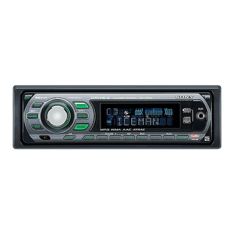
13-segment, 2-color LCD, clock
Dual knob design
Detachable Faceplate
Indicates step-up
MS Section
Audio Power Specifications
POWER OUTPUT AND TOTAL HARMONIC DISTORTION
23 watts per channel minimum continuous average power into 4 ohms, 4 channels driven rom 20 Hz to 20 kHz with no more than 5%
total harmonic distortion.
Plug shown with wires acing viewer.
Pin Number Wire Color Description
1 White Le t ront +
2 Green Le t rear +
3 Purple Right rear +
4 Gray Right ront +
5 Blue/white AMP Remote
6 Blue ANT Remote
7 Red Accessory
8 Black Ground
9 White/black Le t ront -
10 Green/black Le t rear -
11 Purple/black Right rear -
12 Gray/black Right ront -
13 Sky blue ATT
14
15
16 Yellow Battery
Harness Plug Configuration
16
1 2 3 4 5 6 7 8
9 10 11 12 13 14 15
