– 4 –
SECTION 1
GENERAL
TABLE OF CONTENTS
LOCATION OF PARTS AND CONTROLS
6-9. Printed Wiring Board – Main Section – .............................. 43
6-10. Schematic Diagram – Main (1/5) Section – ..................... 45
6-11. Schematic Diagram – Main (2/5) Section – ..................... 47
6-12. Schematic Diagram – Main (3/5) Section – ..................... 49
6-13. Schematic Diagram – Main (4/5) Section – ..................... 51
6-14. Schematic Diagram – Main (5/5) Section – ..................... 53
6-15. Printed Wiring Board – Deck Section – ........................... 55
6-16. Schematic Diagram – Deck Section – .............................. 57
6-17. Printed Wiring Board – Power Section – .........................59
6-18. Schematic Diagram – Power Section – ............................ 61
6-19. Schematic Diagram – Panel Section – .............................63
6-20. Printed Wiring Board – Panel Section – ........................... 65
6-21. Printed Wiring Board –TC/CD Panel-1 Section –........... 67
6-22. Schematic Diagram – TC/CD Panel-1 Section – ............. 69
6-23. Schematic Diagram – HP/Mic Section –.......................... 71
6-24. Printed Wiring Board – HP/Mic Section – ....................... 73
6-25. Printed Wiring Board – CD Motor Section – ...................75
6-26. Schematic Diagram – CD Motor Section –...................... 77
6-27. Printed Wiring Board –Trans Section – ...........................79
6-28. Schematic Diagram – Trans Section – .............................81
6-29. Printed Wiring Board – Surround Section –..................... 83
6-30. Schematic Diagram – Surround Section – ....................... 84
6-31. IC Block Diagrams ........................................................... 85
6-32. IC Pin Functions ............................................................... 92
7. EXPLODEDVIEWS
7-1. Case and Back Panel Section ............................................ 100
7-2. Front Panel Section 1 ........................................................ 101
7-3. Front Panel Section 2 ........................................................ 102
7-4. Chassis Section ................................................................. 103
7-5. TC Mechanism Section-1 (TCM-220WR2) ..................... 104
7-6. TC Mechanism Section-2 (TCM-220WR2) ..................... 105
7-7. TC Mechanism Section-3 (TCM-220WR2) ..................... 106
7-8. CD Mechanism Section
(CDM37L-5BD29AL/CMD37LH-5BD29AL) ................ 107
7-9. Base Unit Section (BU-5BD29AL) .................................. 108
8. ELECTRICAL PARTS LIST ...................................... 109
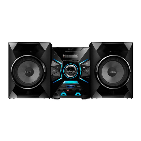
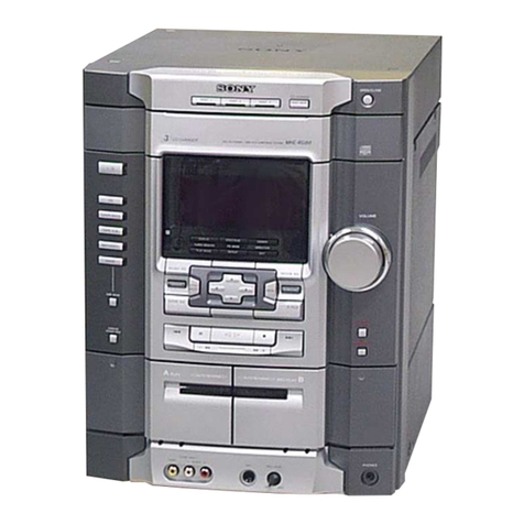
11/u button
2REC button
3t/CLOCK SET button
4DAILY 1 button
5DAILY 2 button
6SLEEP button
7DISPLAY/DEMO button
8SPECTRUMANALYZER button
9Display Window
!º ENTER/NEXT button
!¡ TUNER MEMORY button
!™ TUNING MODE button
!£ TUNER/BAND button
!¢ TUNING (+/–) button
!∞ PTY button
(AEP, UK)
!§ STEREO/MONO button
!¶ Equalizer indicators
!• MIC LEVEL knob
!ª MIC jack
@º DSP button
@¡ WAVE button
@™ PROLOGIC button
@£ KARAOKE PON/MPX button
@¢ P FILE MEMORY button
@∞ PHONES jack
@§ EFFECT button
@¶ FUNCTION button
@• GROOVE button
@ª VOLUME control
#º SUPER WOOFER button
(XB80AV/XB88AV)
#º DBFB button (D890AV/XB55AV)
#¡ GEQ control buttons
#™ GEQ CONTROL button
#£ SUPER W MODE button
(XB80AV/XB88AV)
#¢ ENTER button
#∞ DeckA ª, ·button
#§ DeckA pbutton
#¶ DIRECTION button
#• DOLBY NR button
#ª DeckA 0, )button
$º DeckA 6EJECT button
$¡ Deck B pbutton
$™ Deck B ª, ·button
$£ Deck B 0, )button
$¢ Deck B rREC button
$∞ Deck B Pbutton
$§ CD SYNC button
$¶ H SPEED DUB button
$• Deck B 6EJECT button
$ª 6OPEN button
%º CD ·button
%¡ CD pbutton
%™ CD Pbutton
%£ DISC SKIP button
%¢ DISC1-DISC5 buttons
%∞ NON-STOP button
%§ LOOP button
%¶ FLASH button
%• 1/ALL DISCS button
%ª PLAY MODE button
^º CD 0, )button
^¡ REPEAT button
^™ EDIT button
^£ ≠AMS ±dial
1. GENERAL ..........................................................................4
2. DISASSEMBLY
2-1. Front Panel ........................................................................... 6
2-2. Main Board ........................................................................... 6
2-3. Tape Mechanism Deck ..........................................................7
2-4. Cassette Lid Assembly .......................................................... 7
2-5. CD Lid Assembly ..................................................................8
2-6. CD Mechanism Deck ............................................................8
2-7. Base Unit ..............................................................................8
2-8. Disc Table ............................................................................. 9
3. SERVICE MODE ............................................................10
4. MECHANICAL ADJUSTMENTS ..........................12
5. ELECTRICAL ADJUSTMENTS ............................... 12
6. DIAGRAMS
6-1. Circuit Boards Location ......................................................18
6-2. Brock Diagrams
• Tuner Section (AEP, UK model) ..................................... 19
• Tuner Section (East European, CIS model) ..................... 21
• CD Section ....................................................................... 23
• Deck Section ....................................................................25
• Main Section ....................................................................27
• Power Section .................................................................. 29
6-3. Printed Wiring Board – CD Section –.................................33
6-4. Schematic Diagram – CD Section – ................................... 35
6-5. Schematic Diagram
– Tuner Section – (AEP, UK model)................................... 37
6-6. Printed Wiring Board
– Tuner Section – (AEP, UK model)................................... 39
6-7. Printed Wiring Board
– Tuner Section – (East European, CIS model) ..................40
6-8. Schematic Diagram
– Tuner Section – (East European, CIS model) ..................41
w
w
w
.
x
i
a
o
y
u
1
6
3
.
c
o
m
Q
Q
3
7
6
3
1
5
1
5
0
9
9
2
8
9
4
2
9
8
T
E
L
1
3
9
4
2
2
9
6
5
1
3
9
9
2
8
9
4
2
9
8
0
5
1
5
1
3
6
7
3
Q
Q
TEL 13942296513 QQ 376315150 892498299
TEL 13942296513 QQ 376315150 892498299
http://www.xiaoyu163.com
http://www.xiaoyu163.com
