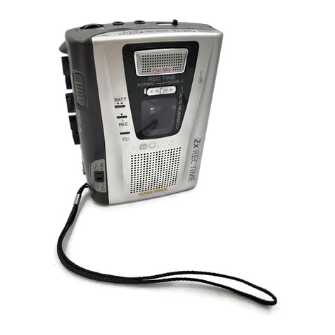
Sony TC-150 User manual

www.SteamPoweredRadio.Com
TABLE
OF
CONTENT
S
Features
...........
,,..,,
..............
.
.......
.
.................................
2
Precautions
..................................
.
...
....
......
..
....
..
......
.......
.......
3
location
and
function
of
controls
....
....
.....
...
.
......................
......
4
Power
sources
.
........
. .
.........
...
..........
..
...
..
.........................
6
Cassette
insertion
.....
.........
.....
..
.
............
..
.......
..
..
.
......
.
....
.....
.
...
9
Recording
from
the
built-in
microphone
...
....
.....
...
....
................
10
Playback
......
..
.....
...
..
......
.........
............
.
......
....
......
...............
12
Recordlng
from
various
sound
sources
...............
......
.....
.......
...
13
Erasing
without
recording
...
..
..
.
...
.......
...
....
..
....
....
.
...
.
..
...
..
......15
Maintenance
.....
..
.......
...
..
..
.
...
.
....
.
.........
....
.......
.
............
.
...
.
....
16
Specifications.
......
....
.......
..
..........
..
...
....
....
.........
......
.....
..
. .17
Optional
accessories
..
....
..
........
...
...............
..
...
...............
.
...
18
Troubleshooting
guide
....
..
.............
.........
......
..
.............
...
... .18
FEATURES
•
Ultimate
recording
simplicity
merely
insert
a
cassette
and
de-
press a
single
button
•
Automatic
shut•off
mechanism
in
the
record
and
playback
mode
.
•
Recording
level
can
be
controlled
automatically
.
•
Cue
and
review
function
to
quickly
locate
any
desired
portion
of
the
tape.
•
Counter·inenial
flywheels
for
stable
tape
speed.
•
Instant
tape
stop
switch
.
•
Built
-i
n
Electret
Condenser
Microphone.
•
Four·way
power
source
operation
:
batteries
. ac
power
with
Sony
AC
Power
Adaptor
(supplied
).
Sony
Rechargeable
Battery
P
ack
BP-28
(optional
).
or
12V
car
battery
with
Sony
Car
Battery
Corti
DCC-127H
(optfonal)
.
2
PRECAUTIONS
•
Do
not
open
the
cabinet.
Refer
servic
i
ng
to
qualified
personnel
only
.
•
Operate
the
set
only
on 6 V
de
.
For
operation
from
house
cu
r-
rent
,
use
the
ac
power
adaptor
supplied
with
this
set
.
For
car
battery
operation
.
use
the
car
battery
cord
recommended
for
th
is
set
.
Do
not
use
any
other
ac
power
adaptor
or
car
battery
cord
•
Disconnect
the
ac
power
adaptor
from
the
ac
wall
out
l
et
when
the
set
is
not
to
be
used
for
an ei,;tended
period
of
time
.
•
When
the
set
is
not
to
be
used
for
a
long
period
of
time
or
is
operated
for
long
periods
on
other
power
sources
.
remove
the
bat
•
teries
to
avoid
set
damage
from
battery
leakage
.
•
Do
not
insta
ll
the
set
in a
location
near
heat
sources
such
as
radiators
or
airducts
,
or
in
a
place
subject
to
direct
sunlight
,
ex·
cessive
dust
,
moisture
,
rain
or
mechanical
shock.
•
Shou
ld
any
liquid
or
solid
object
fall
into
the
mechanism
.
remove
the
batteries
and
disconnect
the
ac
power
adaptor,
and
have
the
set
checked
by
quali
f
ied
personnel
before
operating
it
any
further
.
•
Keeping
the
tape heads
in
a
clean
condition
Is
essential
to
the
proper
operation
of
the
recorder
. For
cleaning
information
,
refer
to
page 16.
•
The
REC
button
cannot
be
dep
ressed
in
the
follow111g cases
Never
depress
the
button
forcibly
.
,
No
cassette
in
the
cassette
compartment
•
The
cassette
Inserted
has
had
the
tabs
removed
,
The
►
,
,....
or
-
button
has
been
depressed
.
•
If
you
have
any
question
or
problem
concerning
your
set
thal
is
not
covered
In
this
booklet
, please
consult
the
nearest
Sony
Ser
-
vice
Station
authorized
to
service
tape
recorde
rs
(in
U.S.A )
or
th
e
nearest
Sony
Factory
Service
Station
(In
CANADA
).
3

www.SteamPoweredRadio.Com
LOCATION
AND
FUNCTION
OF
CONTROLS
O
Battery
Compartment
(rear): See
page
6.
6 EJECT
Button
: Depress
to
pop
up
the
cassette,
after
opening
the
lid.
@
Tape
Counter
and
Reset
Button
:
Use
the
counter
for
indexing
the
tape
contents.
Before
recordfng
,
set
the
counter
to
000
by
pushing
the
Reset
Button
.
The
figures
of
the
counter
change
as
the
tape
passes
.
Make
a
note
of
the
figures
and
the
program
being
recorded
.
Later
on,
the
desired
program
can
be
rapidly
lo-
cated
by
using
the
-
or
-
button
.
O 0 Cassette
Compartment
Lid
and
Catch
:
Open
the
lid
by
lifting
the
Catch
.
@ EARPHONE
Jack
:
For
private
listening
with
an
earphone
or
connecting
to
another
tape
recorder
.
fj
REMOTE
Control
Jack
: For
remote
stop
start
op
e
ration
during
recording
or
playback
by
connecting
the
Sony
Remote
Control
RM-15
(optional)
, Foot
Switch
FS
-6
(optional).
or
a
Sony
two-pin
plug
microphone.
4
•
To
stop
the
tape
for
an
extended
time,
use
the
■
but1on
on
the
recorder.
©
Microph:ine
Input
Jack
MIC
":
For
recording
with
an
external
microphone.
or
from
a
TV
,
radlo
,
telephone
or
another
tape
re-
corder.
(1)
Battery
Check
Button
_
BATT
CHECK
-:
While
recording
depress
the
button
and
observe
the
REC
BATT
meter
to
check
the
battery
condit
ion
. See
page
7.
CE)
Record'
Battery
Meter
REC
BATT
=:
While
recording.
the
point
-
er
swings
to
indicate
the
input
sound
signal.
In
the
other
modes
,
it
shows
the
battery
condition.
a,
External
P
ower
Input
Jack
=DC
IN
6 V : For
operation
from
an
external
power
source.
(D
Record
Music
Speech
Selector
REC MUSIC SPEECW
MUSIC
: use
for
music
recordings
.
This
switch
position
partially
retains
the
dynamic
range
of
musical
sounds
.
SPEECH:
use
for
recording
conversation
or
telephone
recordings
This
position
keeps
loud
and
quiet
sounding
voices
at
nearly
the
same
level.
®
Rewind
Review
Button
- - REVIEW
=:
Depress
to
rewind
the
tape
. For
review
function
,
refer
to
page
11.
m
Stop
Button
■
":
Depress
to
stop
the
tape
anJ
to
release
the
l
ocked
buttons.
©
Playback
Button
► : Depress
to
play
back
the
tape
.
© Fast
Forward
Cue
Button
_CUE -Depress
to
rapidly
ad-
vance
the
tape.
For
cue
function.
refer
to
page
11
.
CD
Record
Button
REC
=.
Depress
to
record.
•
It
is
possible
to
record
with
the
REC
button
and
►
button
locked
.
but
this
is
not
necessary
with
the
single-butto;i
recording
system
of
the
TC-150
.
©
Built-in
Microphone
©
Instant
Stop
Switch
START
STO?
For
instant
tape
stop
dur-
ing
playback
or
recording
•
To
stop
the
tape
for
an
extended
time
, use
the
■
button
on
the
recorder
.
•
When
using
a
mrcrophone
with
a
remote
tape
stop
start
capa
-
bility
or
a
remote
control
switch
,
the
Instant
Stop
Switch
is
not
operative.
@l)
Playback
Volume
Control
PB
VOL
-=·
Turn
in
the
arrow
di-
rection
for
more
volume
during
playback.
5

www.SteamPoweredRadio.Com
Ba
tteries
Ba
ttery
inst
al
la
ti
on ;
0
Re
move
the
s
lidin
g the
notch,
and
pulling
1t
outwards
.
POWER
SOURCES
Replace
by
sliding in
th
e r
ecorder
unti
l
the
not
ch
engages
6 Insert
four
batteries size AA m the case wi
th
c
orre
ct
po
l
arity
and
in
order
as ill
ustrated
. rPress
flat
side
of
b
at
ter
y 2
against
the
spring
2
4
Press
flat
side
of
battery
4
against
th
e
battery
3.
•
Make
sure
that
the
ac
power
adap
t
or
and
optional
car
battery
cord
are
disconnected
from
the
recorder
If
not
,
the
set
cannot
be
operated
on
the
internal
batteries
•
When
the
set
is
not
to be u
sed
for
a
long
period
of
time
or
is
to
be
operated
extensively
on
other
power
sources
,
remove
the
bat-
teries
to
avoid
set
damage
caused
by
battery
leakage
and
corro
s1on
6
Ba
tt
ery
life
; A
bou
t 2.5
hours
of
cont
i
nuous
r
ecording
from
the
Bu
ilt-in
M
icrophone
1s
possible
us
ing
Sony
Super
Batteri
es
size
AA
Intermittent
use w
ill
prolong
the
useful
battery
lite
.
To
check
bat
t
ery
co
ndition
:
During
recording
,
observe
the
REC
B
ATT
meter
deflection
by
depressing
the
BATT
CHECK
butto
n
During
the
other
modes
,
observe
the
meter
deflection
while
depres
-
sing
the
►
,
- ,
or
◄◄
button
If
the
po
i
nter
of
th
e
meter
stays
out
of
the
green
zone,
replace
all
the
batteries
with
new
ones
.
•
Before
cr
i
tical
recordings
,
checking
the
batte
r
ies
in
recording
mode
is re
com
m
ended
lr- ~~ + Good
battery
l..:===========::::::J
1
condition
~ /~ +1
J
Replace
'-===
======:=::;the
batteries
House
Current
Insert
the
supplied
AC
Powe
r A
::la
pt
or
Into
the
recorder
DC
IN
6 V
jack
,
and
connect
the
othe
r
end
to
a
wall
outlet
(
120
V)
.
When
the
ac
power
adaptor
is
connected
to
the
DC IN 6 V
jack,
th
e
In
te
r•
nal
batteries
are
au
tomatical
ly
disconnected.
6
to
a
wa
ll
outlet
O
to
DC
IN
6V
[
(j]t-
L----
-cE....:P
E;f
o
120V AC
Powe
r
Adaptor
7

www.SteamPoweredRadio.Com
Rechargeable
Ba
ttery
Pack
Install
the
Sony
Rechargeable
Battery
Pack
BP-
28
(optional)
in
•
stead
of
the
Battery
Case,
The
fully
charged
BP-
28
allows
approx.
3.5
hours
of
continuous
recording
from
the
Built-in
Microphone.
Before
using
,
charge
the
battery
pack
as
follows
:
O
Install
the
BP-
28
in
the
Banery
Compartment
.
f)
Connect
the
supplied
AC
Powar
A::laptor
to
the
recorder
DC
IN
6 V
jack
and
to
a
suitab
le
outlet
Charging
will
begin
.
•
Charging
time
is
about
4.5
hours
.
•
The
recorder
c3n
be.
ope
r
ated
w~
ile
charging
,
although
more
charging
time
will
be
needed.
•
When
charging
is
comp
l
eted
,
remove
the
ac
power
adaptor
to
avoid
overcharging
the
battery
pack.
•
While
the
vo
lt
age
of
the
rechargeable
battery
pack
can
be
check
-
ed
in
the
same
way
as
for
regular
batteries,
this
is
no
t a
reliable
index
of
the
remaining
operat
i
ng
life
,
since
a
nickel-cadmium
bat-
tery
wil
l
furnish
a
nearly
constant
voltage
up
to
the
end
of
its
capacity
,
and
then
drop
quickly
to
a
low
value
,
Keeping
a
record
of
the
time
in
actual
use
is
the
most
reliable
measure
of
remaining
battery
life
when
using
nickel-cadmium
batterles
.
12
V
Car
Ba
ttery
Using
the
Sony
Car B
attery
Cord DCC
-1
27H
(optional)
,
connect
the
recorder
DC
IN
6 V
jack
to
the
cigarette
lighter
socket
of
a
car
.
For
further
details
,
refer
to
the
instruction
manual
of
the
DCC-
127H.
DCC
127H
l
10
DC IN
6V
8
CASSETTE
INSERTION
Before
inserting
a
cassette,
take
up
any
slack
in
the
tape
by
i
nserting
a
thick
pencil
into
the
hub
of
the
cas-
sette
and
turning
it
a
few
times
.
0 Open the Cassette
Compartment
Ltd
by
lifting
the Catch.
6 Place a cassette in
the
comparimen
t as illustrated wi
th
the de-
sired
si
de
, A
or
B,
upward.
T
he
letter
A on the
Sony
cassette Is
embossed
to
help you distinguish
that
side
ot
the casset1e in a
dimly
lighted
area
0 Close
the
lid.
Avoid
touching
the
tape surfaces.
• Make sure
that
the
portion
of
the
tape
to
be
played back
or
recorded
is
wound
onto
the
l
eft
reel.
If
not, depress
the
+oil
bu
tt
on
to
rewind
the tape
and
stop
the
tape
with
the
■
button
.
• To take
out
the cassette, open
the
lid and press the EJECT
button.
9

www.SteamPoweredRadio.Com
RECORDING
FROM
THE
BUILT
-IN
MICROPHONE
Set
at
MUSIC
or
SPEECH
The
pointer
swings 1
during
recording
L
Depress
to
stop
when
finished.
Depress and
lock
Recording
now
begins,
Insert
a cassette
(See page
9)
to
EARPHONE
S
et
at
START
Bu,lt-in M
icrophone
picks
up
sound
from
all
di
rections
•
No
recording
level adJ
ustment
is
necessary
with
the
automt,c
recording
level
control
system.
• T
he
sound
to
be
recorded
can
be
heard
through
the
earphone
.
The
sound
volume
and
tone
qua
l
ity
are
fixed.
•
At
end-of-tape.
the
tape
motion
stops
automatically
and
the
locked
button
is released,
e
If
you
use
the
Tape
Counter
for
indexing
tape
contents,
set
the
counter
to
000
before
recording
•
If
the
reco
r
ding
is
not
completed
by
the
end
of
one
si
de
, press
the
■
button.
take
out
the
cassette,
turn
the
cassette
over
and
re-
peat
the
recording
proced
ures.
•
To
hear
the
JUSI
recorded
program,
press
the
-
button
to
re-
wind
the
t
ape,
stop
with
the
■
button
and
depress
t
he
►
button
.
To
prevent
accidental
erasure
: W
hen
the
r
ecorder
is
operated
in
the
record
mode
.
previous
reco
r
dings
are
automatically
erased
For
this
reason cassettes
incorporate
a
conven
i
ent
safety
device
to
prevent
accidental
erasure. W
hen
the
small
tabs at t
he
rear
of
a cassette are
broken
out
, a
safety
device
on
the
recorder
wi
ll
be
activated,
preventing
recording
.
10
To
protect
side
A
recording.
break
out
t
he
tab
on
that
side. For
the
protect
i
on
of
side 8,
break
out
the tab
of
side
8
When
t
he
cassette
is
inser
ted
with
the
t
abs
broken
out.
the
REC
button
cannot
be
depressed
To
reuse a cassette
for
recording
after
the
tabs
have been
removed
simply
cover
each
slot
with
a
small
piece
of
cellophane
or
vinyl
tape
•
Do
not
st
ick
any
material
on
any
part
of
the
cassette
except
the
circled
po
rt
ion.
\
"'-
~
Remove
) ~
~
"---
•
h•
bcokeo ,ab
l
J
lab
ot
side
Automatic
shut
-
off
mechanism
: In
record
or
playback
mode
, tape
mo
t
ion
stops
autom
a
tical
ly
at
end-of-tape
and
the
locked
buttons
will
ret
urn
to
their
or
iginal
position
• In
fas
t
fo
r
ward
or
r
ewind
mode,
you
must
depress
the
■
button
at
end-of-
tape to
stop
the
mechanism
C
UE
and
REVIEW
funct
ions
:
It
is
possible
10
advance
the
tape
rapidly
or
10
rewind
during
playback
withou
t
releasing
the
lock
ed
►
button
.
..--------,
,----,
+o
REVIEW
a
►
CUE
o+
~~
J4
-{
-c=
J;J
.
~
to
skip
over
unde
sired
to
re
peat
a cer
ta
in por
ti
on
port
ions
The
t
ape
wi
ll
move
rapid
ly
with
a
chattering
sound
from
the
re-
corded
part
. At
the
desired
portion,
release
the
CUE -
or
-
REV
IEW
button
and
t
he
recorder
will
reve
rt
to
the
playback
mode.
11

www.SteamPoweredRadio.Com
PLAYBACK
Depress
to
stop
playback.
Depress and lock.
Insert
a cassette,
!See
page
9)
e
Set
at
START.
'
•
At
end
-
of
-tape
during
playback
.
the
tape
motion
stops
automati-
cally
and
the
l
ocked
button
is released.
•
For
private
listening
,
plug
t
he
earphone
i
nto
the
EARPHONE
1ack. T
he
speaker
is
automa
t
ically
disconnected.
12
RECORDING
FROM
VARIOUS
SOUND
SOURCES
MIC
REMOTE EARPHONE
right
side
of
the
TC-
1
50
Various
sound
so
urc
es
can
be
connected
10
the
proper
TC·
150
Jack
on
the
right
si
de
by
using
an
appropriate
optional
connect-
ing
cord
.
Before
proceeding
w
ith
the
recording
,
check
the
following
points
and
il
lustra
t
ions
.
If
your
radio
.
TV
. et
c.
is
not
a
Sony
product.
refer
to
the
instruc-
tion
manua
l
of
tha
t set.
•
The
sound
to
be
recorded
can
be
heard
through
the
earphone
.
Recording
with
an
external
micr
op
hone
:
Plug
into
MIC
or
MIC
and
REMOTE
-Tie-pin type ECM-
16
===
~
TC
-
150
t[
j:
,ii:-
,-F---2-7-S
--
---------~
Mr::
I' l
~:!.r
.....
REMOTE
•
Set
the
TC
-
150
1n r
ecord
mode
,
•
The
Bui
lt-in
Micr
ophone
is
disco;inected
automa
t
ically
.
• A
dual-pin
plug
microphorie
provides
a
remote
tape
stop
sta
rt
f
acility,
•
Th
e REMOTE
jack
is
flexibly
moun
ted
in
order
to
al
l
ow
eas
i
er
1nse
rt
1on
of
the
pl
ug
.
Recording
from
a
TV
equipped
with
an
earphone
jack:
• ~
RK
-
64H
!s
upp
lied) ·
•M
IC
-~
~
~
~
• T
une
in
the
desired
TV
prog
r
am
and
adj
u
st
it
to
a
normal
listen
-
i
ng
l
eve
l.
•
Set
th
e TC-1
50
in
record
mode
.
13

www.SteamPoweredRadio.Com
Recording
fr
om a radio
or
TV
equipped
with
a
recording
jack
:
~
-
~
-
RK
-
69H
(op
tJOnall
•
Tune
in
your
desired
radio
or
TV
program
control
has
no
effect
on
the
recording
.
•
Set
the
TC-
150
in
record
mode
.
Duplicating
from
another
tape
recorder
:
EARPHONE
""■
=
1
""
11
""
11
"'~
MONITOR
(~
-
==:)
RK-
64H
~ MIC
■
Q
~
Its
volume
or
tone
~ IC
l!.J
•
Set
another
tape
recorder
in
playback
mode
and
adjust
it
to
a
norma
l
li
stening
level
•
Set
the
TC-150
in
record
mode
.
Duplicating
to
another
tape
recorder
:
•
Set
the
TC-150
in
playback
mode
and
adjust
it
to
a
normal
lis-
tening
level
•
Set
the
other
tape
recorder
in
record
mode
Recording
telephone
conversation
:
•
Locate
a
position
on
the
telephone
base
where
recording
is
loud
-
est
and
attach
the
TP-5S•
there
.
•
Keep
magnetized
objects
away
from
the
TP-
5S
.
e
Set
the
REC
MUSIC
SPEECH
selector
to
SPEECH.
•
Set
the
TC-
150
in
record
mode
.
•
The
TP-5S
is
not
available
in Canada
14
ERASING
WITHOUT
RECORDING
A cassette
can
be
erased
without
adding
a
new
recording
as
fol
•
lows
:
O
Insert
the
cassette
with
the
side
to
be erased
up
.
If
the tab
on
the
cassette
is
removed
,
cover
the
slot
of
the
side
to
be erased.
6
Insert
the
plug
of
the
Connecting
Cord
RK-
64H
(supplied
)
111
the
MIC
jack
.
The
other
plug
of
the
cord
should
be
left
free
~
Depress
and
lo
ck
the
REC
button
Erasing
now
begins
.
O
When
erasure
is
completed
.
depress
the
■
button
.
•
After
erasing
,
be
sure
to
disconnect
the
cord
plug
.
• For
quick
and
easy
erasi
ng
of
entire
cassettes
,
without
un
neces
-
sary
wear
on
the
re
c
order
,
the
Sony
Cassette
Eraser BE-
7H
is
ava
i
l-
able
as
an
optional
accessary
leave
fre
e
to
MIC I
15

www.SteamPoweredRadio.Com
MAINTENANCE
Cleaning
the
He
a
ds
Keeping
the
tape
heads
in
a
clean
condition
Is
essential
to
the
proper
operation
of
the
recorder
.
Accumulation
of
dust
and
tape
oxides
on
the
heads
will
result
in
sound
drop-outs,
a
loss
of
high
frequencies
and
excessive
tape
wear
.
O
Open
the
Cassette
Compartment
Lid.
Remove
the
cassette,
1f
present.
@ Depress
the
►
button
to
move
the
heads
out
for
easier
access.
e
Moisten
the
Head
Cleaning
Tip
(supplied)
or
a
soft
cloth
with
denalured
alcohol,
and
gently
wipe
the
heads,
Capstan
and
P
inch
Roller
over
which
the
tape
travels
.
•
Avoid
catching
the
cotton
between
the
Pinch
Ro
ller
and
Capstan
O Depress
the
■
button
to
release
the
►
bu
t
ton
.
•
Do
not
insert
a cassette
if
the
heads
are protrud1119,
•
Do
not
insert
a cassette
before
the
alcohol
drys
on
the
cleaned
parts
1111111
De
mag
n
etizing
the
Head
Capstan
Pinch
Ro
ll
er
Record Playback
Head
Erase Head
Accidental
contact
with
a
piece
of
magnetized
steel
(scre
wdr
iver,
scissors,
etc
.)
will
magnetize
the
Record
Playback
Head
caustng
an
increase
in
tape
noise
.
In
such
an
event
.
demagnetize
the
head
using
a
commercially
ava
i
lable
head
demagnetizer.
•
When
demagnetiz
ing,
remove
the
batteries
and
disconnect
lh
e
ac
power
adaptor.
• Be
careful
not
to
demagnetize
th'.3
E
rase
Head
Cleaning
the
Ca
binet
Clean
the
cabinet
with
a
soft
cloth
moistened
with
water
or
a
mild
detergent
solutton
,
Do
not
use
solvents
such
as
alcohol,
benzine
.
or
thinner
as
they
may
mar
the
finish
of
the
cabinet
.
16
Power
requirements
Power
consumption
Power
output
Speaker
Recording
system
Tape
speed
Fast
w111ding
time
Frequency
response
Input
Output
Other
Jack
Battery
life
D1mens1011s
Weight
Accessories
supplied
SPEC
IFI
CATIONS
120
V ac,
60
Hz
with
the
Sony
AC
P
ower
Adaptor
AC
-
9W
(supplied
with
USA
model
)
or
AC-9
(s
upp
l
ied
with
Canadian
model)
6 V
de
,
four
batteries
size
AA
(IEC
Designa
-
tion
R
6)
Rechargeable
Battery
Pack BP
-2
8
(optional
)
or
12 V
car
battery
with
Sony
Car
Battery
Cord DCC-1
27H
(optional)
6
Wac
(60
Hz)
(wit
h
the
ac
power
adaptor)
360
mW
(max.)
de
5
cm
(2
3 4
inches)
dia.
2-track
1
-c
hannel
monaural
4,8
cm
s (17
sips)
Approx
. 1
min
.
50
sec.
with
Sony
Casset1e
C-
60
90
-
10,000
Hz
Microphone
inpuL
....
1(
minijack)
sensitivity
0.2
mV
(-
72
dB)
for
low
impedance
microphone
Earphone
output
......
1
(minijac
k)
8-
ohm
earphone
or
load
impedan
ce
10
kilohms
or
higher
Remote
control
jack
......1
Approx.
2.5
hours
of
continuous
recording
from
the
built-in
micropllone
with
Sony
Su-
per
Batteries
. size
AA
Approx
.
174X29.5><113
mm
(w
h,
d}
(6
7
ax
13 16x4 1 2
inches)
(no
t
incl
.
proIecting
parts
and
controls)
Approx
.
760
g
(1
lb
11
oz)
Demonstration
cassette,
AC
Power
Adapt
or
AC-9W
(for
USA
model),
AC-9
(for
Canadi
-
an
model)
.
Earphone
ME
-
21
,
Connecting
Cord RK
-6
4H
, Head
Cleaning
Tip
(1
set}.
Carrying
Case
Design
and
specifications
subject
to
change
without
notice
.
17

www.SteamPoweredRadio.Com
OPTIONAL
ACCESSORIES
AC
Power
Adaptor
AC
-9W
(for
USA
model)
AC-9
(for
Canadian
model)
Rechargeable
Battery
P
ack
BP-28
Car
B
atte
ry Cord DCC-127H
Dynamic
Microphone
F-27
F-
27S
(S
type
has
a
remote
stop
start
swi
tch)
Electret
Condenser
Microphone
ECM-16.
ECM-200
,
ECM-200S
Remote
Control
RM-15
Foot
Switch
FS-6
Telephone
Pickup
TP-
5S
(not
available
1n
Canada)
Connecting
Cord
RK-64H
Connecting
Cord
RK-69H
Cassette Eraser BE-7H
Continued
trouble-free
operation
of
any
tape
recorder
1s
dependent
on
the
quality
of
the
cassettes
used
111
conjuction
wi
th
it.
The
use
of
Sony
casset1es
is
recommended
for
high
quality
recordings
and
trouble-free
operation
.
TROUBLESHOOTING
GUIDE
Should
any
trouble
occur
with
the
TC-150
,
make
the
following
simple
tests
to
determine
whethe
r
or
not
servicing
is
required
.
If
the
trouble
persists
after
you
have
made
these
tests
consu
lt
the
nearest
Sony
dealer
for
further
informat
i
on
Cassette
cannot
be
inserted
.
• Cassette
is
being
inserted
improperly
See
page
9
•
The
►
button
rs
depressed
The
REC
button
cannot
be
depressed
.
•
No
cassette
in
the
Cassette
Compartment
.
•
The
protective
tabs
have
been
removed
from
the
c
asse11e
See
page
11
.
•
The
► - .
or
◄◄
button
is
depressed
The
REC
or
►
button
cannot
be
locked.
• T
he
tape
is
completely
wound
onto
the
right
reel.
The
tape
does
not
move.
•
Incorrect
polarity
of
batteries
.
•
Weak
batter
ies.
•
The
ac
power
adaptor
is
not
connected
(on
ac
operation).
•
The
ac
power
adaptor
is
connected
to
the
set
(on
battery
opera-
tion)
.
•
The
I
nstant
Stop
Switch
is
set
to
STOP.
•
The
external
mi
crophone
is
connected
with
the
remote
switch
on
the
microphone
OFF.
No
sound
from
the
speaker
.
•
The
earphone
is
plugged
111
.
•
The
PB
VOL
control
is
turned
down
completely
.
Weak
or
distorted
sound.
• W eak
batteries
.
Sound
drop
-o
uts
or
excessive
noise
.
•
Dirty
heads. See
page
16
•
Magnetized
head
See
page
16.
Tape
speed
is
too
slow.
•
Weak
batteries.
Recording
cannot
be
m
ade
or
is
uns
atisfacto
ry
.
•
Improper
procedure
or
connection
. See
page
13
•
Weak
batteries
.
•
Dirty
Record Playback Head. See
page
16.
Unsatisfactory
erasing
.
•
Dirty
Erase Head. See
page
16.
18 19

www.SteamPoweredRadio.Com
A
-B
T
ES
T.
...
Direct
comporison
of
sound
quality
between
hi-ft
components
accomplished
by
switching from
one
to
anoth
er.
ACOUSTI
C
FEEDBACK
, .
..
T
he
howling
caused
when
a micro-
phone
picks
up
vibrations
from its
own
speaker
system.
AM
PLIFY
.
...
To
increase
levels,
os
with a
volume
contro
l.
ATTENUATE
..
. .To
decrease
leve
l
s,
as
with o
volume
control.
AUTOMA
TIC
SHUT-OFF
..
..
A
special
sw
itch
on
a
tape
r
e-
corder
which
automatically
stops
the
machine
when
the
tape
breaks
or
runs
out.
AZIMU
TH
ADJ
US
TMENT. . . .The
adjustment
to
pos
1
11on
the
head
gap
exactly
perpendiC1Jlar
to
the
horizontal
base
of
the
ta
pe
.
BAFFL
E. . . .
The
ponel
to
which
most
speakers
ore
mou
n
ted,
usually
the
front
panel
of
on
enclosure.
BIAS
.
...
A
high
frequency
alternating
current
fed
into
the
recording
circuit
and
used
as
a
carrier
of
the
audio
signals
to
the
re
cord
head,
as
well
as
current
lo
the
erase
head.
BINAURAL SOUND
..
. .
Two-channel
sound,
in which
each
channel
record
ed
is
heard
only
through
one
ear
.
(Channel
1-left
ear,
and
Channel
2-righ
t
ear.)
BINAURAL
MON
I
TOR
JACK
..
..
Output
jack
of
tape
recorder
wired
to
accept
b
in
aural
earphon
es.
BULK
ERASER
..
. .A
strong
alternating
electro-magnetic
de-
vice
used
to
er
ose
the
magnetic
patterns
on
tape
while
still
wound
on
a reel,
or
in
bu
lk form.
CAPSTAN
....
The
rotating
shaft
which
engages
the
tape
and
pulls it
across
t
he
heads
at
constant
speed.
C
ATHODE
F
OL
L
OWER
.
..
.
The
type
of
electronic
circuit
used
in
on
output
stage
of
a
recorder
to
permit
the
use
of
longer
interconnecting
cables
without
the l
oss
of
high
frequency.
Usually
not
necessary
in a
normal
installation.
CHANNEL. . . .
Complete
sound
or
signal
path
of
a
sound
system.
C
HASSIS
..
. .
The
metal
base
of
frame
which
carries
the
electrical
or
mechanical
assemb
lies.
CPS
..
..
Cycles
per
second.
CR
OSS
T
ALK
...
.
Signal
(sound)
leakage
between
two
channels
.
DECIB
EL
(
ABBREV
IATED
dB)
....
A
relative
m
easure
of
sound
intens
ity.
One
dB is
the
smallest
change
in
sound
volume
that
the
human
ear
can
detect.
DIST
OR
TI
ON
. . . .
Any
difference
between
the
orig
i
na
l
sound
and
the
recorded
and
r
ep
r
oduced
sound.

www.SteamPoweredRadio.Com
DUAL
TRACK
RECO
R
DER
.
...
T
ype
of
monophonic
recorder
which
records
or
ploys
bock
holf
of
o stondord 1
/.
'1
lope
in one
direction
and
the
other
half
in the opposite
direction.
DUBBING
...
,The
art
of
dupl
i
cating
on tape.
DYNAMIC
MICROPHONE.
...
An
electr
o-magnet
ic
type
which
employs a
moving
coil in the magnetic field.
DYNAM
IC RANGE
..
. .The
ratio
between the softest
and
loudest sounds a
tape
recorder con reproduce
without
distortion.
EDITING.
...
Selection
of
ce
rta
in sections
of
tape
recordings
and
the
deletion
of
unwonted
portions and then
splicing them together in the desired sequence.
EQUALIZATION.
...
The
manipulation
of
frequencies
that
ore
requir
ed
to
meet the recognized standards
of
record-
ing
and
reproducing
techniques.
ERASE
HEAD.
...
The
mognetic
assembly on o t
ape
recorder
over
which
the
tape
posses
to
remove previously
recor
ded
signal
s.
FAST
FOR
WARD
....
Pr
ovision in o
tape
recorder
to
run
tape
ropidly
forward
through
the machine
for
quick
selec-
t
ion
of
desired
portion
.
FEED
RE
EL
...
.The reel on o
lope
recorder
which
suppli
es
the
lope.
FLAT
RES
PONSE .
..
.
Any
audio
system is specified os
hoving
on
essenti
ally
flat
frequency response
if
it
is
rated
plus
or
minus 3
db
from
SO
to
14,000
cps.
FLUTTER
.
..
. Very short and
rapid
variations
in t
ape
speed.
FOOT SWITCH .
...
A mechanical
foot
pedal
for
stopping
ond
starting o
lope
recorder
without
the use
of
hands.
FREQUENCY
...
.The
rate
of
repetition
in
cycles
per
second
(cps)
of
musical pitch, os
well
os
of
electrical signols.
L
ow
frequencies r
efer
to
boss tone,
high
frequencies
to
treb
le
lone.
FR
EQUE
N
CY
RESPONSE
....
(See Flot Response.)
FM
''
Fr
equen
cy Modulation " . .
..
FM
broadcasting
is char-
acterized
by
wide
range
audio
response
and
o
gre
at
deal
of
freedom
from
noise.
FM
STE
R
EO
..
..
Also
known as
mult
i
plexing.
A
form
of
FM
broadcasting
in
wh
ich t
wo
channels of
oudio
si
gnals
ore
transmitted on the some carrier,
offering
o
signa
l
similar
to
the
stereo
available
fro
m stereo records
and
tapes.
GAIN
....
The increase in signal
provided
by
an
amplifier
between
input
level
and
output
level.
GAP
....
The ti
ny
distance
be
tween the poles
of
tape
heads
usually measured in microns.

www.SteamPoweredRadio.Com
GROUND
...
.A
point
in ony
ele
ctrical system
that
hos
zero
voltage,
usually
the
chassis
of
any
electrical
component.
HEAD.
...
An electro-mogne
tic
dev
ice across
which
the
tape
is
drown
and
which
magnetizes the iron
oxide
coating
of
tape
.
HEAD A
LIGNMENT
.
...
In
ta
pe
recorders, the
correct
position
of
the
tape
head
and
gap,
w
it
h respect
to
the
magnetic
tape.
HEADPHONES.
...
Small sound reproducers
1n
a suitable
frame
for
wea
ring
about
the
head. Close coupled
to
the ears for
pr,vate
li
stening.
HUM
.
...
Low
frequency noise in on
audio
component
usually
induced
from
the
power
line
or
stray
magnetic
fields.
Hz
.
...
Hertz:
cycles
per
second.
tHF
,
...
Th
e Inst
itute
of
High
F
ide
lit
y,
the
official
association
of
the
manufacturers
and
certain
related
organiza-
tions in the
high
fidelity field.
IMPEDANCE
...
.Measured in ohms,
it
1s t
he
AC
resistance
of
an
y electrical system.
Generally
referred
to
as
either '
'high·
or
" l
aw"
impedance. F
or
best results
in
connecting
two
components,
output
and
input
impedances must match.
IN-LINE
HEADS.
...
Arrangement
of
stereophonic heads on
o
tape
recorder in
which
the head gaps
ore
mounted
one
directly
abov
e the other.
Also
co
iled
•·
stocked
heeds•·.
I
NPUT
.
..
.T
he
receptacle
or
jock
through
which
o
signa
l
1s
f
ed
into
on
am
pli
fier.
IPS
. .
..
Abbreviation
for
tape
speed
in
inches per second.
INVERTER.
..
.A
dev
ice to
change
one t
ype
of
electrical
current
to
another. Frequently used
to
obtain
110
volts
al
tern
ating
current
for
operation
of
a
tape
recorder in
an
a!Jtomobile.
JA
CK
.. . .Receptacle
or
plug
connector
leading
to
the
input
or
output
circuit
of
o
tape
recorder
or
other
component.
LEVEL
INDICATOR
....
Indicates
the
level
at
which t
he
record•
ing is be
ing
made
and
serves as o
warning
against
under
recording
or
over
recording.
It
may
be
in the
form
of
o neon
bulb,
"Magic
Eye·•
or
a
VU
meter.
LOUDNESS CONTROL.
..
.Sometimes known as
"c
ontour
...
Compensates
fo
r l
oss
of
tones
at
the
extreme
end
of
the
aud
io
range
when listening
at
soft
vo
lumes
or
through
small
speakers. A t
ypical
control
of
this sort
will
usually boost the bass-

www.SteamPoweredRadio.Com
MAGNETIC
TAPE
....
Usua
lly 1/
/'
plastic
tape
which
has
been
coated
with
an
emulsion
of
iron
oxi
de
part
icles.
Used
on
tape
recorders
as
the
r
ecording
media
and
is
the
highest
fidelity
of
rep
r
oduction
possib
le
today.
MIL
....
1/1
,000
of
an
inch.
Tape
thi
ckness
is usually
measured
in mils.
MIXER.
...
A
device
by
which
signals
from
two
or
more
sources
can
be
combined
and
fed
simultaneously
into
a
tape
recorder
al
the
proper
l
evel
and
balance.
MIXING
....
The
blending
of
two
or
more
signals
for
spe
c
ial
effects.
MONITOR
HEAD
...
.
The
head
on
a
tape
recorde
r which,
when
connec
t
ed
to
the
prope
r circuitry,
makes
it
possible
to
list
en
to
the
material
directly
off t
he
lope
while
the
recording
is
being
mode.
MONOPHONIC
RECORDER
..
..
Sometimes incorrectly
cal
l
ed
monaura
l
recorder.
It is
capable
of
only
one
channel
recording.
MULTIPLEX
....
(
see
FM
Stereo
.)
NAB
CURVE
.
...
Standard
playback
equa
l
ization
curve
set
by
the
Nat
i
onal
Association
of
Broadcasters
.
OSCILLOSCOPE
.. . .A
device
which
forms o
graphic
rep
r
e-
sentation
of
on
electrical
signal
on
a
screen
(cathode
ray
tube)
.
Used
for
testing
and mea
suring
of
elec-
trical
and
elecronic
equipment
(tape
r
ecorde
rs).
OUTPUT.. . .T
he
signa
l volto
ge
coming
from
components
,
such
as
pre-amplifiers
and
amplifiers.
In
tape
re-
corders,
there
are
line o u
tputs,
speaker
outputs
and
monitor
outputs.
OXIDE.
...
As
used
in
magnetic
tope-o
m
icroscopic
ferrous
oxi
de.
PATCH
CORD
...
.A
short
cable
with
a
plug
ot
either
end
used
to
interconnect
equipment,
such
as
tape
re-
corders
and
amplifiers.
PHASING
..
, .
The
proper
po
l
arity
or
i
entation
of
the
two
speakers
used
in st
ereo
pl
ayback
.;
proper
phasing
wou
ld
be,
for
example,
the
ground
connection
being
common
to
both
speakers.
PINCH
ROLL.
ER
(Pressure Roller)
....
A
rubber
roller
which
engages
the
capstan
and
pulls
the
tape
with
constant
speed
and
pr
events
slippage.
PLAYBACK
.
..
.
Reproduction
of
the
sound
previously
re-
co
r
ded
on
the
tape.
PLAYBAC
K
HEAD
....
The
magnetic
head
which picks
up
signals
from
tape
for
playback.

www.SteamPoweredRadio.Com
PLUG
....
A form
of
mechonicol interconnector used for quick
and easy connection
of
component
s,
such
as
phone
plug, phone plug
end
AC
plug.
POWER AMPLIFIER ....
An
amplifier designed to
operate
a
spea
ker system.
POWER CORD. . . .
Cable
used to connect a l
ope
recorder
to AC current.
PRE
-AMPLIFIER. .
..
An
amplifier that boosts extremely week
signal voltages, such
as
those from microphones,
magnetic playback
heeds
or
phonograph pi
ckuflS,
lo
a level that
is
usable by power amplifiers, and
at
the
some ti
me
accom
pl
ishes the necessary equalization
for indust
ry
standards.
PRE
-
RECO
RDED TA
PES
. .
..
Recordings on
tape
t
hat
ore
com-
mercially available.
PRESSURE
PADS
..
. . Felt
pads
mo
unted on arms which hold
the magnelic
tape
in close contact with t
he
heads
.
Mostly always used
in
"one-motor"
t
ape
recorders.
SIGNAL-TO-NOISE RATIO . . . .The ratio, measured in
dB
's,
between
the
pure sound
end
the noise induced by
the recording syst
em
itself.
SOUND-ON
-S
OUND
. . . .A method
in
which previously re-
corded material on
one
track may
be
re-recorded
on another track while simultaneously
addi
ng new
material.
SPLICING
TAPE
.. . .Aspecial pressure sensitive non-magnetic
t
ape
used for splicing magnetic
lope.
STAC
K
ED
HEADS
...
. (See In-
Line
H
eads
.)
STEREOPHONIC SOUND. .
..
"D
imensional" sound reproduc-
tion
ach
ieved through the use of two or more sound
tracks recorded
th
rough microphones so pl
aced
as to
provi
de
separation of sounds
and
heard
simultane-
ously through speakers
arranged
somewhat
apa
rt
from each other, according to t
he
size of the room
in
which it
is
pl
oyed.
TAKE-UP R
EEL
...
.The reel locat
ed
on the right side of the
ta
pe
recorder which accumulates the
tape
as
it is
recor
ded
or played.
TAPE
DECK
. . . .A
tape
recorder designed for use
in
built-
in
high fidelity music systems. II
is
encased in a metal
c
age
r
ather
th
an a c
ar
rying case. The electronics
usually consist of record amplifiers
and
playback
pre-amplifier.
TAPE
GUIDES.
...
Grooved metal posts l
ocated
an
either
side
of
t
he he
ad assembly to keep
the
t
ape
tracking
pr
ope
rly across
the
heads.
TAPE
INDEX COUNTER.
..
.A digital counter used mostly to
aid in referri
ng
to a
pa
rticular portion
of
ta
pe
.

www.SteamPoweredRadio.Com
TAPE
SPEED
.
..
.
The
speed
ot
which
lope
moves post the
heads and measured
in
inches per second.
TAPE
SPLICER
...
.A semi-automatic
or
automatic device
used
for
splicing tape.
T
APE
TRANSPORT
....
The
mechanical portion of the lope
recorder mounted with motors, reel spindles, heads
ond controls.
It
does not include pre-ampl
ifiers,
power amplifiers, :speakers or carrying case.
TONE
CONTROL
.
..
. Used to vary boss ond treble response
to achieve
in
dividually desired balance of tone.
VU
METER
..
..A volume unit meter which indicates t
he
relati
ve
levels of sounds being recorded,
WOW
....
Repe
titive slow variations in tape speed.
Other manuals for TC-150
1
Table of contents
Other Sony Cassette Player manuals

Sony
Sony Walkman WM-EX674 User manual

Sony
Sony TC-WR545 Primary User manual

Sony
Sony Walkman WM-FX290 User manual

Sony
Sony WM-EX570 User manual

Sony
Sony Walkman WM-FX21 User manual

Sony
Sony TC-H2600 User manual

Sony
Sony TC-SD1 User manual

Sony
Sony MW-FX277 User manual

Sony
Sony TC-WR550Z - Stereo Cassette Deck User manual

Sony
Sony HST-SE581 User manual

Sony
Sony Walkman WM-EX20 User manual

Sony
Sony TCM-40DV User manual

Sony
Sony Walkman WM-GX808 User manual

Sony
Sony CFS-W505 User manual

Sony
Sony Walkman WM-FX700 User manual

Sony
Sony TCS-600DV User manual

Sony
Sony Walkman WM-SP1 User manual

Sony
Sony WM-F2078 User manual

Sony
Sony TC-WE305 User manual

Sony
Sony TCS-580V User manual