manuals.online logo
Brands
  1. Home
  2. •
  3. Brands
  4. •
  5. Sony
  6. •
  7. Cassette Player
  8. •
  9. Sony TC-K222ESG User manual

Sony TC-K222ESG User manual

Dolby
noise
reduction
manufactured
under
license
from
Dolby
Laboratories
Licensing
Corporation.
“DOLBY”
and
the
double-D
symbol
99
are
trademarks
of
Dolby
Laboratories
Licensing
Corporation.
of
soe
cone
US
Model
Canadian
Model
UK
Model
West
Germany
Model
TC-K850ES
E
Model
TC-K222ESG
TC-K850ES
Model
Name
Using
Similar
Mechanism
Tape
Transport
Mechanism
Type
TCM
-
200D2
SPECIFICATIONS
Recording
system
4-track
2-channel
stereo
Outputs
Bias
AC
bias
Line
outputs
Rated
output
level
|
0.44
V
(—5
dB)
at
a
Heads
Erase
head
x1
(S
&
F
head)
(phono
jacks)
load
impedance
Recording
head
x
1
(Permalloy
head)
Playback
head
x
1
(LA
head)
Motors
Capstan
motor
x
1
(direct
drive
linear
torque
BSL
motor)
Reel
motor
x
1
(DC
motor)
DC
motor
x
1
Wow
and
flutter
0.024%
WRMS
(NAB),
+0.065%
(DIN)
Fast-forward
and
rewind
time
Approx.
90
sec.
(with
C-60
cassette)
Frequency
response
(DOLBY
NR
OFF)
TYPE
IV
cassette
15-21,000
Hz
(+3
dB,
DIN)
(Sony
METAL-ES)
15~16,000
Hz
(OVU
recording)
TYPE
Il
cassette
15~-19,000
Hz
(+3
dB,
DIN)
(Sony
UX-S)
TYPE
I
cassette
15-17,000
Hz
(+3
dB,
DIN)
(Sony
HF-S)
-Signal-to-noise
ratio
(at
peak
level)
asset
NR
suite
NR
switch
B-TYPE
C-TYPE
ON
ON
——
IV
(Sony
METAL-ES)
61
dB
70
dB
76
dB
Total
harmonic
distortion
1.0%
(with
Sony
METAL-ES
cassette)
Sensitivity
77.5
mV
(—20
dB)
Input
impedance
50k
ohms
Inputs
Line
inputs
(phono
jacks)
CD
DIRECT
input
(phono
jacks)
47k
ohms
Load
impedance
Over
10k
ohms
Output
level
0-2.5
mW
at
a
load
:
impedance
of
32
ohms
Headphones
(stereo
phone
jack)
General
Power
requirements
West
Germany
model:
220
V
AC,
(or
240
V
AC
adjustable
by
Sony
personnel),
50/60
Hz
US,
Canadian
model
:
120
V
AC,
60
Hz
UK
model
:
240
V
AC
(or
220
V
AC
adjustable
by
Sony
personnel),
50/60
Hz
E
model
:
120,
220,
or
240
V
AC
adjustable,
50/60
Hz
Power
consumption
23
W
Dimensions
Approx.
430
x
135
x
350
mm
(w/h/d)
(17
x
53/4,
137/,
inches)
Approx.
470
x
135
x
350
mm
(w/h/d)*
(184/,
x
53/4,
x
1374
inches)
*
Weight
Approx.
6.9
kg
(15
Ibs
4
02)
Approx.
7.9
kg
(17
Ibs
7
o2z)*
*
including
projecting
parts.
controls
and
wooden
side
paneis
Supplied
accessory
Audio
connecting
cord
(2)
Optional
accessory
Wireless
remote
control
unit
RM-J701
Design
and
specifications
subject
to
change
without
notice.
Note
This
appliance
conforms
with
EEC
Directive
87/308/EEC
regarding
interference
suppression.
STEREO
CASSETTE
DECK
SONY.
TC-K222ESG/K850ES
TABLE
OF
CONTENTS
Section
Title
Page
SPECIFICATIONS
+
+ccccccccccccccescsssccceecvccesces
1
MODEL
IDENTIFICATION
«ccccccccccccecceccssevces
3
SAFETY
‘CHECK
=ODUT
«sss
s0se0vewavausey
ees
coum eaes
3
1.
GENERAL
sitet
corieetieuimivangs
fess
ears
vores
4
2.
DISASSEMBLY
----
occ
e
cece
cece
ccc
ereesssecccenes
5
3.
ADJUSTMENTS
3-1.
Mechanical
Adjustments
-++-+++ssrsreeeeeers
7
3-2.
Electrical
Adjustments
--++s+ssssrseeeeeeees
10
4.
DIAGRAMS
4-1.
Block
Diagram
:++s+etreeee
cece
ree
ceeeecees
15
4-2.
Semiconductor
Lead
Layouts
:+:-++++++++e+
17
4-3.
Circuit
Boards
Location
--+++++++seseeeeeee
18
4-4,
IC
Block
Diagrams:++++++seseeseeseeeeeeees
18
4-5.
Printed
Wiring
Boards
—
Main
Section
—
ccerecsceessccececvcccccee
20
4-6.
Schematic
Diagram
—
Main
Section
—
ecrseceecreecccceeccevcees
25
4-7.
Schematic
Diagram
—
Panel
section
—
crrrrrcscecccseeteecreeece
30
4-8,
Printed
Wiring
Boards
—
Panel
Section
—errererecseccerscscecnvens
33
.
EXPLODED
VIEWS
5-1.
Overall
Section-:sssccscrececscreeencvescvce
35
5-2.
Panel
Section
«eccsssccrccssccccccescevvvece
36
5-3.
Mechanism
Section
(1)
srrresreerereeseeeee
37
5-4,
Mechanism
Section
(2)
s++++rrrereereseeeee
38
.
ELECTRICAL
PARTS
Ry
So
22
SAFETY-RELATED
COMPONENT
WARNING!!
COMPONENTS
IDENTIFIED
BY
MARK
A
OR
DOTTED
LINE
WITH
MARK
A
ON
THE
SCHEMATIC
DIAGRAMS
AND
IN
THE
PARTS
LIST
ARE
CRITICAL
TO
SAFE
OPERATION.
REPLACE
THESE
COMPONENTS
WITH
SONY
PARTS
WHOSE
PART
NUMBERS
APPEAR
AS
SHOWN
IN
THIS
MANUAL
OR
IN
SUPPLEMENTS
PUB-
LISHED
BY
SONY.
Flexible
Circuit
Board
Repairing
*
Keep
the
temperature
of
the
soldering
iron
around
270°C
during
repairing,
*
Do
not
touch
the
soldering
iron
on
the
same
conductor
of
the
circuit
board
(within
3
times).
¢
Be
careful
not
to
apply
force
on
the
conductor
when
soldering
or
unsoldering,
Notes
on
chip
component
replacement
e
Never
reuse
a
disconnected
chip
component.
*«
Notice
that
the
minus
side
of
a
tantalum
capacitor
may
be
damaged
by
heat,
Dolby
noise
reduction
and
HX
Pro
headroom
extension
manufactured
under
license
from
Dolby
Laboratories
Licensing
Corporation.
HX
Pro
originated
by
Bang
&
Olufsen.
Oyel-Te-stlare
melt
ele
(=
Before
connecting
the
unit
to
the
power
source,
check
that
the
operating
voltage
of
your
unit
is
the
same
as
the
local
power
supply.
If
your
model
has
a
voltage
selector
on
the
rear
panel
and
it
must
be
reset,
disconnect
the
AC
power
cord
and
set
the
selector
to
the
appropriate
voltage.
VOLTAGE
ATTENTION
AU
COMPOSANT
AYANT
RAPPORT
A
LA
SECURITE!
LES
COMPOSANTS
IDENTIFIES
PAR
UNE
MARQUE
/\
SUR
LES
DIAGRAMMES
SCHEMATIQUES
ET
LA
LISTE
DES
PIECES
SONT
CRITIQUES
POUR
LA
SECURITE
DE
FONCTIONNEMENT.
NE
REMPLACER
CES
COM.
POSANTS
QUE
PAR
DES
PIECES
SONY
DONT
LES
NUMEROS
SONT
DONNES
DANS
CE
MANUEL
OU
DANS
LES
SUPPLEMENTS
PUBLIES
PAR
SONY.
MODEL
IDENTIFICATION
—
Specification
Label
—
TC-
K222ESG
TC-
K850ES
SONY:
moDEL
no.
LZ
STEREO
CASSETTE
DECK
UMMM
hth
SERIAL
NO.
MADE
IN
JAPAN
US,
Canadian
Models:
AC:
120V
60Hz
23W
West
Germany
Model:
AC:
220V
\,50/60Hz
23W
UK
Model:
AC:
240V
™U50/60Hz
23W
E
Model:
AC:
120,
220,
240V
50/60Hz
23W
|
TC-K222ESG/K850ES
SAFETY
CHECK-OUT
After
correcting
the
original
service
problem,
perform
the
following
safety
check
before
releasing
the
set
to
the
customer:
Check
the
antenna
terminals,
metal
trim,
“‘metallized”’
knobs,
screws,
and
all
other
exposed
metal
parts
for
AC
leakage.
Check
leakage
as
described
below.
LEAKAGE
TEST
The
AC
leakage
from
any
exposed
metal
part
to
earth
ground
and
from
all
exposed
metal
parts
to
any
exposed
metal
part
having
a
return
to
chassis,
must
not
exceed
0.5mA
(500
microampers).
Leakage
current
can
be
measured
by
any
one
of
three
methods.
1.
A
commercial
leakage
tester,
such
as
the
Simpson
229
or
RCA
WT-S540A.
Follow
the
manufacturers’
instructions
to
use
these
instru-
ments.
tr
A
battery-operated
AC
milliammeter.
The
Data
Precision
245
digital
multimeter
is
suitable
for
this
job.
3.
Measuring
the
voltage
drop
across
a
resistor
by
means
of
a
VOM
or
battery-operated
AC
volt-
meter.
The
“limit”
indication
is
0.75
V,
so
analog
meters
must
have
an
accurate
low-
voltage
scale.
The
Simpson
250
and
Sanwa
SH-63Trd
are
examples
of
a
passive
VOM
that
is
suitable.
Nearly
all
battery
operated
digital
multimeters
that
have
a
2V
AC
range
are
suitable.
(See
Fig.
A)
To
Exposed
Metal
Parts
on
Set
AC
voltmeter
|
|
(0.78)
=
Earth
Ground
Fig.
A.
Using
an
AC
voltmeter
to
check
AC
leakage.
TC-K222ESG/K850ES
|
SECTION
1
GENERAL
LOCATION
AND
FUNCTION
OF
CONTROLS
[1
]POWER
switch
|
2
|
Cassette
holder
[3
|DISPLAY
MODE
button
[4
|
COUNTER
buttons
RESET
button/MEMORY
button
[5
|i<i<i
>D>1
AMS
(Automatic
Music
Sensor)
buttons
[6
|LINEAR
COUNTER
and
PEAK
PROGRAM
METER
MONITOR
button
[8
|MPX
FILTER
button
19
|Remote
sensor
*
[10]
HX
PRO
button
REC
LEVEL
(recording
level)
control
INPUT
button
13]
CALIBRATION
button
BALANCE
control
REC
LEVEL
(recording
level)
control
(for
calibration)
BIAS
(bias
adjust)
control
117]
DOLBY
NR
switch
*
You
can
remotely
control
this
cassette
deck
with:
—
A
remote
commander
that
has
an
2
mark
and
comes
with
a
Sony
amplifier
or
receiver
and
which
can
be
used
to
control
a
cassette
deck.
—
An
optional
Sony
remote
commander
that
has
an
mark.
[18]
Tape
operation
buttons
and
indicators
<@<q
(rewind)
button
m
(stop)
button
pw
(play)
button
and
indicator
pe
(fast-forward)
button
@
REC
(record)
button
and
indicator
f8
PAUSE
button
and
indicator
©
REC
MUTE
(record
muting)
button
4
OPEN/CLOSE
button
20]
HEADPHONES
jack
(stereo
phone
jack)
PHONE
LEVEL
(headphone
level)
control
TIMER
switch
SECTION
2
DISASSEMBLY
NOTE:
Follow
the
disassembly
procedure
in
the
numerical
order
given.
JOINT
LEVER
.
CASSETTE
HOLDER
@
SPRING
4)
és
@
CASSETTE
HOLDER
ORNAMENTAL
PLATE
@ORNAMENTAL
PLATE
oo
~~
+B
2.
;
oy
PINCH
LEVERLEVER
FR/HEAD
6x6
(2
pes.)
Q@—
@:
PINCH
LEVER
S
[1],
:
PINCH
LEVER
T
ZA\
A\:
LEVER
FR
.
Z\
STOPPER
WASHER
1.5
Yds
7,
4
Sey
se
DBI
SS.
A\
LEVER
FR
SS
uy
Pos
SCREW
[2]
PINCH
LEVER
T
2
+BVTT
3x5
1a
O
sprING
—~G
VP
LEAF
SPRING
O~—
[7]
stopPER
WASHER
23
@
LEVER
PS
@
PINCH
LEVER
S
COMPARATOR
BOARD//CAPSTAN
BOARD//FLYWHEELS,/FG
BOARD
&
SCREWS,
+PS
3x6
(2
pes)
A\
.A\
:
COMPARATOR
BAORD
.<
@—
@
:
CAPSTAN
BOARD
WASHER
[1]—[3]
:
FG
BOARD
(after
removal
of
1
and
2)
Note:
To
remove
the
whole
unit
assembled
on
CAPSTAN
:
ZZ
&
CAPSTAN
DECK
(D1)
ASSY
DECK
(D1)
ASSY,
remove
4
screws
marked
x.
(
“A
FLYWHEEL
(S)
©
SCREWS,+
BVTT
3x5
(2
pes.)
REW
7
‘
4
x
ae
see
CAPSTAN
BELT
(Bines)
:
@CAPSTAN
BOARD
@
THRUST
RETAINER
D
BRACKET
ASSY
@
SCREWS,
+
PS
3x6
(2
pes.)
FG
BOARD
SCREW,+PS
2.6x6
FLYWHEEL
(DT)
-
/A\
COMPARATOR
BOARD
MD
BOARD
“Ge—_
/\
SCREWS,
+
BVTT
3x5
(2pcs.)
@
SCREWS,
+
BTP
2x
18
(3
pes.)
@
SCREWS,
+
PS
3x6
(2
pes.)
comenn(9
!
D
ROTARY
ENCODER
(S1001)
Q
27
Align
A—
mark
to
the
line
when
reassembling
.
MODE
CAM
eens
pp
SELECTION
LEVER
@
SCREWS,
+
B2.6
x
6
(4
pes.)
TERR
i
als
\-—
MODE
CAM
\
Align
the
line
on
MODE
CAM
to
ramoorarily
when
the
tip
of
SELECTION
LEVER.
reassembling.
;
REEL
MOTOR
BOARD
@ASSIST
MOTOR
(M1002)
Soldering
SPACER
(MOTOR)
@REEL
MOTOR
(M1001)
Soldering
MD
BOARD
@REEL
MOTOR
BAORD
SECTION
3
ADJUSTMENTS
3-1.
MECHANICAL
ADJUSTMENTS
PRECAUTION
1.
Clean
the
following
parts
with
a
denatured-
alcohol-moistened
swab:
record/playback
head
pinch
roiler
erase
head
rubber
belts
capstan
idlers
2.
Demagnetize
the
record/playback
and
erase
head
with
a
head
demagnetizer.
3.
Do
not
use
a
magnetized
screwdriver
for
the
adjustments.
4.
After
the
adjustments,
apply
suitable
locking
compound
to
the
parts
adjusted.
5.
The
adjustments
should
be
performed
with
the
rated
power
supply
voltage
unless
otherwise
noted.
capstan
tape
guide
(S)
pinch
roller
(S)
erase
head
REC/PB
head
FLYWHEELS
T/S
THRUST
ADJUSTMENT
1,
FLYWHEEL
T
THRUST
ADJUSTMENT
:
Insert
3mm
—
thick
spacer
guage
into
the
clearance
between
magnet
of
FLYWHEEL
T
and
CAPSTAN
Board,
and
adjust
THRUST
SCREW
so
that
thrust
play
is
0.2—-0.4mm
.
2.
FLYWHEELS
THRUST
ADJUSTMENT
:
Tighten
THRUST
SCREW
lightly
until
the
flywheel
has
no
play
and
then
loosen
the
screw
by
1/2-—3/4
turns.
3.
After
adjustments,
apply
locking
compounce
to
_
the
screws.
pinch
roller
(T)
Pinch
Roller
Pressing
Force
Measurement
Mode:
playback
Hook
needle
of
the
tension
gauge
to
the
pinch
roller
shaft
and
push
back
pinch
roller
to
detach
it
from
capstan.
Then,
return
it
gradually
to
capstan
and
read
the
gauge
when
the
pinch
roller
begins
turnning.
Standard
Limits
:
Tape-up
side:
270
—
350g
(9.5
—
120z)
Supply
side:
180
—
280g
(6.4
~
9.90z)
capstan
pinch
roller
tension
gauge
THRUST
SCREW
CAPSTAN
BOARD
THRUST
SCREW
LI
ao
|
9)
Take
up
side
REAR
VIEW
OF
MECHANISM
Tape
Path
Adjustment
¢
Refer
to
Adjustment
Position
on
page
10.
Note:
When
using
the
adjustment
methods
for
other
than
replacement
reasons,
please
do
not
tamper
unnecessarily
with
the
adjustment
screws
or
the
erasehead
because
either
the
supply
pinch
roller
guide
or
the
record/
playback
head
will
be
made
the
standard
tape
paths.
Moreover,
when
it
is
necessary
to
adjust
and
replace
two
or
more
of
any
of
the
heads
and/or
pinch
rollers,
replace
them
one
by
one,
completely
taking
out
the
first
tape
path,
and
then
replacing
the
second
one.
Preparation
:
1.
Mirror
cassette
CQO09C
8-909~-708-01
(or
CQ012C
8-909-708-02)
If
one
does
not
have
this,
cut
out
the
sections
of
a
120-minute
cassette
shell
as
indicated
below
and
use
that
cassette.
2.
Phillips
screwdriver
(medium-size)
:
For
the
head
adjustment
screws
Blade-type
screwdriver
(large-size)
:
For
the
supply
pinch
roller
adjustment
screws
3.
Pen
light
WS-~48B
(3
kHz,
0
dB)
5.
P-4-A100
(10
kHz,-10
dB)
at
Definition
of
Terms:
The
figures
are
of
a
record/
playback
head.
Height
Declination
Depth
Azimuth
F
Adjustment
Method
:
Supply
Pinch
Roller
Note:
Only
perform
this
adjustment
when
the
supply
pinch
roller
is
to
be
replaced.
1.
Insert
the
mirror
cassette
and
put
the
unit
in
record/
playback
mode.
2.
Check
to
see
whether
the
tape
is
curling
at
the
record/
playback
head
guide
or
the
pinch
roller
guide.
If
it
is
curling,
remove
the
curl
by
adjusting
the
@
tape
curl
adjustment
screw.
Then,
check
that
the
tape
is
running
past
the
middle
of
the
erasehead.
Record/
playback
Head
Note
:
Only
perfom
this
adjustment
when
the
record
/playback
head
is
to
be
replaced.
1.
Insert
the
mirror
cassette
and
put
the
unit
in
record/
playback
mode.
2.
(Height
Adjustment)
Check
to
see
if
the
tape
is
curling
at
the
tape
guide
of
the
head.
If
it
is
curling,
tighten
screws
4,
®,
and
@,
respectively
by
the
same
angle,
moving
the
head
so
that
it
remains
at
the
same
angle
throughout
the
procedure.
If
it
curls
on
the
bottom
side
of
the
mirror
cassette
(actually
the
inner
side),
tighten
all
the
screws
equally
;
but
loosen
them
if
the
tape
begins
to
curl
on
the
top
side
(outer
side).
inside
1...,,
outside
Re
|
'
fl
—
|
ie-
'
1
'
t
normal
Curling
on
the
Curling
on
the
(record/
playback
head
inner
side.
outer
side.
as
seen
from
the
side
Tighten
screws
Loosen
screws
of
the
erasehead.)
,®,
and
@.
,
®,
and
@.
3.
(Declination
Adjustment)
While
in
the
record/
playback
position,
set
the
back
tension
to
0
(wind
the
supply
reel
with
something
thin
like
a
pencil
in
a
counterclockwise
direction)
and
make
sure
there
is
no
curling
or
shifting
(shifting
up/
shifting
down)
at
the
guide
of
the
record/
playback
head.
Because
shifting
can
only
occur
due
to
a
difference
in
the
width
of
the
tape
and
that
of
the
tape
guides
(curling
will
otherwise
occur),
it
is
necessary
to
pay
close
attention
since
it
can
be
easily
overlooked.
When
there
is
a
shift,
tighten
screws
®
and
©
equally
and
change
the
declination
of
the
head.
If
the
tape
is
shifting
up,
tighten
the
screws,
and
if
it
is
shifting
down,
loosen
them.
A,
Repeat
the
adjustments
in
steps
2
and
3
and
fine
adjust
the
height
and
the
declination.
|
TC-K222ESG/K850ES
(Preliminary
Azimuth
Adjustment)
3.
(Height
adjustment)
Turn
screws
®,@,
and
@
all
After
demagnetizing
and
cleaning
the
adjustment
by
the
same
angle
so
that
the
portions
of
the
head,
play
back
WS-48B
(3
kHz,
0
dB).
erasehead
visible
at
top
and
bottom
are
nearly
Turn
screw
@
so
that
the
reading
on
the
level
of
equal
width.
If
the
width
at
the
top
is
greater,
meter
of
the
unit
or
that
of
the
level
meter
tighten
the
screws;
if
the
width
at
the
bottom
connected
to
LINE
OUT
is
maximized.
is
greater,
loosen
the
screws.
If
the
screw
.
turned
at
least
half
a
revolution,
Erasehead
(The
erasehead
as
seen
through
the
repeat
the
adjustments
from
step
1.
:
mirror
cassette.)
6.
(Tape
Path
Check)
Connect
the
oscilloscope
to
LINE
OUT
and
play
back
P-4-A100
(10
kHz,
-10
a
a
dB)
to
display
a
resurge
waveform.
After
20
seconds
of
record/playback
(after
the
tension
within
the
loop
has
been
increased
sufficiently),
make
sure
the
variation
in
the
resurge
is
within
+
90
degrees
(within
+
45
degrees
is
desired).
If
the
variation
is
greater
than
this,
it
is
because
the
declination
and/or
the
height
adjustment
is
A,
not
perfect.
Repeat
the
adjustments
from
step
1.
Tape
—»
Se
ee
aes
Make
these
the
same
width.
(Declination
Adjustment)
Leaving
it
in
the
playback
position,
put
the
back
tension
to
0
and
make
certain
the
erasehead
part
and
supply
pinch
roller
guide
part
do
not
shift.
If
there
is
a
shift,
turn
the
screw
®
and
change
the
declination.
Looking
at
it
using
the
mirror
cassette,
if
the
tape
shifts
up,
tighten
the
screw,
and
if
it
shifts
down,
loosen
the
screw.
5.
Repeat
the
adjustments
beginning
with
step
2
and
fine
adjust
the
height
and
declination.
And
make
sure
the
tape
does
not
curl
up
on
the
pinch
roller
guide
or
the
guide
part
of
the
record/
playback
head.
6.
(Depth
Adjustment)
In
order
to
make
the
entire
head
play
the
tape
smoothly,
and
to
make
sure
the
depth
of
the
erasehead
is
neither
too
shallow
nor
too
deep,
loosen
screw
@
a
bit.
test
tape
P-4-100S
:
(10
kHz,
—10
dB)
Oscilloscope
L-CH
47kQ
UNE
CUT
Oscilloscope
Resurge
Waveform
OOAO®VO®
In
Phase
45°
eee
ee,
180°
eer
he
Good
Bad,
a
Gal
0.56
mm
Note:
Only
perform
this
adjustment
when
the
Normal
TO
erasehead
is
to
be
replaced.
i
head
1.
Insert
the
mirror
cassette
and
put
the
unit
in
record/
playback
mode.
|
2.
(Azimuth
Adjustment)
Adjust
the
azimuth
of
the
Not
deep
enough
Too
deep
erasehead
by
adjusting
screws
@
and
@
so
that
the
tape
runs
as
evenly
as
possible.
pay
be
—
|
Check
to
make
sure
that
there
are
no
curls
or
shifts
throughout
the
whole
tape
path
and
that
the
tape
runs
smoothly.
2.
Reapply
the
locking
compound
to
the
adjusted
e
:
;
screws.
(The
locking
compound
should
only
be
Normal
Tighten
@
Tighten
@
applied
to
screw
©
after
the
azimuth
has
been
Loosen
@
Loosen
@
adjusted.)
(The
erasehead
as
seen
when
erasing
the
mirror
cassette.)
TC-K222ESG/K850ES
Standard
Output
Level
OVS)
VTVM
)
attenuator
'*®
mo
{LI
OO
1-000
set
|
esi
6008)
INE
INPUT
LINE
OUTPUT
Adjustment
Position:
As
seen
from
the
cassette,
side
(top)
and
MD
as
seen
head
on
(bottom).
Takeup
pinch
Torque
Adjustment
and
Measurement
1.
Load
a
torque
meter
cassette
CQ-102C
and
push
Supply
pinch
roller
Erasehead
Record/playback
roller
head
>
button.
2.
Adjust
RV803
so
that
the
reading
on
the
torque
meter
is
40+3g*cm
(0.56
+
0.0420z
inch).
3.
After
the
adjustment,
apply
suitable
locking
compound
to
RV803.
3-2.
ELECTRICAL
ADJUSTMENTS
Note:
The
adjustment
should
be
performed
in
the
order
given
in
this
service
manual.
The
adjustments
should
be
performed
for
both
L-CH
and
R-CH.
@
Simultaneous
REC/PB
Mode:
Input
the
signals
to
LINE
IN
terminal
and
set
to
REC
mode.
Set
the
monitor
switch
to
TAPE,
and
monitor
the
recorded
signal
from
LINE
OUT
terminal,
@
Switch
Position:
DOLBY
NRevecccrsscecersscesecensscnensersssceuneeseeens
OFF
MPX
FILTER
coccccecssceeeecceesscceeccseeseseeensseues
OFF
TIME
Recccccesscctssceeeneccetseceessceescsenssceusessenees
OFF
MONITOR
crosceesccssceceecectsouecescesceerseenscenens
TAPE
HX
PRO
corccsecrascentscessccescencsesconsceescererscenees
OFF
CALIBRATION
«cccesecctteceerececcescssatsnsesassceonee
OFF
CD
DIRECT
rreccrsseeccecseeecteenesseeseecanesseenanees
OFF
BY
AS
cessaevedwcsnlvereatzccnanonsidyereya
CENTER
CLICK
REC
LEVEL
«oresssssressseesceeseeees
CENTER
CLICK
BALANCEeersrcccresceceectescsesecenes
CENTER
CLICK
@
Standard
Record:
Deliver
the
standard
input
signal
level
to
the
input
jack
and
set
the
REC
LEVEL
control
to
obtain
the
standard
output
signal
level.
Standard
Input
Level
025
v
(1008
FWD
Back
tension
FF/REW
CQ-201B
70
—
120g*cm
(0.97
—
1.670z*inch)
Playback
Head
Azimuth
Adjustment
Procedure:
1.
Mode:
playback
test
tape
P-4-A100
(10
kHz
~10d8)
LINE
OUT
2.
Turn
the
adjustment
screw
for
the
maximum
output
levels.
If
these
levels
do
not
match,
turn
the
adjustment
screw
until
both
of
output
levels
match
together
within
1dB.
L-CH
output
peak
level
within
within
1
dB
R-CH
peak
screw
ition
—©
lock-nut
positio
Beak
R-CH
ae
peak
—10—
FWD
CQ-102C
|37—43g+*cm
(0.51
—
0.600z*
inch)
CQ-102C
|8-
10.5g*cm
(0.11
—0.150z*inch)
3.
Phase
check
By
the
means
of
6.
Tape
Path
check
on
page
9
confirm
that
phase
difference
is
proper.
4,
After
the
adjustment,
lock
the
adjustment
screw
with
locking
compaund.
Adjustment
Location
:
adjustment
screw
Tape
Speed/WOW
Check
Procedure:
test
tape
WS-48S
frequency
counter
{2
kHz,
0
dB)
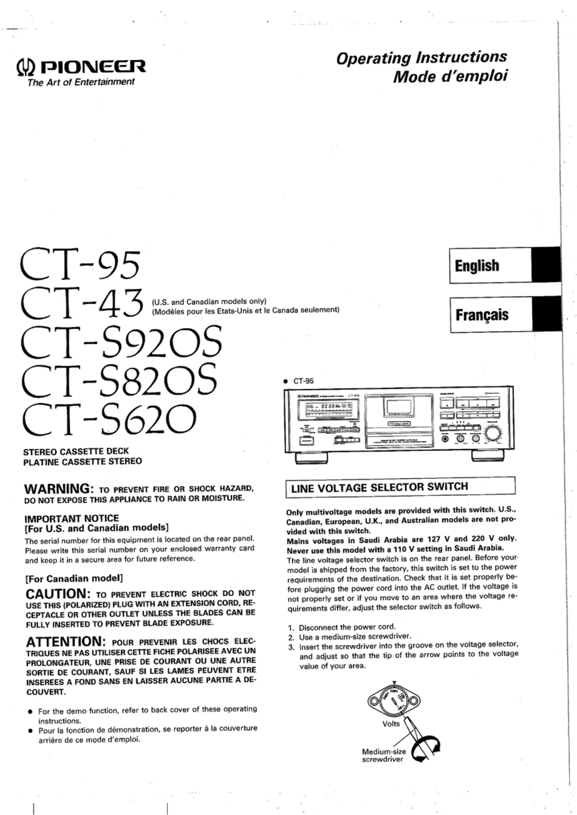
&
WOW
meter
47
kQ
LINE
OUT
Lor
R-CH
1.
Measure
the
output
frequency
and
the
WOW
value
while
playing
back
the
tape
top
of
the
test
tape.
2.
Turn
over
the
test
tape,
measure
the
output
frequency
and
the
WOW
value,
and
check
the
difference
from
the
values
of
the
step
1.
Adjustment
Limits
:
TAPE
SPEED
deviation:
within
2,990
to
3,010
Hz
within
2,990
to
3,010
Hz
0.04%
or
less
TAPE
SPEED
fluctuating
width:
WOW
(WRMS):
|
TC-K222ESG/K850ES
Playback
Level
Adjustment
Procedure:
Mode:
playback
test
tape
P-4-1300
(315
Hz,
0dB)
VTVM
jC
47
kK2
LINE
OUT
Adjust
RV101
(L-CH)
and
RV201
(R-CH)
to
ob-
tain
the
specified
LINE
OUT
level.
Adjustment
Limits
:
LINE
OUT
level:
0.41
to
0.46
V
(—5.5
to
—4.5
dB)
Level
difference
between
channels:
less
than
0.5
dB
Check
that
the
LINE
OUT
level
does
not
change
in
playback
mode
while
changing
the
mode
from
playback
to
stop
several
times.
PB
DOLBY
NR
Check
Procedure:
1.
Mode:
playback
test
tape
P-4-100
(10
kHz,
~10
dB)
47
kQ
—om
set
4
3
|
LINE
OUT
2.
Make
sure
that
the
output
levels
are
different
in
DOLBY
NR
OFF,
B,
and
C.
Adjustment
Limits
:
OFF
>B
level
difference
B
>C_
level
difference
-1
to
-3
dB
1
to
3
dB
Meter
Level
Check
1.
Apply
315
Hz
0.245V
(-10dB)
signal
to
LINE
IN
and
adjust
REC
VOL
so
that
LINE
OUT
level
is
0.4386V
(-5dB),
and
then
confirm
that
0
VU
segments
in
level
meter
light
or
flicker.
|
2.
Adjust
REC
VOL
to
obtain
2.19V
(9dB)
output
at
LINE
OUT
and
confirm
that
all
segments
in
level
meter
light
clearly.
TC-K222ESG/K850ES
MPX
FILTER
Check
Setting:
DOLBY
switch:
OFF
MPX
FILTER
switch:
OFF
Procedure
:
1.
Mode:
stop
AF
OSC
C)
attenuator
10
kX
x,
O
LINE
OUT
LINE
IN
.
315
Hz,
0.25
V
(—10
aB)
2.
Apply
315
Hz,
0.25
V
(—10
dB)
signal
and
adjust
REC
LEVEL
control
so
that
the
LINE
OUT
level
is
0.44
V
(—5
dB).
3.
Set
DOLBY
switch
to
B
or
C
and
MPX
FILTER
switch
ON.
Confirm
that
the
LINE
OUT
level
is
0.39V
to
0.49V
(-5dB
+
1dB).
4.
Apply
19kHz
0.25V
(-10dB)
signal
and
confirm
that
the
LINE
OUT
level
is
0.014V
(-35dB)
or
less.
Adjustment
Limits
:
LINE
OUT
level
315Hz
0.39V
—0.49V
(-5dB
+
1dB)
19kHz
0.014V
(-35dB)
Erase
Current
Adjustment
1.
Mode:
record
frequency
VTV:
M
Genhter
CNS65
yan
bce
i
|
|
3
o—_————2)
,
CEES
|
2.
Adjust
RV573
so
that
the
reading
on
VTVM
is
105mV
(erase
current=105mA).
3.
And
then
confirm
that
the
reading
on
the
frequency
counter
is
160kHz.
Adjustment
Limits
:
Erase
current:
105mA
to
110mA
Frequency:
160
+
6kHz
Bias
Current
Adjustment
Note:
This
adjustment
should
be
made
before
Record
Bias
Adjustment.
Setting
:
HX
PRO
switch:
ON
Procedure
:
1.
Preset
RV152
(L-CH),
RV252
(R-CH)
and
RV574
in
the
center
position,
and
record
with
no
signal.
2.
Adjust
T151
(L-CH)
and
T251
(R-CH)
for
minimum
readings
on
the
digital
voltmeter.
Adjustment
Limits
:
120mV
or
less.
digital
voltmeter
B+
(8.5V)
Record
Bias
and
Record
Level
Adjustment
Setting:
REC
LEVEL
knob:
standard
record
position
(See
page
10.)
HX
PRO
switch:
ON
Procedure:
1.
Mode:
simultaneous
REC/PB
LINE
IN
315Hz,
25mV
(-
30dB)
:
AF
OSC
10kHz,
25mV
(-30dB)
no-signal
tape
*)
10k2
CS-122
.
Oo
oO
LINE
OUT
2.
Adjust
RV153
(L-CH)
and
RV253
(R-CH)
so
that
the
playback
output
level
of
10kHz
signal
is
0.2dB
to
0.8dB
with
respect
to
that
of
315Hz.
*
¢
«Record
Bias
Adjustment.
3.
Adjust
RV151
(L-CH)
and
RV251
(R-CH)
so
that
the
playback
output
level
of
315Hz
is
-25.3dB
to
-24.7dB.
* *
*Record
Level
Adjustment.
(De.
Normal
Bias
Adjustment
Setting:
REC
LEVEL
knob:
standard
record
position
(See
page
10.)
Procedure:
1.
Mode:
simultaneous
REC/PB
LINE
IN
10
kHz,
25
mV
(-—30
dB)
AF
OSC
315
Hz,
25mV
(-30
dB}
no-signal
tape
6)
eke
CS-
122
0
o—o
o—o
LINE
OUT
2.
Adjust
RV152
(L-CH)
and
RV252
(R-CH)
so
that
the
output
level
of
10kHz
is
0.2dB
to
0.8dB
with
respect
to
that
of
315Hz.
HX
PRO
Operation
Check
Note:
This
check
should
be
done
after
Normal
Bias
Adjustment
in
the
same
connection.
Procedure
:
1.
Mode:
simultaneous
REC/PB
2.
Record
and
playback
10kHz
0.25V
(-10dB)
signal
in
both
modes
of
HX
PRO
ON
and
OFF.
3.
Confirm
that
the
playback
output
level
when
ON
is
1dB
or
more
with
respect
to
that
when
OFF.
|
TC-K222ESG/K850ES
Metal
Bias
Adjustment
Setting
:
REC
LEVEL
Knob:
standard
record
position
(See
page
10.)
Procedure
:
1.
Mode:
simultaneous
REC/PB
31SHz,
2SmVv(
—3008)
AF
OSC
10kHz,
25mV(
—30¢B)
no-
signal
tape
CS-
413
10kQ)
LINE
INPUT
LINE
OUTPUT
2.
Adjust
RV574
so
that
the
playback
output
level
of
10kHz
in
R-CH
is
0.2dB
to
0.8dB
with
respect
to
that
of
315Hz.
Calibration
Meter
Adjustment
Setting
:
CALIBRATION
switch:
ON
Procedure
:
1.
Mode:
stop
VTVM
no-signal
tape
CS-
122
8kHz
2.
Adjust
RV572
for
400Hz
and
RV571
for
8kHz
to
obtain
oscillation
level
within
10
+0.5dBs
respectively.
3.
Put
the
set
in
record
mode
and
adjust
RV131
(HIGH)
so
that
HIGH
FREQ
segments
in
the
CAL
LEVEL
meter
light
thoroughly
up
to
0
VU
as
shown
in
the
figure
below.
Segment
(a)
may
flicker.
4,
Preset
RV231
(LOW)
so
that
segment
(a)
in
LOW
FREQ
CAL
LEVEL
meter
lights.
Then
adjust
RV231
to
the
point
where
segment
(a)
goes
out.
HIGH
:
LEVEL
(a)
may
flicker.
+41GH
t
REC
CAL
FREQ
|
am
em oe
we
oe
oe
ee
om
on
LOW
we
one
oom
can
con
oon
Om
owe
ome
oD
ee
FREO
4
REC
EO
CAL
NORM
(a)
LOW:
LEVEL
(a)
must
not
flicker.
oe
TC-K222ESGK850ES
|
Rotation
Detect
Check
1.
Mode:
FF
or
REW
lewal
oe
IC1002
(take-up)
oa
1C1001
(supply)
2.
Waveform
on
the
oscilloscope
should
be
as
shown
below
a
b
a2
4.0V
bs1.0V
Adjustment
Parts
Location
:
RV101,
RV201
PB
LEVEL
ADJUSTMENT
CN802
TP
(TEST)
CNS64
RVI3I,
CAL
LEVEL
RV231
ADJUSTMENT
GAL
METER
ADJUSTMENT
RVS71,
RVS72
CAL
LEVEL
ADJUSTMENT
BIAS.
ADJUSTMENT
(METAL)
C805
6
RV1S2,
RV252
BIAS
ADJUSTMENT
(NORMAL)
LPFIS]
RV803
Ficaor|
TISt,
T251
ie
FWD
TORQUE
supply
BIAS
CURRENT
ADJUSTMENT
ADJUSTMENT
eee
RV153,
RV2S3
BIAS
ADJUSTMENT
1C5$2
|
16802
|
(HX
PRO)
|
icss2
CN80!
ROTATION
DETECTION
CHECK
CNS65
ERASE
CURRENT
ADJUSTMENT
ee
MAIN
(B)
BOARD
REC
LEVEL
ADJUSTMENT
-
COMPONENT
SIDE
—
RVS73
CNS62
CER
PRO)
ERASE
CURRENT
BIAS
CURRENT
ADJUSTMENT
ADJUSTMENT
MAIN
(A)
BOARD
—COMPONENT
SIDE
—
ee
TC-K222ESG/K850ES
SECTION
4
4-2.
SEMICONDUCTOR
LEAD
LAYOUTS
|
4-4.
iC
BLOCK
DIAGRAMS
DIAGRAMS
1C561
uPC1297CA
.
C803
BA62198
4-1.
BLOCK
DIAGRAM
BA6219B
2SD1761-EF
10E2N
IC804
LB1641
Lt
cathode.
L101
RVIO1
BIAS
TRAP
[PB_LEVEL
FLT901
49-52
——{_1°2+54°55
HRPSO1-1
een
1C504
OUTPUT
SELECT
JSS1-1
pe
Head
OF
a)
go
—
of
©
WH
1¢502
DOLBY
NR
RVSA1
|
PRE
ORIVE
MUTE
:
JS41
seese
tel
ae
F
F
anode
C841
@exeicten)
|
Ey
+—
Puane
HE
ADPHONE
9
OFF
; ;
9501
102
ne
SAV
Re
oxeeoeee
Q90S,
906
a901-904
aio!
CALIBRATION
CAL
METER
j
@i3t
ON
908
a909
GAIN
AMP
EQ@
SWITCH
OFF
/B/C
Qso2
SWITCH
MUTE QS03
LENE
MUTE
METER
SW
COUNTER
SW
—_—_—-4
MODE
7
INVERTER
RVi31,
RV231
FWO/REV/STOP
ee
LB1641
2SD2144S
Pane
Leete
RVSSI
$821
30DF2
BALANCE]
(CD
DIRECT)
(5)
CAL
METER
(7
;
pe
J551-3
OFF
Tass
LPFISI
|
$S22-2
0
O-—-b
4
(OLBY_NAl
!
:
ON
INPUT
@
'
Q910-92)
cathode
LINE
IN
©)
{
vr
|
OFF
'
°
DISPLAY
1C502
552
CX20188
LINE
IN)
BUFFER
Wrricie
f
’
©)
()
(8)
(7)
JSSI-2
&
cel
I
romeo
=
>
HRPSO!-2
B
40e
48
CONTROL
y
=
nae
sine
=e
:
a
is
%
ae oi
(CL
DIRECT
(C583
REC
HEAD
sate,
a
2
z
a
ae
3
=
=
-
a
ag gs
_
po
on
a
‘coal.
>
we
2
ou
oz
RVSS3
RVISi
EE
ee
AMG
a
INDICATOR
CONTROL
=
x901
12345678910
=
ae
=
aS
ats
2
8
=
=
>
z=
36
pe
ET
B+
$521-6
REC
LEVEL)
gio
eo
hg
CAL
METER
8523-2-2
0
peneeo-y
enode
Ss
ye
w
ive)
4
aie
5
pad
@521
|
AMS
DET
MOTE
RYN
52
Hx_PRO
|
e
Go
&
3
1C801,
IC902A
TC4069UBP
CD
DIRECT
0526
151,
QS51
BIAS
OFF
toad
susie
seeneee
69
64
sahil
SWITCH
)
CALIBRATION
552
$523-2-1
A
Leeeeend
NERRUL
STG
PX
FILTER
DIRECT
Seiten
REG
MULE
;
Ml
i
0523
$522-1
a
2SK246-GR
OFF
DOLBY
OFF
DOLBY
NR
=
SEL1210S
Ps
S|
SWITCH
aiss
7ais3
Tass
ON
@15é|
ABSO
1C902A
GP1U52XB
ON
|
ee
TP
(CHECK)
SEL1210S$-C
i
He
ic909
Dae
itee
SEL1910A-C
Q524
°
:
SWITCH
COMPARATOR
9801
REC
MODE
c
IBS
ad
SWITCH
Detect
o
Yorse
*
:
:
i
SG
b
Le
=
IC902B
CX20174
$1006
=
>|
CALIBRATION
-
eee
oe
Nes
de
4c
menos
id
|
Raa
@) @)
©
o-
g
(HALF)
1562
aiicd
BIAS
_
g
Ue
x
re
Zz
22:
Floto
44
fs
sis
9802
CALIBRATION
OSC
@152-Q155
y__
HeSot
te
2
=
eo:
52,
32
22
Se
z
-
TYPE
W
6)
Ci)
EQ
SWITCH
ber.
@561,
562
ERASE
HEAD
$901
eunegs
=
3
on
acu
RS
zr
re
a
x
=
8
8
‘
iocg
%
9
q
4
ehane
cp
ae
eS
|
Fal
ice
ne
CURRENT
Peete
(RESET)
HZS6C3L
enode
8
2
@-2-63-0)
(METAL)
(Bee
aia
@571,
$72
hati
.
U2ZL-12H1
&
,
ea
a
eee
|
oe
|
2
(8)
qoonn
acer
ON
BIAS
if
9922,
a923
DTA114ES
UZP8.2BB
/CURRENT
Rie
rena
tan
ee
SWITCH
RVS73
[ERASE
CURRENT
2
MOTOR
DTB114ES
1$S202-1
CONVERTER
SuaGHiie
eee
,
Beat
DTC114ES
VOLTAGE
VOLTAGE
pa
area
DTCT44ES
.
/CURRENT
/CURRENT
5
-
NVER
or
Pet
cre
ttt
TEBIquee
sagide
4-3.
CIRCUIT
BOARDS
LOCATION
|
CONVERTER
FL
:
=
|
‘
VOLTAG
1701
|
say
BIAS
Ae
28A1317-
STU
MAIN
(C)
BOARD
(CONVERTER
ji
0566
SELECT
D601-604
2S8C2458-
YGR
7
e362
601,
602
;
COMPARATOR
BOARD
AMS
1C804
M1002
'
Aselet
Bt
+7V
603.
605
L
BIAS
ASSIST
MOTOR
DRIVE
hci
REG.
enode
CAPSTAN
BOARD
oa
eae
:
Prarie
we
MAIN
(B)
BOARD
Bt
HALE
SWITCHING
3
REEL
MOTOR
BOARD
iaMiear
9807
9804-806
eG
GP2S22B
MONITOR
SW
LINE MUTE
0606-609
%
2)
$1002
D00R)
“>
~
suewerre
inlnen
1C803
M1001
B-
-7V
a
y
REEL
:
3q
b2
E
$1003(CLOSE)
~0~-
STATE
DETECT
MUTE
REEL
MOTOR
MOTOR
,
MD
BOARD
MAIN
(A)
BOARD
°
8
@|
(Tp
siooutorew
om
Oe
Se
|
PANEL
(G)
BOARD
;
51005
wp)
oe
ee
l
cone
Ee
eee
C952
TC9142P
2
REEL
ROTATION
~~
B-
-22V
<——
AON
Ae
28C945-
P
4—4—
1
(3)
-
DETECT
3
REG.
2S8C1815-Y
$1001
Oo
$<
<2
ae
44
|
=
ROTARY
rr
1C805
|
ENCODER
o-
|
SYSTEM
‘i
z
A
=
eohange
47)
COUNTER
OFF
RVB03_
Bt
+12V
vee
‘
$903-914
<1
REG:
CN701
SS
~
48)
METER
OFF
:
D703-706
OHO009
4
>=
epee
Leto
TIMING
eee
_
OA
CON
1C1001
1C801
os
;
AC
IN
PANEL
(F)
FG
BOARD
VERTER
S$
REEL
(1/6) (2/6)
eo
voeeeeeeeeeee-
CAPSTAN
MOTOR
:
a703
y
Fc,
Lean
F
BIT)
aie
ROTATION
SHAPER
KEY
MATRIX
D903-905
3
Bt
v6
BOARD
DETECT
acre
=
i
:
SWITCHING
.
we
NH
Bt
+5V
t
i
Tc802
RESET
:
OUT(
+)
srewae
(3/4)
4)
Bt
+9V
eae
T
REEL
SHAPER
i
'
REG.
VH
ROTATION
cNao!
Q812
1c801
:
i
So
6
VC
OUT(-~)
~
Sica
ieapest
vecbees
See
eee
ero
|
INC
DETECT
INVERTER
vw
(5/6)
he
Bt
ee
hen
2SA985A
(-)
PANEL
(c)
BOARD
2
a
=o
DET.
T6902
ars
aes
|
w/e
28C2275A
PANEL
(B)
BOARD
3
REMOTE
‘
a
707,
708
~
AFC
ena
4
1C902B
MOTOR
DRIVE
Bt
+5V
a
:
Rg
ae
RECEIVER
POWER-OFF
heneerat
|}
va
con
DETECT
|
ate
t
:
PANEL
(A)
BOARD
S80!
E
(TIMER
ne
é
PANEL
(D)
BOARD
REC
~~
OFF
—*PLAY
$701
|
PANEL
(E)
BOARD
POWER
OFF
—~
ON
2245
=
—16—
=e
19
—=
TC-K222ESG,/K850ES
4-5.
PRINTED
WIRING
BOARDS
—
MAIN
SECTION
—
*
Semiconductor
Location
|
|
9
5
|
66
\7
Ig
|
\9
|
20
2
22
Co
24
|
25
26
30
3|
|
32
fil
EE
Fe
Na
[aston
Ft
Ne:
[Lanter
Ro
Wa,
[Leoter
:
1541
1C551
A
1C552
10553
1561
10562
1C801
1¢802
B
[CAPSTAN
BOARD]
1803
1804
1805
1C9028
10951
1C952
1C1001
1C1002
T70!
POWER
TRANSFORMER
EXCEPT
E
MODEL
E
MODEL
{MAIN(C)
BOARD}
US,CANADIAN,
MODELS
TO
CHASSIS
Q101
Q102
Q131
Q132
Q161
Q152
Q153
Q154
TO
PANEL{A)
BOARD
vS90l
VOLTAGE
SELCTOR
120V
{
240V
L
220v
{PANEL(C)
BOARD)
RSOT
‘ft
ANE
L(G)
BOARD
Q155
-
}
(PANEL(G)
]
7
ee
aa
0202
-
0231
-
Q232
-
mn
|
1
a
0-10
|}
9252
>:
9
984
-
[COMPARATOR
BOARD]
D-14
|}
0255
-
id
}
ier
:
TO
PANEL
(A)BOARD
H-12
|}
Q502
-
H-12
|}
0503
-
ae
,
G-10
||
9504
-
wp
O1(
OO
H-13
Q523
~
TO
PANEL(A)
BOARD
errr
ey
yy
HM
eee
ay
H-13
PE
|
7
Q524
Q525
Q526
Q551
Q552
Q561
Q562
TO
PANEL
(A)
BOARD
t
KO
RO
RO
AD
AO
AD
—
A
—
RIAD
AD AD
DD
DAD
PY
A
PY
DY
A
AY
HO
NDI
NPD
DY
DY
HD
PS
DMM
WWhIW
OO
DWOPW
PNW
WWWW
OF
HSH
WNWWhRWwWworec—-
:
rs
Ye
i
meee
eC
Hg
Ge?
{
RO RO
no
>
*
S100!
ROTARY
ENCORDER
aa
ON
!
E
0
E
E
H
H
H
G
G
G
B
C
c
G
I
I
[-
I
ie
I
B
F
F
E
J
J
G
E
G
G
J
J
{MD
BOARD]
{
PANEL(B)
BOARD}
)
[PANEL
(e)
Ssh
t
BOARD
eer
err
Tes
reeerr
ed)
UCNMERSEE
Le
Te
HRPSO}
Note
on
Mounting
Diagram:
REC/PB
HEAD
HESO!
®
O——:
parts
extracted
from
the
component
side.
pea
“1541
HEADPHONES
$1001
¥
ROTARY
ENCODER
TO
PANEL(A}
BOARD
12~14,
22,23
Iw
14
<7
—
14>
—20—
—21—
—22—
aR.
|
—24—
TC-K222ESG/K850ES
4-6.
SCHEMATIC
DIAGRAM
—
MAIN
SECTION
—
1
2
3
4
5
6
7
8
9
10
11
“12
13
14
15
16
17—
18
19
20
21
22
23
24 25
26
27 28
29 30
31
TO
MAIN
(A}
BOARD
=
SSS
-
z
FY
MAIN
(A)
Icsor|
ic502
eB)
[
BOARD
en
R29
¢220
ie
RC
4558P
Q504
2SAI3I7
|
'
as
Ne
:
(Re
DoLeY
AMP
:
FILTER
AMP
uaa
ek
$
!
HRP5OI
(1/23
5
|
|
p38
une
cured
Soo
eemuas
D502
cnso2
|CNS70
(pa,
HEADPHONE
(MAIN(B)
BOARD]
*
ts
C80
C80!
=
=
PB
HEAD
see
0.
Se
ane
18mH
Gy)
REC
IN.
GAL
1¢
502
METER
MUTING
ISSI33
L
ofl
10K
em
@)
(3/6)
(4/6
SE
ERECREE
Q804-807
D802
ee
=
ae
5
aa
‘
ciel
¢
<<
o
5
aig
DTAI4ES
=i
220
TT
Sa
®
a
n
eee
eT
rn
=
Piel
TaD
BORROTT2N
0
ain
o/50V.1
cos
|
clog
heel
gp
0
5
|
Ow
—%
HEADPHONES
7 -
SOP
ae
:
(NON-POART
o.027
|
38P
sera
Em
shoved
eal
220
|
|
o
4
weal!
GP2S228
rca
G
[og
10K
Be
TOO
“ToONN
ars
y
1cgo2(3/4)
””
1¢802(4/4)
(3P)
6P25228
g
=
2K
“T
0.0018
To.0018
8
a
2
fs
cae
ae
ve
+
cial
nies
.
_]
CN806.I0P)
|_|
fo
1
Ga
i954
1
Il001
doe
Bek
Sy
787
{RCH
vo}
[Tee
Rae
OOS
ee
ee
aa
ee
oon]
R802
220K
4
foe
oe
il
:
|
oft
Ali
ee
!
pein
ca
;
gins
(FG
BOARD]
150
i
Re
147
|!
rexjoee\cusl
SR
.
”
To
PANEL
{A}
LED
SWITCHING
J
FG
COIL
00
Collector
24K
RI38
RI40
180
10K
|
z
RC4558P
*
es
Se
en
z
age
|,,
ERE
e-
lo
Q202
0
MUTING
RI34
0
CNS521
(2/2)
:
|
G3)
3)
DI3!
ics01
Qlol
2SD2I44s)
S01
2sD2144s
rooiz
|
reo2e
Sn53z
\o/sov
RI
aoe
aan
\
ee,
PB EQ
SWITCH
CAL
SWITCH
10K
a7k 22k
a
sieg
UJ
(NON-POLAR)
F47K
ms
Al
ol
es
Q132
el
eon
M50964-220SP
'
Q502
DTCII4ES
me
Ea
UP
a)
pos
|e
|
2,
ASTER
r
cza
CN9SI(2P)
SWITCHING
:
HC131
+2
:
ai
:
we
RSI4
a7K
:
RI37
DI3I,
0231
T33/50V
Q8i4
Q80!-803
iC802
|
[Sole
ARATOR]
‘LBiov
cane
oe
cs
S.
pee:
(ar
hs
cae
ree
Le
=
ee
ap
als
|
-
\cos|
MANMEe
mec
NyM4580D-D
@/2)
TOK
/|
Cy
REEL
MOTOR
aaa
120K
os
REC
EQ
AMP
RV555_5K
cl67
86
a
|
IC804
|
KBOARD
—8
46
a
cr
fies
Das
DOLBY
AMP
(r)
Wan
aie
®
t
LBI64!
C1053
0.1
Se
eu
57
ROSSB
48
|
po57
RVISI
\
O
R238
R240
ASIST
MOTOR
aS\
.
47
IK
C169
ri7a\iox_[
]
a!
Lt
y+
Pha
023!
|80
tok
J551-|
+345
16X78)
(9110)
S31
lL
JyGls
10K
HRPSO!
(2/2
crn
Ms
ae
10/50V
6.8K
aaa
pee
")
Ress
R150
SL"
518
(mw)
M002
Jal
7
R9538/
b
+{C953
Cy
* 7
rs
lens7a
tox
|
974
=
IK
LINE
ey)
feo]
MoroR
=
[SS
120K
=
100
4
ED
i.
aint
—
‘|
cee
=
tT
i
C806
.
°
or,
25V
L-CH
“=
i
RI80
G6)
ave
ean
QI3!
2SD2144S
—-
TOSHIELOING
(ouTPUT,
10K
0.1
He
C178
4.7K
0
irs
LINE
MUTING
PATTERN
m0
[lac
|
tas
[ci0si
torsov
:
180P
39K
Riz
0231
2
—_
US,
Canadian
1C803
:
:
a
€550
—
S.¢
in
Ea
RI78
56K
“
3.3K
_
>
|
Collector
(R-CH)
Q503
DTCi44ES
Sop
a
MODELS
mk.
BAG62I9B
O O
aay
ci68
oT
6 0
MONITOR
SWITCHING
—
©
Py
6
|
REEL
MOTOR
DRIVE
(wm)
Mio
a-cH
el
ci66
a7)
Boy
_°85
WO/5OV
Bex
[eANe.
(Cl
[bONEL
ID)
]
ve
Q816
2SAI3I7
ae
{062
[OI
nen
agoa
0.
;
i)
28!
BOARD
4
ABOARD(1/3)
!
|
ta
9808
2SAl3i7
sree
oaNtes
cl68E
Tars0v
0
e
(Op
07
QS
as
ae
of
ic
IK
-
07
~
Chev)
Tons!
Rist
J551~2
1SS132
:
|
MOTOR
CONTROL
a
5
_|
Rios!
390
S
Nad]
|
aise
esoziea
lovesv
JES]
7260
oF
18S)
G5,
|
sbi
a7
se
=r
Ho]
y—@
SS
ee
|
ne
ee
er
2
eee
aes
Gee
||
Pete
ia
as
fea
LP.
2
=
0812
DTAIIAES
i
me
06i6
ae
22k
aes
a
sk
|
RRR
SWITCHING
x
5
ps
Saar
ORES
eS,
om
“77
rd
|
72
>
CD
DIRECT]
4
Wa:
Q8i2
ee
ed
LR
casseTTe
L]_
!
neh
=|
OFF
R640
33K
it)
9
|
|
[ow
i
rT]
|
|
[|
0806
resa7k
264)
Ax
RBI
SRI
LAMP
Ist
ai,
deg
cngo2
F
=
;
:
r)
3
10k
9.1K
(SLF~325¢)
rtd
maar
a
Ts)
a
1)
3
amet
Lea)
88
ro
:
RV803
<
eS
ee
ee
ORNAMENTAL
PL.
CH
isms
reac
peso
|
(aa
need
(eae
oe
95)
Re6
470
i
a
a
:
a
|
J
-D
:
Ba
Di
A
cee
Q551
DTAII4es
IC562
d_
UT
eure
it
Led
a
eer
Lt
|
ae
sama
Note
on
Schematic
Diagram
.
QI53~155
HO
eae
Reraror
wee
4
dso
RV552-1
=
INPUT
>
2
ee
eae
ce
"
D805
,
D806
ISSI32
|
PS
Alle
ccomets
seamen
Eta
|
$1002
(DOOR)
®
All
capacitors
are
in
wF
unless
otherwise
noted.
pF:
wuF
$
CALIBRATOR
x
=
7 . .
:
ne
£0
SELECT
©
Ge?
:
EAN
!
oa
oe
L
_
||
aon
ee
50WV
or
less
are
not
indicated
except
for
electrolytics
Riss
areas
off...
|B
:
x6
t
o—
|
toes
S
Bana
a
+}
et
Fy
sioot
id
e
All
resistors
are
in
2
and
1/,W
or
less
unless
otherwise
REE
OK
3
Lt
ovsse_
ge
ho
;
+:
ft
i
eee
OI
ENRODER
specified.
B+
RIS4
Bal
:
a
+
|
ce
“a
shine
~
i.
=
NEE
TC
a
@
Components
for
right
channel
have
same
values
as
for
left
a
a
R565
4.7K
:
=
as
=
\
Bote
338
[eias]
%
CH
r,
6
[PANEL(A)BOARD(2/3)]
sig
pol
Pir
iag
[MD
BOARD
(2/2)]
channel,
Reference
numbers
are
coded
from
201
to
299.
2.2mH
:
f
<
-
Bt
°
4:
internal
component.
i
(Ar)
-e7
{
PANEL(A)
BOARD(3/3)]
sate
Peeenes
eNbesti/2!
aes
eo
erkene
ant
r7o!
+L¢701
0702
oe
:
:
C56!
cw)
i
Ro]
z|
OFF
O
4.7K
47/50V
>
J.
ospl
lig
(tol
Be
°
feed
:
nonflammable
resistor.
1
}
>
0
5
+
0
ra)
F i
CN562
PCI297CA
g
j
tal
{
-08S>
C702.
~25
REG
@
{~~}:
fusible
resistor.
PI
BRO
nos
|
Ste
(Sp.
aor]
0568
ON
'
To
PANEL
(A)
|
100/50V
QI56_DTCII4ES
+O,
572
Q603
2SK246
ps
ate
: :
sii
ces
ea
chet
kHz]
BOARD
(2
}
e-
carve
R914
[RIB
Note:
. 5
Note:
P
se
”
ee
é
[satz]
BOARD
(2/3)
D605
HZS6C3L
D606
1SSI32
an
cone
«|_|
=
0S
08
The
components
identi-
|
Les
composants
identifies
par
108
-88
5K
Lips7!
ea
oe
or
>
!
CAPSTAN
MOTOR
“GaK
g
fre.
6906
“
iiss
bY
Heat
of
dots
une
meraue
7
sont
critiques
ml
O
. ;
=
Q809
m
‘1
DRIVE
S
II6V
C307
|C909)
te
ine
with
mar
pour
ta
securite.
[BIAS]
R574
[DOLBY
NR]
ae
coop
ter
ils
HESO!
>
es
QTCHaES
(CALIBRATION)
Zh
CTT
(BouBY
ne]
7
=
s
OTCIIES.
5/8
i
es
aaa
are
critical
for
safety.
Ne
les
remplacer
que
par
une
ee.
“4% “84
Und)
0870
eqn
“
.
Pe
Ae
+
|
DETECTOR
4}
|
th
ead
joriey
Replace
only
with
part
|
piéce
portant
le
numéro
spéci-
0561
9,
Slices
08
|
ars
©
a6o1}
"°°
|
a6o3
5
Iggit
a6!
D60!
a
135
50y
iE
bee
ae
number
specified.
fié.
°
oR
S
pay
-~
82K
1
47K
R569
.
Ror?
ee
§|
3
+
0608,
e
98
¢i
15
Pa
Als
0602
Cy)
2
-88
CURREN
4.3K
:
22000
Fes
q
2,
$
wy,
T701
(2/2)
D707
3
Pe.
B+
Li
rys74s]
35V
S22
602
R6OI
A
D701
-
706
J
B
+
+
ine
aE
‘Potion
dese
Pas
eg
Lee
=]
=|
|g
2608
:
+h
css
i
(OE2N
ERASE
047/50V
-8.8
(rs
Yee
0604
Q610
3300
IL
t
I
@
:
B-
Line
CURRENT
tL
c563
6.8K
(Ay) (Ap)
-88
D526
9:
0
25V
D7IS
HZSI26
D707
!
lo/50v
ay,
~88
ely,
“87
ISS132
D522
$523-2-1
1
Part)
6.4
hot
(A
Q610
nee
'
!
T701
(1/2)
HZS6C3L
:
agen
ee
Ste
See
eee
71
:
:
‘
320
OOH
¢
Wn
DT
CIES
1
|]
4
‘power
e
:
adjustment
for
repair
28
88
azo
etl
ime
520,522
DTAII4ES
ts
foorov
#0605
#0606
DELAY
SW
SiGe
hy
eas
D708
1SSI32
CALIBRATE
SWITCHING
OFF.
FORMER
D709
l0E2N
'
Voltage
and
waveforms
are
dc
with
respect
to
ground
++
+
R530
47K
CN522
(~™3]
NOSI7
H
Q60I
2SC2275
ba
pigs
(
!
d
ignal
(det
d)
diti
2s
‘
o
,
<
vsooi
A
ne
nditions.
.
;
Q525
DTAII4ES
aus
sw
524
oTcii4es
U4
”
1)
qo?
—_
REGULATOR
SS
iDIane
yt
D7i2—714
ISSi32
under
no
signal
(detuned)
co
Q561,562
2SC945
Q570
2SCI8I5
Q565,
566,
567
Q526
DTCII4ES
cal
sw
CAL
SW
DET
Se
59.9
5
Q602
28D2144S
POWER
SWITCHING
I
=
CNP701
no
mark:
STOP
osc
REGULATOR
DTCII4ES
,
A)
REGULATOR
Lees
D708
1
TeEXCEPT
E
MODEL
“Er
A
|
-
PLAY
BIAS
SEL
SW
Lt
R608
pa
0605
2SC2458
Reg
oa
ds
iPore
eo
7
Acie
ues
):
PL
[C561
PIN
®-®
REC
B=
|
D563~D566_
ISSI32
AMS
eee
rah
“94
cS
REGULATOR
2
Q705
2SC2458
.
E
!
«
»:
REC
=
=
35V
REGULATOR
=
!
CNP70!
j
i
Ww]
park
Weades
0568569
DTCIa4ES
a
I
|
nsor
(ok
0604
DTCIM4ES
rs00
)\
ae
a
|
ie
Rata
e@
Voltages
are
taken
with
a
VOM
(Input
impedance
10
MQ)
Q572
DTCI44ES
CALIBRATOR
SWITCHING
C0609
&
i
yyy
Sol
|
:
'
I
Voltage
variations
may
be
noted
due
to
normal
produc-
BIAS
SEL
SWITCHING
>
=
2
ribs
pw
ey
3s
z
,
fe
=
oh.
2
Ilk
|
,
.
;
<
12
>
Q609
250985
Q608
2SAI409
Q606
2SAI3I7
Q607
2SK246
12
|
J
EIS
cat
f
Q707
2$C2458
708
2SDI76!
~b-;------
see
EES
COPEL
PUE
Dita
ae
i
HOT
AQ
Ier
ees:
13
SPECULATORS
D60i~604
ozo}
bed
LO
Sod
D7H
=UZP8.2BB
REGULATOR
REGULATOR
en7orp
&
:
@
Signal
path.
mS
=
os
_
500F
2
;
J!
2
3.4
5
de
dr
ds
le
REC
~
OFF
—
PLAY
OFF
~
ON
a
:
>
PB
a
a
,
Nt
a
es)
:
Cle
TO
MAIN
(B)
BOARD
|
BOARD BOARD
y>>
:
REC
TO
PANEL(A)
OD
Sis
5
—26—
ee
eee
|
ye
—29—
TC-K222ESG/K850ES
4-7.
PRINTED
WIRING
BOARDS
—
PANEL
SECTION
—
Ref.
No.
|
Location
D141
:
D521
-
0803
:
eM
een
TO
MAIN
(B)
BOARD
TO
MAIN(B)
BOARD
TO
MAIN
(A)
BOARD
0901
:
i
2
ry
0902
D903
D904
0905
D906
0907
0908
D909
0910
[PANEL
(A)
BOARD]
tincLUDING
PANEL
(B)-(G)
BOARD)
Cr
Tt
fo
f_1_WHT
4
a
a
ee
RELI
0913
2
=
}
RRR
a
aI
a”
/
>
sete
Reece
een
eee
eee
aR
SSSR
Se
ae
Soe
EE
See
ee
Se
EE
eee
cr
WO
WONDMWOOOODOL
NON
—~
WOOO
Mm
D915
RR
ERS
Ic901
ICS02A
1C903
TC904
CEES
AA
EN
Ore
Soe
CoO
Mm
&
w
Q520
Q521
Q522
Q901
Q902
Q303
Q904
Q905
Q906
Q907
Q908
Q909
Q910
Q911
Q912
Q913
Qg14
Q915
Q916
Q917
Q918
Q919
Q920
Q921
Q922
Q923
sf
PRIOR
t
MOH
WWD
WO
WOMMW
MO
OOO
MWN
HHH
WOM
WO
Soe
Seer
t
i
a
oo
oe
eee
wie
a
!
C
C
C
D
D
D
D
E
E
C
E
E
E-
E
E
E
E
D
E
D
D
D
D
D
C
C
Se
a
esp
teat
sotearey
=
a
a
a
oe
a
ae
Note
on
Mounting
Diagram:
®
O——:
parts
extracted
from
the
component
side.
—30—
—31—
|
_32—
4-8.
SCHEMATIC
DIAGRAM
—
PANEL
SECTION
—
2
1
3
FLT901
$3
dB
HIGH
/
=20
FLUORESCENT
LIGHT
INDICATOR
TUBE
ee
-3x0
Lo
oeSses
1G
=|
-4
0
+2
+4
+8
10
+8
+10
le)
c
d
e
f
g
h
i
j
;
k
!
m
n
°
p
q
r
$
t
u v
Ww
x
SE
eS
SS
SS
ae
ee
eg
eg
chy
11
$521-5
|
OFF
R
Bee
ge ge
a
ag
a
re
ee
a
ee
f
c
e
i
j
ON
3
|
<<]
DIRECTION
o>
OOM
|
ca
=
s9
REC
CAL
NORMAL
.
Cro02
ME
TAL
CO
DIRECT
DOLBY
NR
BC
MPX
FILTER
HX
PRO
“SOURCE
TAPE
$523-I-I
Q915-Q917
DOI!
MPX
FILTER
DTAII4ES
1S$132
SWITCHING
En
TOF
¢
;
G8)
v7
=
ON
7)
oul
¥
DOLBY:5.0
9
35
38
39
40
41
42
43
44.45
46
47
48
49 50
51
53
R956
!
erie
eo
oon
SOSDODODDDODDNDONNS
$522-2
D9I5
Q916
<12)4
al
DOLBY
NR
ISS13|2
T
Raney
ce
zs
-
El
fd
3
:
Lens
Q901-
0904
|
é
ooleyne
=
es:
8
|
3
a9
Se
DTAII4ES
t
1g
7
3
8
ae
5
COUNTER
SEG.
5.0
8
6
sy
a|
3
=
SWITCHING
Am,
Es
$523-2-2
—¢
lelululx<|x
2
<I
x
2
x]
x]
x
slo
|
3)8/8/s/8/8]3/8)
5
8}
8/3]
8/88
aa
FoF
fg
eal
ooo
_f=lglele|=|elal3|s
s|
=|3|
313)
aon
'$
=
ae
ae
3/2
12/3)
212]
8
2
2|
2/2]
38/2
ii
1]
fo
{1
fe
5,0
(3
4)
2
L
4
=
2
2
—
bl
yey
2
=
3
ia
;
1
-20
nite
_[
Ho
<18>
=
a
=.
TB
|
Q905
9906
me
|_|
en
OTB
IES
=
ON
Q918,Q920
919,092!
AE
k
est0,a911
I
SWITCHING
DTAII4ES
—DTCII4ES
2
Q9l4
oe
'
ee
{9
SWITCHING
-
SWITCHING
96
1a
ie
if
eAtaLd
y
-24
1Q908.0909
=
Q910
Fxon:96
_
tea
ne
ee
ee
a
|
son
¥
otal)
4g
ETE)
Bo
‘ren
coaes
|
METER/COU!
@-—!
J
0913
ws
:
2°
pgog
2913
Mig
ON:
OFF
30
31
32
33
34
35
36
37
36
%
40
a1
42
43
44
4
46
63
54
55
56
1c.904
seine
aig
eee
ae
al
8)
WYER
SERIES
BBE.
|
[syya
of
3/38/33
38
GPIU52xB
954A
7
(t)
Isst32
©
co
ai
4
retin
RECEIVER
5
Sa
I$$132
oh
nae
*
OOS
98
hot)
aves)
1...
@
zy
Q914
ISS132
Sposen
\
56
50
3
LE,
WICH
")
ag
3
|
:
i
us
e
Qo
ban
5.0
Q909
"°°
MONITOR
Q92
Q912
,Q913
le
||
OTCII4ES
F
SWITCHING
Rael
MAIN
(B)
l2Vv
BOARD
CAL
SW
°
eZ
oe
5V
me
zl
4+
i
No
815
4
|
METER
OFF
i
|
COUNTER
OFF
—-
+
RESET
M_MUTE
R924 R923
B
¢
MEMORY
he
20K
20K
C
RESET
1
19
gL
—%6
>
D141,D241
T
ax
)
?
'
cS)
BOARD”
=
—5>
Gel
a
LH
—_——£55
-56
ISS132
]
OKT
ae
|
MR
=fed
54
83
5.0
ux
Y
014]
024!
QO
Nosi4
ly
R942
R943
R944
R945
|
;
C
R4g
=
2.7K
3.9K
8.2K
27k
6)
abe
ee
>
Hpi)
ale.
Ag
Bs
ae
ead
|
$903
$904
fb
fear
$906
b
$907
Q923
145.0
6)
1C903
eB
aoe
me
ee
ob
7
@
kek)
Be
LM2903P
£3
Bx
e@-—
R946
27K
—-
R947
3.9K
R948
8.2K
R949
27K
5,0m4
0.1
alta
@)
naman.
3
am
10
“I
=e
BI
sig
]
$912
Q922
0923
boa
Y
$902
3
’
50
ened
BOARD
|
F
$908
[E
5909
[sete
eee
pee
DTCI44ES
0
eae
ae
id
[>]
at
Ml
¢
[eq]
OL
pi]
i
(]
0.1
INVERTER
®
ae
:
D903
|p905
ae
ey
$
a92
~o—
=B5
No
0904
D904
le]
By
M9
D/A
BUFFER
2S
813
ee
om
K
a
1905
pig
bn
S913
$914
$901
R937
’
SEL
IzI68
SELI4IOE
o|
PUBPLEH
«
-
Fao
|
x
=
“
Kat
48
%
[ise
ero—_
Q907
ws
8
|
@-
He
DTCII4ES
e
No8i6
SWITCHING
TO
MAIN(
A}
BOARD
=93..
12
—34—
Note
on
Schematic
Diagram:
All
capacitors
are
in
wF
unless
otherwise
noted.
pF:
wuF
50WV
or
less
are
not
indicated
except
for
electrolytics
and
tantalums.
All
resistors
are
in
Q
and
1/,W
or
fess
unless
otherwise
specified.
A:
internal
component.
|
B+E
B+
Line
|
B-§
B—
Line
.
|
ae
adjustment
for
repair
Voltages
are
taken
with
a
VOM
(input
impedance
10
MQ)
Voltage
variations
may
be
noted
due
to
normal
produc-
tion
tolerances.
TC-K222ESG/K850ES
SECTION
5
EXPLODED
VIEWS
NOTE:
@
The
mechanical
parts
with
no
reference
@
Due
to
standardization,
parts
with
part
The
components
identified
by
number
in
the
exploded
views
are
not
number
suffix
-XX
and
-X
may
be
dif-
mark
or
dotted
line
with
mark
supplied.
ferent
from
the
parts
specified
in
the
Avare
critical
for
safety.
components
used
on
the
set.
eplace
only
with
part
number
@
The
construction
parts
of
an
assembled
part
are
indicated
with
a
collation
num-
®
Color
Indication
of
Appearance
Parts
specified.
ber
in
the
remark
column.
Example:
Les
com
i
ifié
posants
identifiés
par
une
e
|tems
marked
“*"
are
not
stocked
since
(RED)
...KNOB,
BALANCE
(WHITE)
marque
A
sont
critiques
pour
la
they
are
seldom
required
for
routine
t
t
sécurité,
service.
Some
delay
should
be
antici-
Cabinet's
Color
Parts’
Color
Ne
les
remplacer
que
par
une
pated
when
ordering
these
items.
piéce
portant
le
numéro
spécifé.
5-1.
OVERALL
SECTION
WG,
K850ES
:
E
MODELS
ee
ote mre
ee
eee
oereh
meen
ee
ee
905
=
o
eos
E
MODELS
=
>
11
OO.
~
WG
MODEL
Al
OO
LP
LO.
~~
US,CND
MODELS
oe
ie
9
SP
><
UK
MODEL
oS
<
Ss
wo
rs
a”
y
“
B
oe
9
“ae
CNP701
<
s
MODELS
USCND
~~
24
MODELS
i
4
8
03
Pr
supplied~__/
;
Wine
>
t
.
supplied
|
not
sp
“A
'
,
7
FS
co
14
not
supplied
EXCEPT
E
MODELS
EXCEPT
Ker"
K85OES
:
E
MODELS
6
EXCEPT
WG,
E
MODELS
850ES
:
E
MODELS
.
not
supplied
901
(including
MIA,
B
OOK
not
supplied
:
}
RS
7
Abbrebiation
:
CND:
Canadian
WG:
West
Germany
een
eae
|
19
2
:
;
a
cata
WG,
K850ES
:
E
MODELS
|
oe
SS
1
a
b—3
:
1
No.
Part
No.
Description
Remarks
No.
Part
No.
Description
Remarks
1
7-682-548-04
SCREW
+BVTT
3X8
(S)
20
4-933-446-01
(WG,K850ES:E)...SCREW
(SIDE
PANEL)
2
X-3304-944-1
FOOT
ASSY
2]
3+701-947-12
(WG,UK)...LABEL
(T1.25A),
FUSE
3
3-703-685-21
SCREW
(+BY
3X8)
22
7-685-133-19
(E)....SCREW
+BTP
2.6X6
TYPE2
N-S
4
7-682-547-09
SCREW
+BVTT
3X6
(S)
23
3-356-961-01
(E)....COVER
(TRANSFORMER)
5
4-925-039-41
CASE
24
3-703-044-26
(US,Canadian)..
.LABEL
,
CAUTION
6
3-704-366-01
SCREW
(CASE) (M3x8)
25
*4+352-844-01
PIN,
LEAD,
COATING
7
=*4-912-962-01
(EXCEPT
£)...COVER
(1P),
TERMINAL
26
X-3304-971-1
(WG,K850ES:E)...PANEL
(L)
ASSY,
SIDE
8
%*3+703-244-00
(EXCEPT
E)...BUSHING
(2104),
CORD
901
*A-2006-174-A
(WG,UK,E).......
MOUNTED
PCB,
MAIN
3-703-571-11
(E).......
BUSHING
(S)(4516),
CORD
*A-2006-276-A
(US,Canadian)...MOUNTED
PCB,
MAIN
9
3-831-441-XX
CUSHION
(B),
CABINET
903
1
-533-213-31
HOLDER,
FUSE
10
7-621-849-00
SCREW,
TAPPING
905
A1-526-565-00
(E)...AC
PLUG
ADAPTOR
11
*3-350-460-11
(US,Canadian)...PANEL,
BACK
CNP7OVA1
-551-188-XX
(E).
ccc
eee
eeeee
CORD,
POWER
*3=350-460-21
(UK).........66-
PANEL,
BACK
CNP701A
-555-465-00
(US,Canadian)...CORD,
POWER
*3-350-460-31
(WG)............
PANEL,
BACK
CNP7OIA
=555-795-00
(WG)...
ccc
eeeees
CORD,
POWER
*3-350-460-61
(K222ESG).......
PANEL,
BACK
CNP7O0IN1
-556-035-00
(UK).
....ecceeee
CORD,
POWER
*3-350-460-71
(K850ES:E)......
PANEL,
BACK
F701
A\1-532-285-00
(WG,UK,E)....FUSE,
TIME-LAG
(1.250A)
12
=*3-657-780-00
(EXCEPT
US)...CUSHION
F701
A1-532-741-11
(US,Canadian)....FUSE,
GLASS
TUBE
(1
.25A)
13
7-682-547-04
SCREW
+BVTT
3X6
(S)
14
7-682-548-09
SCREW
+BVTT
3X8
(S)
T701
AV-449-985-11
(US,Canadian)...
TRANSFORMER,
POWER
15
4-902-345-01
HEAT
SINK
T701
A1V-449-986-11
(WG,UK).........
TRANSFORMER,
POWER
T7017
A1-450-065-11
(E).
ec
cee
cee
eee
TRANSFORMER,
POWER
16
7-682-147-15
SCREW,
TR
17
4-870-539-00
PLATE,
GROUND
VS701
Al-570-307-11
(E)....SWITCH,
VOLTAGE
CHANGE
18
3-350-459-01
ABSORBENT
(S),
VIBRATION
19
X+3304-972-1
(WG,K850ES:E)...PANEL
(R)
ASSY,
SIDE
—35—

This manual suits for next models

2

Other Sony Cassette Player manuals

Sony TC-TX373 User manual

Sony

Sony TC-TX373 User manual

Sony Walkman WM-GX100 User manual

Sony

Sony Walkman WM-GX100 User manual

Sony CFS-515L User manual

Sony

Sony CFS-515L User manual

Sony Walkman WM-GX221 User manual

Sony

Sony Walkman WM-GX221 User manual

Sony TC-W421 User manual

Sony

Sony TC-W421 User manual

Sony TC-KA6ES User manual

Sony

Sony TC-KA6ES User manual

Sony TC-RX77 User manual

Sony

Sony TC-RX77 User manual

Sony Walkman WM-EX552 User manual

Sony

Sony Walkman WM-EX552 User manual

Sony CFD-S36 - Cd Radio Cassette-corder User manual

Sony

Sony CFD-S36 - Cd Radio Cassette-corder User manual

Sony WM-EX668 User manual

Sony

Sony WM-EX668 User manual

Sony Walkman WM-EX674 User manual

Sony

Sony Walkman WM-EX674 User manual

Sony CFS-E2 Operating Instructions  (primary... User manual

Sony

Sony CFS-E2 Operating Instructions (primary... User manual

Sony Walkman WM-FX700 User manual

Sony

Sony Walkman WM-FX700 User manual

Sony WM-AF65 User manual

Sony

Sony WM-AF65 User manual

Sony Walkman WM-FX675 User manual

Sony

Sony Walkman WM-FX675 User manual

Sony WM-EX190 - Walkman Cassette Player User manual

Sony

Sony WM-EX190 - Walkman Cassette Player User manual

Sony CFS-B7SMK2 User manual

Sony

Sony CFS-B7SMK2 User manual

Sony TCM-R3 User manual

Sony

Sony TCM-R3 User manual

Sony Walkman WM-FS566 User manual

Sony

Sony Walkman WM-FS566 User manual

Sony Walkman WM-FX491 User manual

Sony

Sony Walkman WM-FX491 User manual

Sony TCM-20DV - Mini Cassette Recorder User manual

Sony

Sony TCM-20DV - Mini Cassette Recorder User manual

Sony Walkman WM-FX665 User manual

Sony

Sony Walkman WM-FX665 User manual

Sony Walkman WM-EX2000 User manual

Sony

Sony Walkman WM-EX2000 User manual

Sony TC-WR465 User manual

Sony

Sony TC-WR465 User manual

Popular Cassette Player manuals by other brands

Silvercrest SKD 1000 A3 user manual

Silvercrest

Silvercrest SKD 1000 A3 user manual

Panasonic RQ-SX53 operating instructions

Panasonic

Panasonic RQ-SX53 operating instructions

Sharp QT-CD7L Operation manual

Sharp

Sharp QT-CD7L Operation manual

Aiwa HS-PX590 Service manual

Aiwa

Aiwa HS-PX590 Service manual

Philips AQ 6688/11 Instrucciones de manejo

Philips

Philips AQ 6688/11 Instrucciones de manejo

Philips D7180 operating instructions

Philips

Philips D7180 operating instructions

Panasonic RQ-SX32 operating instructions

Panasonic

Panasonic RQ-SX32 operating instructions

Jensen SCR-68A operating instructions

Jensen

Jensen SCR-68A operating instructions

Yamaha MT120 Operation manual

Yamaha

Yamaha MT120 Operation manual

Aiwa HS-PX590AH Service manual

Aiwa

Aiwa HS-PX590AH Service manual

Aiwa HS-JXM2000D Service manual

Aiwa

Aiwa HS-JXM2000D Service manual

Yamaha KX-E300 Service manual

Yamaha

Yamaha KX-E300 Service manual

Yamaha K-09 owner's manual

Yamaha

Yamaha K-09 owner's manual

Sanyo MCD-Z250F Service manual

Sanyo

Sanyo MCD-Z250F Service manual

Becker 755 manual

Becker

Becker 755 manual

Aiwa HS-TA203YL Service manual

Aiwa

Aiwa HS-TA203YL Service manual

Philips D 7476 operating instructions

Philips

Philips D 7476 operating instructions

Pioneer CT-W404R Service manual

Pioneer

Pioneer CT-W404R Service manual

manuals.online logo
manuals.online logoBrands
  • About & Mission
  • Contact us
  • Privacy Policy
  • Terms and Conditions

Copyright 2025 Manuals.Online. All Rights Reserved.