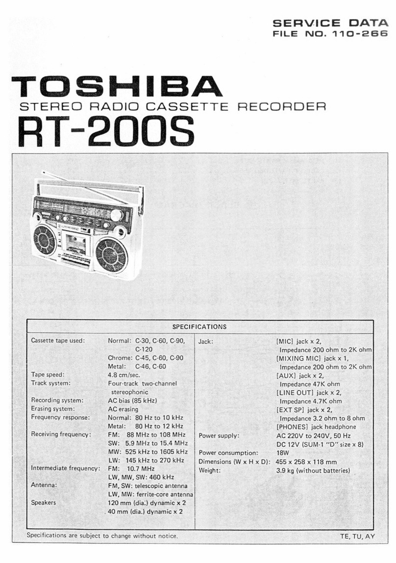
Toshiba RT-S933 User manual

SERVICE
DATA
FILE
NO.
110-279
TOSHIE
ioe
RADIO
CASSETTE
RECORDER

{T-S933
|
CONTENTS
1.
OPERATING
CONTROLS
.......
0...
ee
es
3
to
4
2.
DISASSEMBLY
INSTRUCTIONS
........0
2.0.2
0
ee
ee
eee
5
to
6
3.
MOTOR
PULLEY
REPLACEMENT..........
0.2
20
e
eee
ee
7
4.
HANDLE
REMOVAL...
2...
0...
ee
7
5.
DIALCORD
RESTRINGING
...
20.0.0...
ee
eee
7
6.
BLOCK
DIAGRAM...
0...
cc
ee
ee
eee
ee
8
7.
ADJUSTMENTS
INSTRUCTIONS.
........0.0.
0000
ee
ee
ee
ee
9
to
12
8.
SCHEMATIC
DIAGRAM
..........
00.
ee
ee
13
9.
ELECTRICAL
PARTS
LOCATIONS
(MAIN)...
2.0.0.
.00
02
ee
eee
ee
ee
14
10.
ELECTRICAL
PARTS
LOCATIONS
(CONTROLS)
..........
0-0-2
eee
eee
ees
15
11-1.
EXPLODED
VIEW
(CABINET)...
2.0.0...
ee
ee
ee
16
11-2.
EXPLODED
VIEW
(CABINET)
PARTS
LIST.
2.0...
2.
0
eee
ee
ee
17
12-1.
EXPLODED
VIEW
MECHANISM
(UPPER)...
2...
..0.-
22
ee
ee
ee
18
12-2.
EXPLODED
VIEW
MECHANICAL
(LOWER)
..
2...
2...
eee
ee
19
12-3.
PARTS
LIST
(MECHANISM)
..
0.0.0...
00
eee
ee
ee
eee
ee
20
13:
(PARTS
LUST:
2.006.
f4
Ge,
bbe
PRE
ge
Dh
a
oe
pee
aS
ee
ah
i
ap
Sl
g
Fe
ee
ee
21
to
28
i
POWER
SUPPLY
|
m=
Batteries
(optional)
Open
the
battery
cover,
insert
9
dry
cells
(SUM-1
“D”
size),
observing
correct
polari-
AC
POWER
AC
POWER
|
ty
(+,
—)
indication.
™
To
Check
the
Condition
of
the
Batteries
When
the
set
is
turned
on,
the
[BATTRY]
indicator
7
should
light
up.
If
it
fails
to
light,
the
batteries
have
run
down,
and
all
9
batteries
must
be
replaced
with
fresh
SUM-1
“’D”
size
batteries.
=
AC
POWER
This
unit
operates
on
either
household
current
of
110-127V
AC.
The
[AC
POWER]
socket
46
located
on
the
side
of
the
set
is
pre-set
at
220-240V
AC.
Connect
one
end
of
the
power
cord
to
[AC
POWER]
socket
46
and
the
other
end
to
an
AC
outlet.
Precautions
on
power
source
changeover
Prior
to
changing
over
the
[AC
POWER]
socket
46,
confirm
the
local
voltage
of
the
current
to
which
this
cassette
recorder
is
to
be
connected.
Should
it
be
inadvertently
connected
to
the
wrong
voltage,
trouble
may
result.
To
operate
the
set
on
110-127V
AC
Slide
the
cover
of
the
[AC
POWER]
socket
46,
and
connect
one
end
of
the
power
cordto
[AC
POWER]
socket
46
and-other
end
to
an
AC
outlet.
POWER
CORD
(i
ia

|
ar-s933
RT-S933
|
1.
OPERATING
CONTROLS
©
@
Tuning
knob
©
[FINE
TUNING]
Control
©
[RADIO]
Selector:
FM/MW/SW,
/SW,
OQ
[FUNCTION]
Selector:
TAPE/AUX/PHONO/RADIO
@
[TUNING]
Indicator
@
[FM
STEREO]
Indicator
@
[BATTERY]
Indicator
©
[TAPE
SELECTOR]
Selector:
NORMAL/CrO,/
(We)
©
[VOLUME]
Control
@
TREBLE
Control
@
Bass
Control
@
[BALANCE]
Control
©
[MODE/BEAT]
Selector:
MONO/STEREO/SPACE
WIDE
©
Level
Meters
©
[MIC]
Jack
os
WIRELESS
Figure
1
©
[PHONES]
Jack
@
Infrared
Sensor
Window
®
Built-in
Microphones
©
Tweeter
Speakers
@
MQJS/TIME
COUNT
EDITOR/AUTO
REPEAT
Indicators
@
(TIMER/MQJS]
Button:
OMR/TIMER
OFF
—
©
WO
/TIMER
ON
®
[AUTO
REPEAT]
Buttons:
m
/
1
€
[vVOPEN]
Button
@
Tape
Transport
Mode
Indicators
@
Woofer
Speakers
&
[=STOP]
Button
@
[eRECORD]
Button
@
[<««REW/REVIEW]
Button
@
[»PLAY]
Button
@
[>>
FF/CUE]
Button
Figure
3
@
[1IPAUSE/ED!TOR]
Button
@
[VOLUME]
Buttons:
UP/DOWN
&
[MQJS]
(AUTO
REPEAT)
Buttons:
SET/RESET
&
Remote
Control
Button
Indicator
€&
Tape
Counter/Counter
Reset
Button
€&
[TIMER]
Switch:
m=
RECORD/(1PB
&
[POWER]
Switch:
ON—LILOFF/SLEEP
Note:
In
the
(1
OFF/SLEEP
position
the
mains
power
will
still
be
supplied.
Therefore,
when
not
in
use
unplug
the
cord
from
the
socket.
@
[SPEAKER]
Jacks
@
Telescopic
Antennas
@
[LINE
OUT]
Jacks
@
[AUX/PHONO]
Jacks
@
[MIC]
Jacks
®
External
FM
Antenna
Terminal
@
(PHONO
-4,]
Terminal
@®
Batteries
Compartment
@
[AC
POWER]
Socket

2.
DISASSEMBLY
INSTRUCTIONS
=
FRONT
CABINET
REMOVAL
1.
Remove
six
knobs
(A)
from
the
front
of
cabinet.
(Figure
4)
2.
Remove
seven
screws
(3¢
x
35
mm)
from
the
rear
of
cabinet.
(Figure
5)
Open
the
Cassette
Lid
by
pressing
the
open
button.
3.
Remove
the
connectors
from
the
speaker
terminals
and
the
front
cabinet.
=
MECHANISM
ASSEMBLY
REMOVAL
1.
Remove
six
screws
©)
(3¢
x
35
mm),
©
(3¢
x
12
mm)
and
©)
(3¢
x
8
mm).
(Figure
6)
2.
Remove
three
connectors
from
the
P.C.
Board
and
the
mechanism
assembly
can
be
removed.
=
POWER
P.C.
BOARD
REMOVAL
1.
Remove
four
screws
()
(4g
x
12
mm)
and
the
power
P.C.
Board
can
be
removed
from
the
back
cabinet.
(Figure
6).
BID
Tapping
Screw
©
3@
x
12
mm
(Red)
BID
Tapping
Screw
©)
4¢
x
12mm
y
Figure
6
Figure
4
Figure
5
wy
|
RT-S933
RT-S933
|
»
Wi
LEss
BID
Tapping
Screw
3¢
x
35
mm
(Black)
“3
BID
Tapping
Screw
3¢
x
35
mm
(Red)
BID
Tapping
Screw
3
x
12
mm
(Red)
=
MAIN,
CONTROL
AND
TONE
P.C.
BOARDS
REMOVAL
1.
Remove
one
screw
(€).
(Figure
6)
2.
Remove
two
screws
@
(3¢
x
12
mm)
and
pull
out
the
P.C.
Boards
frontward.
(Figure
6)
=
CONTROL
P.C.
BOARD
REMOVAL
1.
Remove
four
screws
)
(3@
x
6mm),
and
restore
two
hooks
(U),
and
disconnect
the
two
connectors.
(Figure
7)
2.
Separate
the
control
P.C.
Board
from
the
Main
P.C.
Board.
@
TONE
P.C.
BOARD
REMOVAL
1,
Removal
two
screws
(1)
(3¢
x
6
mm)
and
the
tone
P.C.
Board
can
be
removed.
(Figure
8)
=
REMOTE
CONTROL
RECEIVER
P.C.
BOARD
REMOVAL
1.
Remove
two
screws
G)
(36
x
10
mm).
(Figure
8)
2.
Remove
the
screw
©)
(3¢
x
35
mm)
to
detach
the
mounting
bracket
for
the
infrared
receiving
P.C.
Board
from
the
mechanism
assembly.
3.
Furthermore,
remove
the
connector
from
the
control
P.C.
Board,
and
the
remote
control
receiv-
er
P.C.
Board
can
be
removed.
=
REMOTE
CONTROL
TRANSMITTER
REPAIRING
1.
Remove
the
remote
control
transmitter
from
the
unit.
2.
Push
the
function
buttons
and
confirm
the
trans-
mitter
operates
correctly.
3.
When
repairing
the
P.C.
Board,
proceed
repairing
after
removing
two
screws
)
(2.66
x
8
mm)
to
detach
the
rear
cover
of
the
transmitter.
(Figure
9)
|
WIRELESS
FEATHER
TOUCH
LOGIC
CONTROLLED
SYSTEM
RM-933
ay
)
DT
BID
Screw
36x
6
mm
Figure
7
®
F
DT
BID
Screw
3¢
x
6
mm
©
BID
Tapping
Screw
=
T
PAN
Screw
(Washer)
3¢
x
35
mm
(Red)
3¢
x
10
mm
Figure
8
BID
Tapping
Screw
2.6
x
8
mm,
Chrome

6.
BLOCK
DIAGRAM
RT-S933
RT-S933
3.
MOTOR
PULLEY
REPLACEMENT
=
MOTOR
PULLEY
INSTALLATION
O
©
»
|
OIW
GWV
XIW
ONIXIN
NoISSauddNS___Z£8O
BRON
SIN
S
lOv
‘ON:
(>
Ovo
saoine
@)
s1v8
Y¥aMOd
eziiose
2H
nop
p34
la
LINDEID
3dVi
o—®
IW
O
@
AB
40193130
MOLOSTIS
“OS
.
YaNNI
a
ee
mpd
O
CC)
|
2/1
av
@
-8ze2v1
Py
|
Paw
34d
‘MS
4V37
d3a7s
90e0N
20€0
4
4A/0-ASG9Z9S2
S060
‘a
WV
Y3MOd
OIW
“LX3
ano,
‘dW
_ss3nano7
MO7
*
3WMI0A
—
HOIH
ONOHd
NI
"LX3
WV
Y3aMOd
qaqa
NOliva3dO
QV3H
AW1d/934,
TOYXLNOD
SWN10A
NOY19373
da6v0vo1L
£vso
QV3H
asvaa
aS1Nd YaWIL
dZElZvi
YOL93130
osv
av3H
RY
Avid/938
30!S
¥30I1S
avayH
@
ONOHd
2
©)
Ni
CLX3
Yi
3LNW
>
%
Ke
ee
o__loeo
DIW
“xa
MS
NOLLONAS
SO
eo)
xs
|
BMLS
HSNd
id9992¥1
£090
BAING
Y3L3W
40193735
"03
TOSLNOD
YyOLOW
133a
ouvmuos
il
Nol
say)
YANNI
O—©)
ino
ann
dv029rdo1
SI8O0
NdW
3SH3A3u4
ww
“MS
p
NOISS3dd
Sc
3
hae
y*
Q
&
yoioaas
anva
“MS
Sen
900718
an
C)
1D5,x
(Z
Te
i
YOL0373S
GNVE
bs,
TON
LNOD
7HA08b
214
ha
o
5
aiona
10S
0
Na
a
SMS:
ag
ms
!9%.X
ah
aais
asnvd
CA
ROHE
ash
sre
ZHIOSY
40193130
1020
P
zms
zing
1109
9sO
S001S
Ig
uggooad
XdW
&)
mS
aber
aes
“mS
YOLD37aS
NvE
.
‘ani
o3uais
wi
@)
W/W
@-=J
40103735
'
~®)
onva
£OLSdL
x
dVbI9ZVL
dSEeLvL
samad
°
1010
1000
\00z
W4
Q37
NOlLwa3d0
My
dW
4
zo10
(M4)
BAIsG
031\S
(on!
oninns
Nv
D
c
cc
Q
yn
£
:
~
itd
vt
o
-
ew
ES
()
a
ts
ae}
ao
2
5548
=
=
=
i)
c
>
2
5
2@ses
=
5
+
Ld
ro)
i=)
LL
°
ue
ro)
=
fe)
oO
—_
a
)
a
cy
iL
2
ro
=
Co
»
9
2
=e
oe
£
>
cc
6
2
5
se
=
=
S24
‘
$s
o
ei
a
mM
eo
§&
22
+
ie
-
CC
=
2
®
mOsm
on
+
pea
|
>
.
TD
(e)
&
2
TC
=D
oS
a
+e
o
3
o
2
6d
xo
oi
brart
2
SUS
8
£
i
*
5422
=
=
4”
ne
=
ce
35
oOo
o
ore
@
€
<=
=
~
P
ee
°
+’
Ss
QE
=
B26
ol
©
@)
Oe
ais
aE
qaQexy
tl
eee
x
“=
0
€
=
yy
O
YO
E
of
oe
2
i
=
fe
oi
Ee
+3
<£Z%oce
@
of
63
A
of
~Y~
2
5
@
ay
Os
Be
ra
@
6
N
5
9
Mw
#>
oc
o
2
v
=
as
oo
FD
=£o
£229
2
pans
of
2°:
PL
p
OC
o
2
=
=
Oo
a
et
oo™~
>
os
Ios
Sls
2Oo
2¢€
xv
uw
od
ie
we
Ee
HANDLE
REMOVAL
4.
DIAL
CORD
RESTRINGING
5.
Turn
the
drum
counterclockwise
Never
apply
a
drop
of
adhesive
on
the
part
(A)
ra
fe)
Pa)
°
E
o
x=
ra)
Ras
ee
°
Pe)
~~
°
Cc
drum
shown
in
Figure
14.
2.
Wind
the
dial
cord
in
numerical
order
shown
in
n
c
_
Ss
Fk
2
oe)
Figure
12.
we
2s
05
2
0
DH
Cc
=
om
£
s
o
&
=
TD
Cae
sf
£@
o
+4
oe
oF
oD
2
oO
3
@
me
o
ee
o
=
2
“6
o
gf
=
0
2
»
ace
°
FS
.
@
=
3°
ag
2
ne)
c
i]
c=
C0)
x=
ra)
@
>
°
E
c)
_
°
Pw)
When
installing
the
pulley
to
the
motor,
keep
the
clearance
(2
mm)
as
shown
below.
Apply
a
little
adhesive,
LOCKTITE
601
(Code
No.
22
964
085)
into
the
head
of
the
pulley
to
fix
the
pulley
with
the
motor.
Note
1.
Thread
the
dial
cord
through
the
hole
of
the
=
HANDLE HOLDER
REPLACEMENT
Note:
Wind
the
cord
on
the
tuning
shaft
with
care
not
=
DIAL
CORD
RESTRINGING
Figure
15
on
the
drum.
Figure
14
Figure
12
to
turn
the
unit
over.

|
RT-S933
RT-S933
|
7.
ADJUSTMENTS
INSTRUCTIONS
MW
ALIGNMENT
CHART
Signal
Generator
Radio
Dial
Setting
Adjustment
Frequency
Tuning
Gang
Fully
Counter-
455
kHz
clockwise
(Lowest
Frequency)
Adjust
for
maximum
indication.
fe)
TP-|
FREE
RUN
Tuning
Gang
Fully
Counter-
510
kHz
clockwise
(Lowest
Frequency)
Adjust
for
maximum
indication.
T108
Tuning
Gang
Fully
clockwise
Adjust
for
maximum
(Highest
Frequency)
indication.
1650
kHz
wl
Osc,
x
aes
SW2
OSC.
T1OS6
epeat
steps
2
and
3
as
required.
Cle3_
Clee
See
Ant.
Coil
Adjust
for
maximum
TI07
AM
IF
AMIF
600
kHz
|
Tune
to
Signal.
LOO6
De
eas
TI04
TIO3
sid
[e]ésé
FM
IF
.
Ant.
Trim.
Adjust
for
maximum
LOO4
SWI
.
1400
kHz
Tune
to
Signal.
C022
indication:
Repeat
steps
5
and
6
as
required.
C124
mwosc,
_-002
TIOl
Loos
"REM
le
SW2
ANT.
osc.
coo4
ANT.
COlIB
av
FM
OSC.
sw
1
(Oe)
SW
ALIGNMENT
CHART
sy
LOOI
Signal
ANT.
C020
MMC
ANE
FM
ANT.
R202
Generator
Radio
Dial
Setting
Adjustment
SW2
ANT.
Frequency
LOO6
et
iil
GROUND
FM
IN
Tuning
Gang
Fully
Counter-
2.25
MHz
clockwise
(Lowest
Frequency)
OSC.
Coil
Adjust
for
maximum
T106
indication.
Tuning
Gang
Fully
Clockwise
OSC.
Trim.
Adjust
for
maximum
7.7
MHz
(Highest
Frequency)
C122
indication.
Repeat
steps
1
and
2
as
required.
Figure
16
|
aes
Saree
.
red
Ant.
Coil
Adjust
for
maximum
3
MHz
Tune
to
Signal.
L004
faaicatiod:
TEST
EQUIPMENT
:
Ant.
Trim.
Adjust
for
maximum
7
MHz
Tune
to
Signal.
C018
aGiention,
1.
Signal
generator
with
a
frequency
range
of
at
least
from
455
kHz
to
23
MHz
AM.
;
2.
Oscilloscope
with
a
wide
range
amplifier
of
approximately
100
kHz.
Repeat
steps
4
and
5
as
required.
3.
Test
loop
—
a
coil
of
any
size
wire,
one
turn
or
more.
(MW)
Turina
Gana
Fully
Counter:
;
4.
A
30-ohm
dummy
antenna.
(SW1,
SW2)
7.35
MHz
clockwise
Adjust
for
maximum
5.
VTVM.
(Lowest
Frequency)
indication.
AM
ALIGNMENT
|
Tuning
Gang
Fully
Clockwise
Adjust
tor
masitodin
eee
(Highest
Frequency)
indication.
1.
Turn
on
the
AM
signal
generator
and
the
VTVM
allowing
a
fifteen-minute
warm-up
period.
Repeat
steps
1
and
2
as
required.
2.
Using
the
test
loop
across
the
output
of
the
signal
generator,
inductively
connect
the
signal
generator
to
the
_|
:
radio.
‘
9
MHz
Tune
to
Signal.
Ant.
Coil
Adjust
for
maximum
3.
Connect
the
VTVM
across
the
voice
coil
or
a
3.2
ohm
dummy
load.”
LOOS
indication.
4.
Set
signal
generator
frequency
as
listed
in
ALIGNMENT
CHART
and
maintain
a
sufficient
output
level
to
provide
;
‘
.
an
indication
on
VTVM.
20
MHz
Tune
to
Signal.
eee
apa
on
5.
Set
volume
control
at
mid-position.
6.
Proceed
as
outlined
in
the
IF-MW,
SW1
and
SW2
ALIGNMENT
CHART.
Repeat
steps
4
and
5
as
required.

|
RT-S933
RT-S933
|
FM-IF
ALIGNMENT
FM-RF
ALIGNMENT
1.
Set
the
select
switch
to
FM
position.
1.
Turn
on
the
signal
generator
and
the
VTVM,
and
allow
a
fifteen-minute
warm-up
period.
2.
Turn
on
both
sweep
generator
and
oscilloscope,
and
allow
a
fifteen-minute
warm-up
period.
2.
Connect
the
signal
generator
output
through
a
75
ohm
dummy
antenna
across
FM
ANT.
3.
Connect
the
RF
SWEEP
SIGNAL
OUTPUT
from
the
signal
generator
through
the
loop
antenna
to
the
receiver.
3.
Connect
the
VTVM
across
the
voice
coil
or
a
3.2
ohm
dummy
load.
4.
Connect
the
oscilloscope
vertical
input
directly
to
the
test
point
TP-2
FM
and
connect
the
shielded
lead
to
the
4.
Set
the
volume
control
to
mid-position.
GND.
5.
Adjust
the
signal
generator
frequency
as
indicated
in
FM-RF
ALIGNMENT
CHART,
and
maintain
a
sufficient
5.
Connect
the
SWEEP
VOLTAGE
OUTPUT
of
the
sweep
generator
to
the
oscilloscope.
signal
output
level
to
provide
a
measurable
indication.
6.
Proceed
as
outlined
in
the
FM-IF
ALIGNMENT
CHART.
6.
Proceed
as
outlined
in
the
FM-RF
ALIGNMENT
CHART.
FM-IF
ALIGNMENT
CHART
FM-RF
ALIGNMENT
CHART
Signal
Generator
Radio
Dial
Setting
Adjust.
point
Pattern
Signal
coupling
Connection
Tuning
Knob
fully
87.3
MHz
|
Counterclockwise
(Lowest
Frequency)
Adjust
for
maximum
Set
scope
for
con-
Turn
the
coil
L105
fully
aut
indication
Sweep
necting
output
counterclockwise
to
obtain
Connect
sweep
BREratORGE
Tuning
Knob
|
signal
from
TUN
a
single
peak.
Fig.
19.
generator
output
to
a0
7
MHz
fully
counter-
|
OUT
to
vertical
Adjust
coil
L101
in
order
a
three-turn
loop
i
clockwise
axis
of
scope
““V""
until
the
best
single
peak
antenna
of
10cm
(Lowest
and
sweep
gener-
is
obtained.
diameter.
Frequency.)
ator
output
to
Finally
turn
the
coil
L105
horizontal
axis
to
obtain
S
curve.
“HT
See
Figure
20.
Tuning
Knob
fully
109
MHz
Clockwise
(Highest
Frequency)
Adjust
for
maximum
output
indication
center
freq.
with
10.7
MHz
marker.
Repeat
steps
1
and
2
as
required.
90
MHz
Ant.
Coil
L001
Adjust
for
maximum
Tune
to
signal
output
indication
106
MHz
Ant.
Trim.
IF
Sweep
Test
c003
FM
Sweep
Generator
Receiver
under
test
Repeat
steps
4
and
5
as
required.
eae
amavis
4
ae
ee
4
a
of
—WA—
F_
0a
To
signal
generat
To
signal
130~
330hm
~~:
10pF
swt
~
SW2)
Sc
greeo
cent
TOsreceiver
generator
ITo
receiver
a
:
h
(SG
imp.
50
ohm)
(SG
imp.
50
ohm)
|
:
E
ot
———___________lo
3-turn
Loop
Antenna
located
near
the
L001
or
LOO2.
ee
i)
ee
ee
7
E
Figure
17
75
ohm
dummy
antenna
30
ohm
dummy
antenna
Generator
Coupling
Hook-up
Figure
21
Figure
22
FREE
RUN
FREQUENCY
ALIGNMENT
Adjust
R202
under
no
signal
condition
so
as
to
obtain
38
kHz
+75
Hz.
°
Ant.
Term.
Receiver
RECORD/PLAYBACK
HEAD
ADJUSTMENT
under
test
A
6.3
kHz
standard
tape
must
be
used
for
this
adjustment.
Connect
a
VTVM
or
an
oscilloscope
Tape
(A)
Tape
(B)
(C)
to
the
EXT
Speaker
jack
and
adjust
the
azimuth
Figure
18
by
using
a
philips
screwdriver
to
maintain
the
R/P
maximum
output
voltage.
Head
SCUIVE
Caution
in
R/P
Head
Replacement
(Figure
23)
7)
Losseness
of
the
R/P
head
mounting
hole
and
=
screw
may
cause
clearance
between
the
head
R/P
Head
Adjusting
and
tape
as
shown
in
figure
(A).
In
this
case,
Screw
Push
MOJS
function
does
not
operate
correctly.
x
C)
Xx
Therefore,
adjust
and
fasten
the
screw
by
pushing
the
R/P
head
in
the
arrow
direction
as
shown
in
figure
(B).
Do
not
proceed
to
adjsut
Figure
23
the
head
as
shown
in
figure
(C).
Figure
19
Figure
20
—11—
-—12—

|
RT-S933.——s-RT-S933__
——
ae
oe
oe
ee
8
gio
—ANNy
; : ; - : : : :
———
:
fe
Tae
ok
|
a
os
ae
2
ee
pie
fea
fee
O22
ee
: :
ee
é
aoe
r :
me
R202
ae
;
i
o.02
2]
22K
:
IO!
:
i
(PDT
10KB
:
130
os
|
So
12K
fb
cl22
Swi
¥
|
ces
7
Ss
<A}
eS
|
ROCs
io}
RES
tt
AAS
SWik
at
Teoee
ee
em
ee
“12k
ot
:
0.022
_
5322.
i
THOT
1eo25
|p
2h
clez
0.022
ts3
.
Ci24
5384
co02
Tape.
fOrhers
|
es
OV.
LOO6---2913
MW.
ee
Ngee
eae
ee
-
.
oo
:
ele
sr/so
LS)
|
22
a
:
Lo
Q
9805,0306
eo
=
|
o.ayso
ea
Ras
; : i
a
Lee
Ean
|pa3e
‘
C
he
oes
a
:
022
Tisov
|
ee
Ge
vt
|
=
oc
—_—
al
ee
-
ol
LS
a
Cee
[ieee
ee
a
Ser
a
a
S
*
=
ives
“ 3
‘5
‘I ze ne
ae
x : “
5:
e S &
2
#
ees
z a 2 2
‘.
Va 53
vi
ty
c308
; :
——
:
6
=.
|
313
|
4700
a
mae
22M
ae
é ;
a
|
19480
)
39K
:
dea
OE
: é eo
eee
A
- -
js
i
isee
ae
: :
:
4
:
504
cd
A
lesig.
: i
ae
ok
; : -
eens
é
So
:
:
:
Others
: :
Radio,
EXT
Phono,
Tape.
Q60!,
G602
GS
MIXING
MIC
||
JACK
Rec:
eee
an
B.0V|
Others
}HEAD
PHONE.
13.
“
66V]
Rec
JACK
as
<<
6,2V]
Others
:
ee
OuE
Eee
PBV
Ree:
»
eed
“ONE
Others
os
cee
Others
G.7Ni
Rec.
pjHOOS
oe
Muting
“SAV|
Gihers.
é
oe
bs
:
OD
i
eee
4
ae
3
EE
=
=
ae
Ss
: Z
pee
i
‘ : 3 i 2 : :
ee
Ree:
Muting1-5V)
REC/PB
Ap
Ee
OREO
(eS
:
pete
:
ce
:
sean
a
ee)
Sees
WE
Rea
ob
:
gs
Aee
|
lpeee
by
:
:
"OV
1R306
10K.
ae
Jooa
oe
:
Q505,506
Gore
g8e4
TC40498
Re7s
REC/PSI
Rich.
“TATI37P
TAT335P
_
‘TAT343
“TA7205A0P
Bae
ase
bee
=
=
:
20
123)
:
Pes
|
Bee
iar
C
ee
re
TC40I6BP

[
RT-S933
RT-S933
|
9.
ELECTRICAL
PARTS
LOCATIONS
(MAIN)
From
Meter
i
i
P.€.Board
|
To
Control
From
Meter
{OV
j0.08V
6.
:
4
;
a
:
!
feel
P.C.
Board
P.c.Board
I
10.
:
|
i
[B)
i
[
MODE
/
BEAT
|
[Mic
|
[PHONES
|
—
STEREOS
es
a
(swe
(Swi
(Swi
(Mw)
|MwibWi|[eM
||
[RADIO
|
(PHONO
|
[aux]
[TAPE]
|
METAL
|
|
|
;
|
[MONO
|
|wIDE
|
i
5
i
geo,
|
|
\To
Control
|
:
|
PC.
Board
|
J
{
|
|
|
|
|
i)
|
|
|
{
|
|
|
|
|
\
}
|
i
i
ee
||
ee
Tweeter
(
w303)
oa
Rod
Antenne
Head
‘BALANCE
|
{
ft
Speakers
(Right)
(Left)
Figure
25
44

RT-$933
RT-$933
Lo
ae
Le
10.SCHEMATIC
DIAGRAM
(CONTROLS)
:
fees
Fee
cco
L
i
O830"
25Ci955-Y
vi
a
Eat
RT
{
Ol
_
ee
.
Qbie
TOSS
E
N
RECEIVE
Tees
330|
feiss
a,
(Switches
[Position
|
Q80!
—_[Remecon
i
a
3
S-F1,S-l-2
|
POWER
OFF
reO
TC9!32P|Signal
Bye
ren
SS
a7
mm
Dam
Sm
Sant
By
are
S-22h,S=2-2
SEEER.
=
ON
t
(7)
(OX)
7
aaa
TIMING)
==
:
:
euare
L
|
[LS
|
$-3
TIMER
[
a
an
fe
|
E04
|
[[SENERaT
check
[orf
os
qeecooee
=
i
|
@
S42
AUTO
PLAY
|
OFF
1
Icsoef
hie
CARRIER
peer,
[coro
i
az
i
oo
pata
J
[conte
:
$-4-2
AUTO
PLAY
|
ON
1008
|
GENERATOR
MIX.
CIRCUIT
Heo
(S
|
0804
eo
——t
za
oe
$2521
ONE
SCORE
OEF
Tesos
ay
a
ce
|
a
es
ey
|
S$-5-2
|
REPEAT
TIMER
|
OFF
-
os
|
|
we
ee
Ee
a
i
za02
|
9&8
a
!
|
0836
1]
K2)|
ooo
CBO!
ice
oF
Seams
—————
\oaoe
J
lees
|
a)
4
or
Q843
Le
|
[sisss
|
ov}.
Q905
a
ee
.
ce
2
|
7
eo/e.s
Ne
eon
(9)
|
JOOP
>
TA0r
i
|
TC4049BP
ve
tt
|
i
6
Ev]
Be
ees
]
T
Ty
=
FR
|
silt
|
oe
°
|
|
*
+
|
gel
ele
$~5
R847
|
|
i
(Q908
2SAI0I5
62
S
le
i"
|
9
i
a
|
KOS
SO
150K
‘e
|
\
Oy
&
+1
oS
a
-
|
10K
“QB802
Sx
|
|eoy
aro
ISI555
|
'
pane
aS
“4
go
|
esalcis-GRT
SF
|
ft
1]
|
1)
loais
ii
i
[5
38
\
|
Ras
bo
fide
d
i
i
22K
feed
2SA
oes
|
3
0
|
|
|
oo
ane
Flee
ee
a
|
in
a
2
a7op
470P—T
i
!
{
>
ay
|
—
HE)
gee
Pot
Ed
VD
osze8
Rg9is
1S1585
Ppt
Eda
sie
—>
-
i
ae
|
|
rd
‘
E95
6a6av
22%
;
=
———
I
|
Had
2)
2SCI8I5-GRx2
|
IMECHNISM
DRIVE]
:
Poot
ET
TL
LET
|
|
esassovx2
|
O22
(20
|
LTT
Li
|
:
Xx
+
ft
foley
|
‘
'
ree
EE
td
Ober
escil(s
Q822
Qaig
peas
|
Za03
caso
|
|
ee
el
|
|
rt
|
|
=
:
;
1Si585
|
AooKnz
err
|
|
PTE
etd
ie
.
-—bi—+—4
bikes
:
PEP
Lea
5
4
829
|
|
i
f
na
bbl
hd
a
j2zor
|
R843
bog
t
ta
bel
ae
Q820
i
i
2.2M
af
e
|
i
|
|
|
|
|
28C1959-Y
69
|
ah
all
PEE
TEE
SO
|
ee
ab
RETA
OD
ses
ae
PE
|
Pl
Ol
SL
OLS
fe
|
|
TT
TT
Pea
dd
|
Hil
Poa
Liha
|
|
3
>
ee.
||
fot
lle
teres
Pha
i
:
a
Osis
Lo
ye
PERL
AN
bed
|
rep4620,
|
tn
10/16
bad
|
|
20K
2:
Lt
ee
Ses
1
Pep
etd
}
f
D874}
}
|
}
LP
eet
i
i
ya
Sa
pier
PL
|
xara
|
aa
|
iN
O.7
}
goreh
ee
ae
|
0828
isisss
hg
(——BBS8I00K)
py
+
—
IBSS2
OSCIBI5-GR
Eos
L
Be
re
asi
E59
are
ox
|
ot
PO
fs
seesee
|
15K
cB:
©
pea2
T
|
R708
|TLG205x5
|
ane
D879,
Le
ToTuceos
4
|
i
iOS.
Fes
us
[R898
60
“—e-
T
el
io}
Ss
|
|
(a
L
i
DEB56
iSIS55}
Q890
(
a
°
‘
|
8583
IR709
100
goer]
|
IR7i0
190
|
i
|
i
0858
|
|
|
lRziI
100
|
boa
pono
zoe
10K
cassy
|
|
|
paso
|
Q909
2Scigs9-y
44H
6857
|
mt
IR7I2
100)
ee
Oo
330/16
Q904
I2SCH73
C906
1000/10
OOOIONE
IMous
L_
/
|
i
DETECTOR
'
| :
,
io
ce
ee
ee
aft
tees
c842
|
pas:
Or———
©
©
©
©
©
©
©
@}
3
ei
gtsi
geeolom
ss
|
$350]
fnoo
e
ete
csr
er
ier
er
|
iiss
®@ODOSOSG
2
|
8S@
|
8®
(e@
s®
25950
TATIS7P
lage
|
Log
«|
St
elle
te
2SAI015
.
28@
|
@@®@
®
@
c
25C1959
©
Ft
|e
eel
ea
|
Li
bod
28C2655
si
|
|
sl
el
St
el
gl
a
io
2scigis5
5;
Se
fap
ay
Ceasar
aa
eee
:
i
POSITION
g
ty
es
&
28C2240
DETECT
=
_
a
4
25C2500
2
i
‘(RRS
a
7c4049-BP
On
|
|
ER
SUPPL’
J
|
|
r|
BSKiI7BL
TAT666
i
1
Se
|
D805
ay
TPS703
OK
|
Co
|
S
3)
S
S
Z
|
Q806
[cae
,
x
ca
os
|
9601
Isisss
:
¢
|
|
O00R
/Rai3
{Cals
esi
so
ait
}
ie
a
i
\
G5
ay
seas
-
|
R603
47K
1S
3
8
S
load
ae
IN6O
ce
RESO.
a
|
So
8
3 a
food
=>
&
=i
agit
ol
SEs
FT)
ogK30
ay
3.3/5Q
820K
ore
foro
flor
Sor,
gor
|
Lay
2Sk
|
D843
oT
S
Go
9
oF
>
216
QO:
|
i
i
08
|
HU
sg
e
piel
ee
er
es
a
a
|
7
o
fe
22
|
TC9IZ4P
sen
|
|
|
|
gOS
98
git
TCP4620
=
eo
|
Pt
Be
28
pe
So
.
R899
22M
DBs!
151555
(ESE
oy
=
IMQRS
DETECTOR
8
ge
Bu
~
-
. :
28C1815-GRx2
28C1959Y
eo
BF
ise
a
t
Oa
oy
OF
Onn
ies
mock
PO
Ww
Q
5
tn
CAUTION:
The
ZN
mark,
the
symbol
No.
circled
with
rectangle
in
the
schematic
diagram
and
the
shaded
area
in
the
parts
list
designate
components
which
have
special
characteristics
important
for
safety
and
should
be
replace
only
with
types
identical
to
those
in
the
original
circuit
or
specified
in
the
parts
fist.

11,
ELECTRICAL
PARTS
LOCATIONS
((
TIMER
LE
:
me
FE
Reeeaen
P.C.
Board
NcCRiRe
ov
PLAY/REC
|.
‘
oo
OP
-
S
po
Pause
“o.66ul
:
: 2 :
lomers
0.7
.
: |
Others
Ov,
Solenoid
PLet
Q843
i
Time
OFF
5.0
fo
2.4V)
Pause
3.8¥.
Pause
Solenoid
PLe
OV
=
Others
6.0V
DO
MMO
00001
Capstan
:
:
Motor
(CM).
[Rew
Pouse
|
Ploy
Review
(5
OE
Ova
IV
o.01v
a-2v)
av
abv
4
Ov,
cok
TRew
|
{.
Play,
FF
(Others
50M]
4.3V
a
Beas
Biovio.byl
ov
Ciel
fe
“25.
0V}
Sue
a
Lees
ee
: -
ae
oe
oe
Bie
ee
:
a
3 : z
y
:
es
ee
a
:
pear
ee
:
:
Bee.
To:
een
7Ov,
0.
8¥)
Tape.
A
Sa
Tee
oa
are:
-
ae
Lee
e ; :
oe
:
TENE
Paes
rs
=
ls
: :
a
aay
AON
Gikers
Ov
'
:
dee
oe
: f
sod
ae
:
ee
Se
dis
z
;
{6-0
eet
Bes
:
ony
3/8.
0V.5.0V)
0.BV|5.0V
ioc,
Rouse
Suiteh
Pl
ecu
LED
Teighsing
LED
Lighting

RT-S933
RT-S933
12-2.
EXPLODED
VIEW
MECHANICAL
(LOWER)
12-1.
EXPLODED
VIEW
MECHANISM
(UPPER)
Figure
30
NOTE:
Parts
excluded
in
the
parts
list
are
not
available
as
replacement
parts.
Figure
29
NOTE:
Parts
excluded
in
the
parts
list
are
not
available
as
replacement
parts.
~18—
a7
=

12-3.
PARTS
LIST
(MECHANISM)
Part
No.
Description
Part
No.
|
RT-S933
Description
22217362
22218249
25791357
25791305
22701432
22707301
25758103
22125696
22703118
22707429
25755515
25761238
25773526
25764593
25717470
25717505
25764486
25717472
25754304
25754383
25754384
25756241
25766050
25777033
25713542
25757120
22707766
25772240
25779140
25776315
22703318
25783256
22707475
25756244
25773529
25776288
25782414
25782415
25782422
25783266
25782504
25783211
22703269
25771806
22701245
22707350
Head,
Record/Playback,
HRPT-80
Head,
Erase,
HET-65
Reel
Motor
Ass’y
Mechanism
Chassis
Ass‘y
Screw,
BID
Hd.,
2.6d
x
8mml
Screw,
BID
Hd.,
Tapping,
2.6d
x
8mml
Pulley,
Motor
Motor
Retaining
Ring,
2mmd
Screw,
Special,
2.6d
x
8mml
Belt,
Drive
Cushion,
Motor
Spring,
Pressure
Roller
Washer,
Thrust,
Flywheel
Pressure
Roller
Flywheel
Ass’y
Washer
Holder
Ass’y,
Capstan
Reel
Collar
Reel
Drum
Capstan
Reel
Transfer
Gear
Washer,
Polyslider,
4mmd
Spring,
Reel
Lever
Ass’y,
REW
Steel
Ball,
3mmd
Screw,
DTBID
Hd.,
2d
x
13mmi
Spring,
Head
Spring,
Head
Slider
Spring
Washer,
2mmd
Head
Mtg.
Plate
Screw,
BID
Hd.,
2.6d
x
4mml
Cam
Gear,
Play
Spring,
Play
Lever
Spring
Lever,
Plunger
Lever,
Play
Lock
Lever,
Play
Bushing
Lock
Slider
Bushing
Washer,
3mmd
Spring
Screw,
BID
Hd.,
Tapping,
2d
x
6mml
Screw,
DTBID
Hd.,
2.6d
x
5mml
22707368
25748534
25756278
25761459
25776404
25773530
25776403
25782416
25782417
25782419
25782420
25755490
25873242
22707366
20798033
22707361
22707151
25777071
25764597
22707692
22707716
22707426
Screw,
DTBID
Hd.,
2.6d
x
10mml
Lever,
Pause
Cam
Gear,
Pause
Cushion,
Brake
Spring
Spring
Spring
Slider,
Brake
Lever,
Pause
Lock
Lever,
Brake
Lever,
Pause
Belt,
Counter
Counter
Screw,
DTBID
Hd.,
2.6d
x
6mmi
Ring
Screw,
TPAN
Hd.,
2.6d
x
8mml
with
Washer
Screw,
BID
Hd.,
2.6
x
5mml
Spring
Washer
Screw,
DTBID
Hd.,
2d
x
14mml
Screw,
BID
Hd.,
2.6d
x
3.5mmi,
BLK
Screw,
DTBID
Hd.,
2d
x
5mml

3T-S933
|
13-1.EXPLODED
VIEW
(CABINET)
PRES
Ni
i;
Joe
>
£3)
35?
oP
ee
Sy
SS
Figure
27
NOTE:
Parts
excluded
in
the
parts
list
are
not
available
as
replacement
parts.
—~20-—

|
RT-S932
12-2.
EXPLODED
VIEW
(CABINET)
PARTS
LIST
Description
Part
No.
|
Description
25881429
25881432
25773538
25837536
25837598
25837666
25837667
25837668
25837669
25837670
25837671
25838546
25779221
25824247
22749313
25881225
22702138
25772575
25835444
25846427
25835426
25835443
25846369
25772570
25772571
22705020
22741367
22749330
22705022
22742201
25844140
25844150
25844170
22749311
25844171
25771548
25881437
25881224
22701326
22707472
22703279
22701334
22701434
22707117
Cabinet
Front
Ass’y
Cabinet
Back
Ass’y
Spring,
Eject
Lever
Knob,
Eject
Knob,
Tone
Knob,
Tuning
Knob,
Slide
Resistor
Knob,
Slide
Resistor
Knob,
Push
Knob,
Push
Knob,
Push
Cover,
Battery
Lock
Spring
Reflector,
Cassette
Cover
Damper
Ass’y
Cover
Ass‘y,
Cassette
Push
Nut,
3mmd
Battery
Spring
Handle
Shaft
Holder,
Battery
Holder,
Handle
Holder,
Handie
Bracket,
Handle
Battery
Spring
Battery
Spring
Plastic
Rivet,
3d
x
4.5mml
Pointer
Dial
Plate
Ass’y
Plastic
Rivet,
3d
x
5.5mml
Dial
Drum
Holder,
3P
LED
Holder,
5P
LED
Holder,
MOQJS
LED
22707520
22707767
22707622
22707473
22707536
22707118
22707445
22701325
22707390
22705034
227021.25
22714116
22742162
22742218
25838792
25779216
25779215
25808037
22120064
25776405
22707390
Screw,
DTBID
Hd.,
3d
x
8mml
Screw,
BID
Hd.,
Tapping
3d
x
35mml,
RED
Screw,
BID
Hd.,
2.6
x
8mml
Screw,
BID
Hd.,
2.6
x
6mml
Screw,
BID
Hd.,
3d
x
10mm!
Screw,
BID
Hd.,
Tapping
3d
x
12mml
Screw,
DTBID
Hd.,
3d
x
6mmi
Screw,
BID
Hd.,
Tapping,
3d
x
8mm,
BLK
Screw,
BID
Hd.,
3d
x
10mm,
Chrome
Plastic
Rivet,
3.5d
x
5.5mml
Push
Nut,
2.4mmd
Frame
Pulley
Pulley
Ass’y
Cover,
Battery,
Remote
Control
Battery
Spring,
Remote
Control
Battery
Spring,
Remote
Control
Decoration
Plate,
LED
Operation
Remote
Control
Unit
Spring
Screw,
BID
Hd.,
Tapping,
2.6d
x
8mmi,
Chrome
Tuning
Shaft
Ass’y
Holder,
LED
Spring,
Drum
Case
Front
Ass’y,
Remote
Control
Case
Back
Ass’y,
Remote
Control
Screw,
BID
Hd.,
Tapping
3d
x
8mm!
Screw,
BID
Hd.,
Tapping
4d
x
12mm
Retaining
Ring,
3mmd
Screw,
BID
Hd.,
Tapping
3d
x
35mmi,
BLK
Screw,
TPAN
Hd.,
3d
x
10mm
with
Washer
Screw,
BID
Hd.,
Tapping,
3d
x
12mm
Figure
28

{T-S933
|
CAUTION:
13.
PARTS
LIST
The
AN
mark,
the
symbol
No.
circled
with
rectangle
in
the
schematic
diagram
and
the
shaded
area
in
the
parts
list
designate
components
which
have
special
characteristics
important
for
safety
and
should
be
replace
only
with
types
identical
to
those
in
the
original
circuit
or
specified
in
the
parts
list.
Description
RANSISTORS,
ICS
&
DIODES
Qo001
Q002
Q101
Q102
Q201
Q301
Q302
0303,
304
Q305,
306,
Q307,
308
Q309,
310
Q311,
312
Q313
Q315,
316
Q401
Q403,
404
Q405,
406
Q407,
408
0409,
410
0411,
412
Q501
Q502
Q503
to
Q506
Q601,
602
Q603
Q701
to
Q704
Q705
Q706,
707
Q801
Q802,
803
Q804
Q805
Q806
Q807,
808
B0325270
A6317460
BO0355431
A6317460
B0325350
BO0470162
B0325125
A6319300
A6048370
A6317460
A6319300
A6317460
BO31251A
A6317460
A6319300
A6733140
A6317460
A6733140
A6319300
A6317460
A6333320
A6048370
B0319230_
B0356660
A6319300
A6048370
A6733140
B0411320
A6534060
A6333320
A6317460
A6041880
A6317460
IC,
TA7335P
Transistor,
2SC1815NEW-GR
IC,
TA7614AP-Y
Transistor,
2SC1815NEW-GR
IC,
TA7343P
IC,
TC4016B
IC,
TA7328AP
Transistor,
2SC1959NEW-Y
Transistor,
2SK30A-TM-GR
Transistor,
2SC1815NEW-GR
Transistor,
2SC1959NEW-Y
Transistor,
2SC1815NEW-GR
IC,
TA7137P-ST-Y
Transistor,
2SC1815NEW-GR
Transistor,
2SC1959NEW-Y
Transistor,
2SC732TMNEW-BL
Transistor,
25C1815NEW-GR
Transistor,
2SC732TMNEW-BL
Transistor,
2SC1959NEW-Y
Transistor,
2SC1815NEW-GR
Transistor,
25C2655-Y
Transistor,
2SK30A-TM-GR
IC,
TA7205AP
IC,
TA7666P
Transistor,
2SC1959NEW-Y
Transistor,
2SK30A-TM-GR
Transistor,
2SC732TMNEW-BL
IC,
TC9132P
Transistor,
25A1015-GR
Transistor,
2SC2655-Y
Transistor,
2SC1815NEW-GR
Transistor,
25K117-BL
Transistor,
2SC1815NEW-GR
Q809
to
811
Q812
Q813
0814
Q815
Q816,
817
Q819
0820
0821
Q822
0823
Q824
Q825
Q826
Q827
Q828
Q829
0830
Q831
to
839
0840
0841,
842,
845,
846
aggo
a901
ag02
Q903
a904
Q905
C906,
907
a908
a909
a910
DOO01
to
005
DO006
D101
D201
D301
to
304
D401
D501
to
506
DD:
A6317460
B0411340
A6534060
A6317460
22117085
A6321240
A6532940
A6319300
A677165D
A6532940
A6330425
A6321240
A6317460
A6330425
A6319300
A6317460
A677165D
BO31251A
A6317460
A6319300
A6317460
A6319300
A6532940
A6317460
A6333320
A677165D
A6330425
A6317460
A6534060
A6319300
A6534060
A7246703
A7289000
A8606630
A8603110
A7246703
A7109330
A7246703
Description
Transistor,
2SC1815NEW-GR
IC,
TC9134P
Transistor,
25A1015-GR
Transistor,
2SC1815NEW-GR
IC,
TCP4620AP-4111
Transistor,
25C2120-Y
Transistor,
2SA950-Y
Transistor,
2SC1959NEW-Y
Transistor,
25C1173-Y
Transistor,
2SA950-Y
Transistor,
2SC2500-B,
Z
Transistor,
25C2120-Y
Transistor,
25C1815NEW-GR
Transistor,
25C2500-B,
Z
Transistor,
2SC1959NEW-Y
Transistor,
2SC1815NEW-GR
Transistor,
25C1173-Y
IC,
TA7137P-ST
Transistor,
25C1815NEW-GR
Transistor,
2SC1959NEW-Y
Transistor,
2SC1815NEW-GR
Transistor,
2SC1959NEW-Y
Transistor,
2SA950-Y
Transistor,
2SC1815NEW-GR
Transistor,
25C2655-Y
Transistor,
2SC1173-Y
Transistor,
2SC2500-B,
Z
Transistor,
2SC1815NEW-GR
Transistor,
2SA1015-GR
Transistor,
2SC1959NEW-Y
Transistor,
2SA1015-GR
Diode,
151555V
Diode,
182236
Diode,
LED,
TLG205
Diode,
LED,
TLR205
Diode,
1$1555V
Diode,
Zener,
0523.3
Diode,
1S$1555V

Symbol!
No.
Part
No.
Description
D601,
602
D603
to
612,
614
D631,
633,
634
D701,
791,
793
D795
to
799
D801
D802,
803
D804,
805
D806
D807
to
828
D830
to
837
D839
to
841
D843
to
845,
847
D848,
849,
850,
851
D852
D853
D854
D855
to
860
D861
to
865
D866,
867,
871,
877,
878
D879
D880
to
882
D903,
906
D907
D909
D912
A7246703
A8603110
A7246703
A7246703
A7246703
A8603121
A8610150
A8652030
22115602
A7246703
22115602
A7109304
A7110100
A7287700
A8606630
A8603110
A7246703
A7109330
A7246703
}
A7109680
A8603110
A7246703
A7285900
Diode,
1$1555V
Diode,
LED,
TLR205
Diode,
151555V
Diode,
1$1555V
Diode,
1S1555V
Diode,
LED
TLR226
Diode,
LED
TLN105
Diode,
LED
TPS703
Diode,
1N60
Diode,
1$1555V
Diode,
1N60
Diode,
Zener,
05Z3.0-Y
Diode,
Zener,
0526.8
Diode,
Zener,
02Z13A
Diode,
LED
TLG205
Diode,
LED
TLR205
Diode,
1$1555V
Diode,
Zener,
0523.3
Diode,
1$1555V
Diode,
Zener
0526.8
Diode,
LED
TLR205
Diode,
1$1555V
Diode,
Zener,
02Z5.6A
COILS
&
TRANSFORMERS
|
RT-S933
Description
T101
T103
T7104
T105
T106
T107
T108
22265817
22264831
22264830
22265816
22285322
22285323
22245384
L201
22232219
L501
L502
22241028
22235018
L800,
802,
|
22230106
804,
805
L801
L803
22245396
22245392
22124700
22152427
A001,
002
W301,
302
W301,
302
|
22152409
Woofer
Speaker
22152427
Black
(No.
1
to
No.
7000)
cabinet.
right
one
to
right.
22294003
22294016
22291103
22282233
22285339
22242913
Coil,
FM
RF
Coil,
FM
Oscillator
Coil,
Choke
Coil,
Antenna,
SW1
Coil,
Antenna,
SW2
Coil,
Bar
Antenna,
MW
W303,
304
|
22152372
2001
22153121
2101,
102
|
22153058
2103
22153070
2201,
202
|
22153078
2801
22153195
2802
22153194
=
123:
IF
Transformer,
FM
IF
Transformer,
AM
IF
Transformer,
AM
IF
Transformer,
FM
Coil,
Oscillator,
SW2
Coil,
Oscillator,
SW1
Coil,
Oscillator,
MW
Coil,
Choke
Coil,
Choke
Coil,
Oscillator,
Tape
Coil,
Choke,
470KH
Coil,
38
kHz
Tuning
Coil,
Tuning
Rod
Antenna
Speaker,
180mm
Woofer
(No.
1
to
No.
7000)
Speaker,
80mm
Woofer
(From
No.
7001)
Woofer
Speaker
Dust
Foil
22152409
Gray
(From
No.
7001)
When
replacing
woofer
speakers,
install
new
ones
with
care
of
the
dust
foil
sizes
observing
from
the
front
Be
sure
to
match
the
Jeft
one
to
left
and
the
Speaker,
40mm
Tweeter
Filter,
FM
RF
Filter,
Ceramic,
AM
Filter,
Ceramic
Filter,
MPX
Quartz
Oscillator
Quartz
Oscillator

RT-S933
|
2803
J001.
002
J003,
004
J007
S(1
to
10)
$1-S3
$4-S5
S6-S7
$8,
9,
10,
$11,
12,
13,
14,
15,
16,
17,18
Part
No.
22153188
22163666
22163789
22163708
22163744
3666
154225
22195909
22195908
22195907
22195906
22196031
Description
Symbol
No.
Part
No.
Description
omer
Quartz
Oscillator
Jack,
3.5mmd,
Ext.
Mic.
Jack,
US-4P,
Line-in
Jack,
Mic.
Mixing
Jack,
6mmd,
Headphone
3.5mmd,
Ext.
Speaker
,
EM-80N
Switch,
Key,
Remote
Control
Switch,
Push,
Power,
Timer,
Sleep
Switch,
Push,
MOQJS,
Auto-
Repeat
Switch,
Push,
Mode/Beat
Cut
Switch,
Push,
Radio/Func-
tion/Tape
Selector
C001,
002
C003,
004,
C006,
022,
C124,
135
C006
C007
C008
C009
C010
C011
C012
C013
C014
Co15
C016
C017
C018,
020
C023
C024
C025,
026
C027
C028
C101,
102
C103
C104
C105
CAPACITORS
Voltage
Ratings
of
Ceramic
and
Plastic
Capacitor
are
50V
DC
unless
otherwise
noted.
D
=+0.25pF,
J=+5%,
K=+10%,
M=+20%,
Z
=+80
—20%
ABBREVIATIONS:
CD
=
Ceramic
Disk,
PF
=
Plastic
Film
EL=
Electrolytic
22308426
22308426
22362150
22342223
22342223
22361220
22360132
22360134
22360133
22342223
22483470
22361220
22362820
22309168
22361409
22342223
22342223
22362331
22342223
22342223
22342473
22488478
22361409
Variable
with
Trimmer
Variable
CD,
15pF,
K
CD,
0.022mfd,
Z
CD,
0.022mfd,
Z
CD,
22pF,
J
CD,
15pF,
J,
CH
CD,
22pF,
J,
CH
CD,
18pF,
J,
TH
CD,
0.022mfd,
Z
EL,
47mfd,
10V
CD,
22pF,
J
CD,
82pF,
K
Trimmer,
SW2
Ant.
SW1
Ant.
CD,
4pF,
D
CD,
0.022mfd,
Z
CD,
0.022mfd,
Z
CD,
0.022mfd,
K
CD,
0.022mfd,
Z
CD,
0.022mfd,
Z
CD,
0.047mfd,
Z
EL,
0.47mfd,
50V
CD,
4pF,
D
C107
C109
C110
C112
C113
c114
C115
C116
C117
C118
C119
C120
C121
C122,
123
C125
C126
C127
C128
C129
C130,
131
C135
C138
C139
C201
C202
C203
C204
C205
C206
C207
C209
C210
C211,
212
C213
C301
C302
C303,
304
C305
C306
C307,
308
C309,
310
C311,
312
C313,
314
C315,
316
C317,
318
C319
C320
C321,
322
C323,
324
OA
2s,
22440450
22440450
22485100
22360331
22349391
22360333
22483101
22342223
22440494
22342473
22360332
22342223
22321058
22309168
22342223
22321065
22342223
22321016
22342223
22342223
22361809
22342223
22360333
22362101
22488478
22488109
22488339
22483470
22321057
22488229
22488478
22488478
22371222
22349221
22342223
22342223
22360331
22483470
22483471
22468478
22349102
22485330
22362101
22349472
22488109
22349472
22349472
22349152
22488478
EL,
47mfd,
10V
EL,
47mfd,
10V
EL,
10mfd,
16V
PF,
0.047mfd,
M
CD,
390pF,
K
PF,
0.1mfd,
M,
25V
EL,
100mfd,
10V
CD,
0.022mfd,
Z
EL,
47mfd,
16V
CD,
0.047mfd,
Z
PF,
0.068mfd,
M
CD,
0.022mfd,
Z
PF,
1200pF,
J
Trimmer,
SW2
Ant.,
SW1
Ant.
CD,
0.022mfd,
Z
PF,
4700pF,
J
CD,
0.022mfd,
Z
PF,
360pF,
J
CD,
0.022mfd,
Z
CD,
0.022mfd,
Z
CD,
8pF,
D
CD,
0.022mfd,
Z
PF,
0.1mfd,
M,
25V
CD,
100pF,
K
EL,
0.47mfd,
50V
EL,
1mfd,
50V
EL,
3.3mfd,
50V
EL,
47mfd,
10V
PF,
1000pF,
J
EL,
2.2mfd,
50V
EL,
0.47mfd,
50V
EL,
0.47mfd,
50V
PF,
2200pF,
J
CD,
220pF,
K
CD,
0.022mfd,
Z
CD,
0.022mfd,
Z
PF,
0.047mfd,
M
EL,
47mfd,
10V
EL,
470mfd,
10V
EL,
0.47mfd,
50V
CD,
1000pF,
K
EL,
33mfd,
16V
CD,
100pF,
K
CD,
4700pF,
K
EL,
1mfd,
50V
CD,
4700pF,
K
CD,
4700pF,
K
CD,
1500pF,
K
EL,
0.47mfd,
50V

Symbol
No.
Part
No.
Description
C325,
326
C327,
328
C329
C331
C332
C333,
334
C335,
336
C337,
338
C339,
340
C341,
342
C343,
344
C345,
346
C347,
348
C349,
350
C351,
352
C353,
354
C355,
356
C357,
358
C359,
360
C361,
362
C363,
364
C365
C367,
368
C369,
370
C371,
372
C401
C402
C403
C404
C405,
406
C407,
408
C409,
410
C411,
412
C413,
414
C415,
416
C417,
418
C420
C421,
422
C423,
424
C425,
426
C427
C428
c501
C502
C503
c504
C505
c506
22488479
22342223
22483470
22349101
22360333
22349332
22488229
22488339
22483470
22349101
22349102
22483221
22448339
22480008
22480006
22488339
22349152
22360404
22360404
22490030
22349271
22483471
22488478
22349272
22475479
22488109
22349102
22440450
22488478
22349102
22488339
22488339
22362331
22349152
22349472
22360333
22483101
22488478
22349681
22468478
22483331
22483471
22485100
22372473
22372683
22483101
22483221
22362560
EL,
4.7mfd,
50V
CD,
0.022mfd,
Z
EL,
47mfd,
10V
CD,
100pF,
K
PF,
0.1mfd,
M
CD,
3300pF,
K
EL,
2.2mfd,
50V
EL,
3.3mfd,
50V
EL,
47mfd,
10V
CD,
100pF,
K
CD,
1000pF,
K
EL,
220mfd,
10V
EL,
33mfd,
50V
EL,
0.68mfd,
50V
EL,
0.33mfd,
50V
EL,
3.3mfd,
50V
CD,
1500pF,
K
PF,
0.047mfd,
M
PF,
0.047mfd,
M
EL,
0.68mfd,
35V
CD,
270pF,
K
EL,
470mfd,
10V
EL,
0.47mfd,
50V
CD,
2700pF,
K
EL,
4.7mfd,
16V,
None
polarity
EL,
1mfd,
50V
CD,
1000pF,
K
EL,
47mfd,
10V
EL,
0.47mfd,
50V
CD,
1000pF,
K
EL,
3.3mfd,
50V
EL,
3.3mfd,
50V
CD,
330pF,
K
CD,
1500pF,
K
CD,
0.0047mfd
PF,
0.1mfd,
M
EL,
100mfd,
10V
EL,
0.47mfd,
50V
CD,
680pF,
K
EL,
0.47mfd,
50V
EL,
330mfd,
10V
EL,
470mfd,
10V
EL,
10mfd,
16V
PF,
0.047mfd,
K
PF,
0.068mfd,
K
EL,
100mfd,
10V
EL,
220mfd,
10V
CD,
56pF,
K
Symbol
No.
Part
No.
Description
C507
C508
C509
C510
C511
C512
C601,
602
C603,
604
C605
C610,
611
C611,
612
C613,
614
C615,
616
C617,
618
C620,
621
C631,
632
C633,
634
C635,
636
C637,
638
C639,
640
C641,
642
C643,
644
C645,
646
C647,
648
C649,
650
C651,
652
C653
C654
C703
C704
C705
C707
‘C710
C712
C750
C801,
C803
C804
C805
C806
C807
C808
C809
C810
C811
C812
C813
—~25~
22361220
22371682
22371103
22321210
22361609
22321068
22440470
22488478
22440462
22349102
22349102
22349102
22349102
22349102
22440439
22468478
22485331
22349391
22349221
22349102
22362101
22485101
22360333
22485220
22372823
22485222
22440450
22488478
22483470
22349101
22485100
22483470
22440443
22485100
22485220
22483101
22483101
22340173
22340173
22340173
22349102
22362820
22485100
22321056
22349221
22349102
22360333
CD,
22pF,
J
PF,
6800pF,
J
PF,
0.01mfd,
J
PF,
0.imfd,
K
CD,
6pF,
D
PF,
8200pF,
J
EL,
0.33mfd,
50V
EL,
0.47mfd,
50V
EL,
100mfd,
10V
CD,
1000pF,
K
CD,
1000pF,
K
CD,
1000pF,
K
CD,
1000pF,
K
CD,
1000pF,
K
EL,
0.imfd,
50V
EL,
0.47mfd,
50V
EL,
330mfd,
16V
CD,
390pF,
K
CD,
100pF,
K
CD,
1000pF,
K
CD,
100pF,
K
EL,
100mfd,
16V
PF,
0.1mfd,
M
EL,
22mfd,
16V
PF,
0.082mfd,
K
EL,
2200mfd,
16V
EL,
47mfd,
10V
EL,
0.47mfd,
50V
EL,
47mfd,
10V
CD,
100pF,
K
EL,
10mfd,
16V
EL,
47mfd,
10V
EL,
4.7mfd,
50V
EL,
10mfd,
16V
EL,
22mfd,
16V
EL,
100mfd,
10V
EL,
100mfd,
10V
CD,
470pF,
K
CD,
470pF,
K
CD,
470pF,
K
CD,
1000pF,
K
CD,
82pF,
K
EL,
10mfd,
16V
PF,
820pF
CD,
220pF,
K
CD,
1000pF,
K
PF,
0.1mfd,
M

Symbol
No.
Part
No.
Description
C814
C815
C816
C818
C819
C820
C821
C822
C823
C824
C825
C826
C827
C829,
830
C831
C832
C833
C835
C836
C837
C838
C840
C841
C842
C843
C844
C846
C848
C849
C851
C852
C853
C854
C855
C857
C858
C859
C860,
861
C862
C863
C864
C865
C866
C867
C868
C870
C871
C872
C873
22371472
22349102
22483470
22349102
22360333
22321056
22349562
22362101
22349471
22488109
22488228
22360404
22342223
22349221
22485470
22360333
22342473
22485100
22488339
22485470
22349472
22360333
22342223
22488339
22485330
22488228
22440449
22485100
22440443
22349222
22440442
22440451
22488339
22483470
22485470
22485100
22342223
22485100
22360404
22485100
22342223
22488339
22485470
22488339
22488109
22476229
22342223
22488339
22342473
PF,
4700pF,
J
CD,
1000pF,
K
EL,
47mfd,
10V
CD,
1000pF,
K
PF,
0.imfd,
M
PF,
820pF,
J
CD,
5600pF,
K
CD,
100pF,
K
CD,
470pF,
K
EL,
Imfd,
50V
EL,
0.22mfd,
50V
PF,
0.047mfd,
M
CD,
0.022mfd,
Z
CD,
220pF,
K
EL,
47mfd,
16V
PF,
0.1mfd,
M
CD,
0.047mfd,
Z
EL,
10mfd,
16V
EL,
3.3mfd,
50V
EL,
47mfd,
16V
CD,
4700pF,
K
PF,
0.1mfd,
M
CD,
0.022mfd,
Z
EL,
3.3mfd,
50V
EL,
33mfd,
16V
EL,
0.22mfd,
50V
EL,
33mfd,
10V
EL,
10mfd,
16V
EL,
4.7mfd,
50V
CD,
2200pF,
K
EL,
3.3mfd,
50V
EL,
22mfd,
6.3V
EL,
3.3mfd,
50V
EL,
47mfd,
10V
EL,
47mfd,
16V
EL,
10mfd,
16V
CD,
0.022mfd,
Z
EL,
10mfd,
16V
PF,
0.047mfd,
M
EL,
10mfd,
16V
CD,
0.022mfd,
Z
EL,
3.3mfd,
50V
EL,
47mfd,
16V
EL,
3.3mfd,
50V
EL,
1mfd,
50V
EL,
2.2mfd,
25V
CD,.0.022mfd,
Z
EL,
3.3mfd,
50V
CD,
0.047mfd,
Z
Symbol
No.
Description
C901,
902
C903
c904
C905
C906
C907
C908,
908
c910
C911
C913,
914
c917
22342223
22485222
22485100
22486222
22483102
22485331
22342473
22486331
22486470
22342473
22486220
CD,
0.022mfd,
Z
EL,
2200mfd,
16V
EL,
10mfd,
16V
EL,
2200mfd,
25V
EL,
1000mfd,
10V
EL,
330mfd,
16V
CD,
0.047mfd,
2
EL,
330mfd,
25V
EL,
47mfd,
25V
CD,
0.047mfd,
Z
EL,
22mfd,
25V
RESISTORS
Resistors
are
Carbon
Film
%W,
+5%,
unless
otherwise
noted.
K
=
1,000,
M
=
1,000,000
ROO1
ROO2
ROO3
R004
ROO6
ROO7
ROO8
R101,
102
R103
R104
R105
R106,
107
R109
R110
R110
R111
R112
R113
R114
R115
R116
R117
R118
R119
R120
R121
R123
R124
R125
—
26—
22545103
22545471
22545103
22545221
22545103
22545103
22545103
22555331
22555104
22545104
22545563
22545182
22555221
22543229
22543479
22545820
22555223
22555224
22555332
22545102
22555393
22555102
22555332
22555223
22545101
22545472
22555223
22625420
22545682
10K
ohm
(PRC)
470
ohm
10K
ohm
(PRC)
220
ohm
10K
ohm
(PRC)
10K
ohm
(PRC)
10K
ohm
(PRC)
330
ohm
100K
ohm
100K
ohm
(PRC)
56K
ohm
1.8K
ohm
220
ohm
Y....2.2
0hm
W....4.70hm
82
ohm
22K
ohm
220K
ohm
(PRC)
3.3K
ohm
1K
ohm
39K
ohm
1K
ohm
3.3K
ohm
22K
ohm
100
ohm
4.7K
ohm
(PRC)
22K
ohm
Variable,
16mmd,
50K-B
Fine
Tuning
6.8K
ohm
(PRC)
Table of contents
Other Toshiba Cassette Player manuals

Toshiba
Toshiba KT-R2 User manual

Toshiba
Toshiba SD-22VB User manual

Toshiba
Toshiba KT-S1 Mounting instructions

Toshiba
Toshiba PC-X88AD Mounting instructions
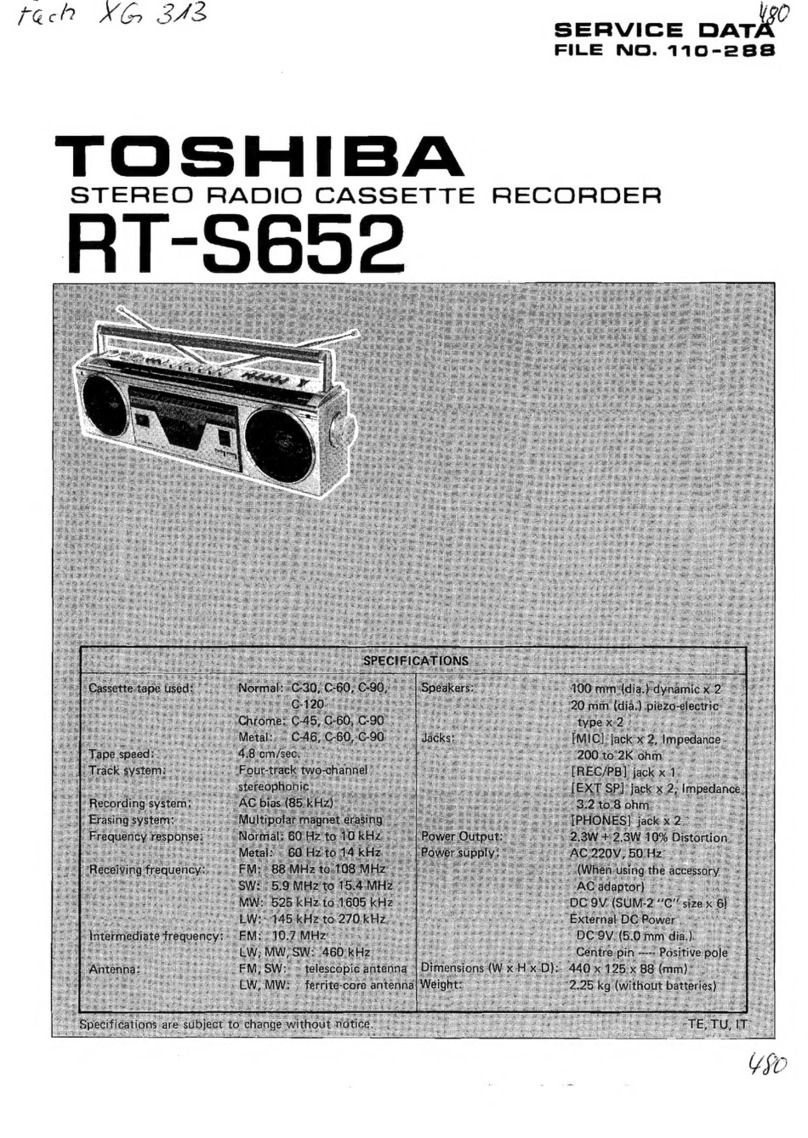
Toshiba
Toshiba RT-200S Mounting instructions
Toshiba
Toshiba SD-V280 User manual

Toshiba
Toshiba PC-E70 User manual

Toshiba
Toshiba RT-S652 User manual

Toshiba
Toshiba KT-S1 User manual

Toshiba
Toshiba SD-V594SU User manual