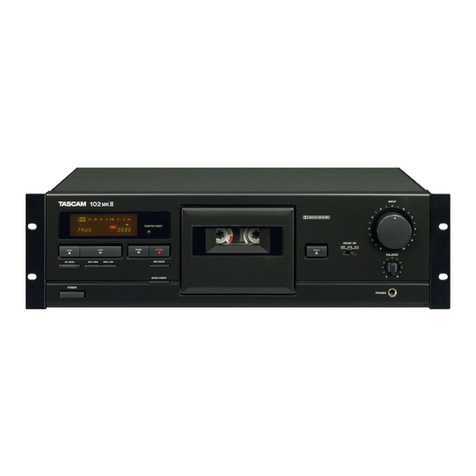
Tascam 122MKIII User manual

TASCAM
TEAC
Professional
Division
(122MKiil)
SERVICE
MANUAL
122MKI/112RMKI/112MKI
Stereo
Cassette
Deck
NOTES
As
regards
the
resistors
and
capacitors,
refer
to
the
circuit
RREAIVS
YUL
CHVES.
GRRE
LUSR
diagrams
and
the
PCB
assy
drawings
contained
in
this
manual.
BEBRUTKCKEAV
*
PC
boards
shown
viewed
from
parts
side.
LFUYbBREISRRHMRANTIET.
+
Parts
marked
with
*
require
longer
deliver
time.
2.
KENOMRILMMOSFODVET.
SBOMCHCIRIK
x
A\
Parts
marked
with
this
sign
are
safety
critical
components.
So
They
must
always
be
replaced
with
identical
components
—
3.
A
MSRSRRBEMATH.
BURT
SCRMIs
+
Py
refer
to
the
TEAC
Parts
List
and
ensure
exact
replacement.
FIEOMMEEBLT<
EA.
*
Parts
not
shown
in
the
parts
lists,
or
parts,
though
listed,
having
4.
UZbKANTWRVBRILRAELCH-EAZHKBMAECLT
no
parts
numbers,
are
not
general
“ready-to-supply*
parts.
RRs
Tuk
tA.
INSTRUCTIONS
FOR
SERVICE
PERSONNEL
BEFORE
RETURNING
APPLIANCE
TO
THE
CUSTOMER,
MAKE
LEAKAGE-
CURRENT
OR
RESISTANCE
MEASUREMENTS
TO
DETERMINE
THAT
EXPOSED
PARTS
ARE
ACCEPTABLY
INSULATED
FROM
THE
SUPPLY
CIRCUIT.
Effective
:
AUGUST,
1993
4A0735
5704066611


T22MKI/TIZRMKU/112MKI
|
1.
SPECIFICATIONS
Tape
:
Compact
cassette
C-30
to
C-90
(Normal/Cr02/
Metal)
Track
Format
:
4-
track,
2-
channel
Head
Configuration
122MKM
=:
~«4-track,
2-channel
Record
(x1)
/repro
(xl)
combination
head
(amorphous)
Half
track
Erase
head
(x1)
(ferrite)
:
4-track,
2-channel
Record
(x1)
/repro
(xl)
combination
rotary
head
(permalloy)
Half
track
Erase
head
(x1)
(ferrite)
:
4-track,
2-
channel
Record/repro
head
(x1)
(permalloy)
Half
track
Erase
head
(x1)
(ferrite)
112RMK
0
112MK
I
Motor
122MK
I
=:
FG
servo
direct-drive
capstan
motor
x1
DC
servo
reel
motor
xl
DC
ancillary
motor
xl
112RMK
0/112MK
I:
DC
servo
capstan
motor
x1
DC
reel
motor
xl
DC
ancillary
motor
xi
Tape
Speed
:
4.8
cm/sec.(1-7/8")
Pitch
Control
:
+/-12
%
(approx.)
Line
Input
-Rear
RCA
jack/front
1/4"
jack
Nominal
input
Level:
-10
dBV
(0.3
V)
Minimum
Input
Level:
-18
dBV
(126
mV)
Input
Impedance:
20k
ohms,
unbalanced
-XLR-type
jack
(standard
on
122MK
I
;
optional
on
112RMK
0.
/112MK
I
~
LA-112
required)
Nominal
Input
Level:
+4
dBm
(1.23
V)
Input
Impedance:
10k
ohms,
balanced
Line
Output
-RCA
jack
(rear)
Nominal
Output
Level:
-10
dBV
(0.3
V)
Maximum
Output
Level:
-2
dBV
(0.8
V)
Output
Impedance:
100
ohms
Load
Impedance:
25k
ohms
or
more
-XLR~type
jack
(standard
on
122MKII
;
optional
on
112RMK
11/112MK
I
—-
LA-112
required)
Nominal
Output
Level:
+4
dBm
(1.23
V)
Minimum
Load
Impedance:
600
ohms
Headphone
Output:
100
mW
(8-ohm
load)
Bias/Erase
Frequency
:
122MK
I1/112RMK
I
:
150
kHz
112MK
0:
100
kHz
{Lt
Equalization
:
3180
7s+70
us
(CrO2/Metal)
3180
7
s+120
us
(Normal)
Reference
Recording
Level
:
250
nWb/m=0
VU
(315
Hz)
(EIAJ)
;x
with
Dolby:
200
nWb/m=-1.
VU
Remote
Connector:
25-pin
D-sub
Power
Requirements
:
USA/Canada:
120
V
AC,
60
Hz
U.K./
Australia:
240
V
AC,
50
Hz
Europe:
230
V
AC,
50
Hz
Japan:
100
V
AC,
50-60
Hz
Consumption
:
122MK
11/112RMK
I:
23
W
112MK
I:
20
W
Dimensions
(WxHxL)
:
482
mm
x
132
mm
(rubber
feet
not
included)
x
356.3
mm
(19"x
5-3/16"
x
14”)
Weight
:
122MK
I1/112MK
1:
8.4
kg
(18-8/16
Ibs.)
112RMK
I:
8.7
kg
(19-3/16
Ibs.)
Typical
Performance
Speed
Accuracy
:
122MK
I:
+/-0.5
%
112RMK
01/112MK
I
:
+/-1.0
%
Wow
&
Flutter
1):
less
than
0.04
%
WRMS
Fast
Winding
Time:
70
sec.(approx.)
with
C-60
Frequency
Response,
Overall
2)
(EIAJ,
without
NR)
122MK
Mf:
25
Hz
to
20
kHz,+/-3
dB
(Metal)
25
Hz
to
19
kHz,
+/-3
dB
(CrO2)
25
Hz
to
17
kHz,
+/-3
dB
(Normal)
:
25
Hz
to
19
kHz,
+/-3
dB
(Metal)
25
Hz8to
18
kHz,
+/-3
dB
(Cr02)
25
Hz
to
17
kHz,
+/-3
db
(Normal)
:
25
Hz
to
19
kHz,
+/-3
dB
(Metal)
25
Hz
to
18
kHz,
+/-3
dB
(CrO2)
25
Hz
to
16
kHz,
+/-3
dB
(Normal)
Distortion
2)
:
less
than
1.0
%,
at
1
kHz,
160
nWb/m
(Metal)
S/N
Ratio
2)
(metal
tape)
122MK
I[/112RMK
I:
60
dB
(without
NR,
ref.
3
%
THD,
WTD)
:
59
dB
(without
NR,
ref.
3
%
THD,
WTD)
68
dB
(with
Dolby-B
NR,
over
5
kHz)
78
dB
(with
Dolby-C
NR,
over
1
kHz)
Channel
Separation
2):
45
dB
or
better
(1
kHz)
Erase
Ratlo
2):
65
dB
or
better
(1
kHz)
112RMK
I
112MK
I
112MK
I

In
these
specifications,
0
dBV
is
referenced
to
1
Volt,
and
O
dBm
is
referenced
to
0.775
Volt.
Actual
voltage
levels
are
shown
in
parenthesis.
1)
Measurements
made
with
TEAC
test
tape
MTT-111
2)
Measurements
made
with
TEAC
blank
test
tape
MTT-
5571
(Metal),
MTT-5562
(CrO2)
and
MTT-5512
(Normal).
‘
Dolby
noise
reduction
and
HX
PRO
headroom
extension
manufactured
under
license
from
Dolby
Laboratories
Licensing
Corporation.
HX
PRO
originated
by
Band
and
Olufsen.
"DOLBY",
the
double-D
symbol
"00"
and
"HX
PRO"
are
trademarks
of
Dolby
Laboratories
Licensing
Corporation.
:
MiChanges
in
specifications
and
features
may
be
made
without
notice
or
obligation.
|
122MKIl/112RMKI/112MKII
@
<
OBIS,
OdBV=1V,
0dBm
=
0.775V
CRRLTOEFS
SROBLL
()
CRLTOES,
Bl)
cOBoOeHI.
FAh-F-S
TEAC
MTT-1ILIZE
HET.
2)
LOMO,
FSU
7
-F-7
TEAC
MTT-5571
(METAL),
MTT-5562
(CrO2),
MTT-5512
(NORMAL)
KkOET.
MRE
LUANG,
PEEK
EBT
SBSH
DET,
*
FVE-*/A
RUFF
yY
ayvRUEXFoeAy
FV-bt
DAF
VY
ard
KFVE-SRShY-KS4evy
ya
-RL-YarPoORPMECERIsMAnTWVET,
HX
TONY
ITY
FANI“GYOSREYT,
*
(KVE-],
(00)
RU
CAX
Fo]
EV
E-SH#ShY
-RIFRYY
YF
A-RV-Y
3
LORSRETCT,
llustration
shows
122MK
Ill.
The
measurements
of
the
three
models
are
the
same.
FFAS
IZZ2MKMOSOTH.
112RMK
il,
112MK
1
SHEETS.

122MKI/112RMKIL/112MKI
|
2.
MECHANICAL
CHECKS
AND
ADJUSTMENTS
PETS
EE
OTE
tS
2-1.
Pinch
Roller
Pressure
(122MK
11,112RMK
Il,112MK
Il,)
.
Attach
a
spring
scale
to
the
pinch
arm.
.
Push
up
the
cassette
switch
(transport
protection
lever),
then
while
holding
the
cassette
switch
up,
press
the
PLAY
button
to
engage
the
pinch
roller
and
capstan
shaft.
3.
Pull
the
spring
scale
in
direction
indicated
in
Fig.
2-1
until
the
pinch
roller
fully
loses
contact
with
the
capstan
shaft;
then
slowly
ease
the
scale
so
the
pinch
roller
moves
back
toward
the
capstan
shaft.
4.
Note
the
reading
on
the
spring
scale
the
moment
the
pinch
roller
again
starts
rotating.
The
scale
should
read
380
to
480
g.
*
Check
both
in
FWD/PLAY
(right
pinch
roller)
and
in
REV/PLAY
(left
pinch
roller)
for
112RMK
I.
we
2-1.
Evy
¥0-sEBH
(122MK
IIl,112RMK
11
,112MK
II)
LOY
F
+
T-BAR.
Zmey
bh
tye
RA
VFO
F-LELAIHHL,
PLAY
#9
VERALT.
FU4+E-KIGTS
MER.
AL
VFO
T-
ALA
IHLEHITS
TL.
BEYF
sao
-SRe
ye
ARGV
Ye
DT
hPOoORecensk
SICPBERPOAM
(H2-1)
5s,
Cv
FF
-0-F
RHUF
ye
TAI
Ys
ve
7
RCERTSEIICRLICRT.
4.CYF
>
0-SREYBHSZLEDBERL,
*
112RMK
Hit,
FWD/PLAY
(4b
yF+a-5),
REV
PLAY
(EUY#F+u-F)
HBTS,
HHS
:
380~480
g
Fig.
2-1
2-2-A.
Tape
Positioning
(122MK
Ill)
Adjustment
Tools
:
*
Head
adjustment
jig
”"A”
:
Part
No.
5736006600
*
Head
adjustment
jig
"B”
:
Part
No.
5736006700
«Erase
head
spacer
;
0.05mm
:
Part
No.
5801357800
O.lmm_
=:
Part
No.
5800556200
0.2mm
_
:
Part
No.
5801197800
jig
B
R/P
head
Fig.
2-2
2-2-A.
F—
FHF
(122MK
Ill)
mBiGR
“Ny
FRIES
A
:
dh
5736006600
“Ny
FSR
B
:
ae
5736006700
“HEN
y
Fe
AN-—+0.05mm
:
dB
5801357800
0.lmm_:
sa@
5800556200
0.2mm
:
gaa
5801197800
jig
B
R/P
head
Fig.
2-3

1.
Adjusting
the
erase
head
height
1).
Set
jig
A
as
shown
in
Fig.
2-2,
then
set
the
deck
to
PLAY
mode.
2).
Confirm
that
jig
B
smoothly
fits
into
the
tape
guide
groove
on
the
erase
head.
If
it
doesn’t,
add
or
remove
the
spacer(s)
between
the
erase
head
and
head
base.
2.
Adjusting
the
R/P
head
height
8).
As
with
the
erase
head,
confirm
using
jig
B;
for
adjustment,
use
height
adjustment
screw
A
(Fig.
2-4).
3.
Adjusting
the
R/P
head
tilt
4),
As
shown
in
Fig.
2-3,
place
jig
B
against
the
head
in
order
to
confirm
the
tilt.
Perform
tilt
adjustment
with
screw
B
(Fig.
2-4)
so
that
the
head
is
at
right
angles
with
respect
to
jig
B.
5).
If
tilt
adjustment
screw
B
is
adjusted,
revert
to
3),
then
confirm
again.
4,
Adjusting
R/P
head
azimuth
6).
As
shown
in
Fig.
2-5,
hook
up
the
measuring
instruments.
7).
Play
back
the
10
kHz
signal
on
test
tape
MTT-256,
then
adjust
playback
azimuth
adjustment
screw
C
(Fig.
2-4)
so
that
the
phase
difference
between
L
and
R
channels
is
0°
.
8).
If
azimuth
adjustment
screw
C
is
turned
more
45°
,
revert
to
3),
then
reconfirm.
5.
Confirming
the
tape
travel
9).
When
mirror
tape
MTT-902
is
run
in
PLAY
mode,
see
that
the
tape
is
free
from
curl
at
each
guide
portion.
10).
If
the
tape
is
curled,
fine-adjust
the
R/P
head
height
using
screw
A
[or
adjust
the
erase
head
height
using
spacer(s)]
then
revert
to
6)
and
reconfirm.
REC
head
REPRO
head
REC
azimuth
adj.
screw
screw
A
screw
B
Fig.
2-4
|
122MKI/112RMKI/112Mk1
LARA
y
FORSHEE
1).
M2-290k5KHBAZtY
LY
PLAYE-
FictS,
2).
BEBABEA
vy
FOF
-T+H4
FRIKAZL-AKAST
tEHRTS.
ZAC,
FEN
FEA
Yy
FeXK—
ZI
HSR
AN-PEBMERIRETSCERLOABTS.
2.
R/PN\y
FOR
SRS
3).
BEA»
FERRIS
RB
CHL,
BRUBSBBRTA
(BI2-4)
i
kYAS5.
3.
R/PX»
FOF
bE
4).
M2-3D04
5RGBBENY
FICMSCTCF
VE
SHBL
A
y
FRBRBICWOCTHBIRZEDIF
HV
hBRRIB
(RI2-4)
CHT.
5).
FUbRBAY
BEBE
LEBER.
3)
AiR
tHe
_
$SHRRRTS.
4.
R/PA»y
KOT
YT
ARS
6).
M2-5
O45
CHEB
3.
7).
FAh*F-PMTT-2560
10kH2
4B
LT,
Lohé
Reh
ORBEA
0°
MAL
ICRET
YL
TAREAIC
(M2
-4)
CHET.
8).
FY
VARBALY
Ce
45°
DEBRA
KBSIA.
3)
Hic
RO
tHURERERRT
4.
5.
7
-FET
ORR
9).
PLAYS-
FCI
5—+-F-PMTIT-92e#F
aE
%.
BAT
FRCF-PSOA-NARMOCLEHBY
SZ,
10).
A-V
L
TW
SBS,
R/PN»
FORSEAY
ACHE
%
(EkMAKNy
FORSEAN-VCHE)
UR
6)
BicROtNHOBEREHERT
SZ.
Oscilloscope
DECK
under
test
OUTPUT
O°finphase)
45°
=
90°
—-
135°.
180
“(out
of
phase)
(LB)
(sot)
Fig.
2-5
|
|

12Z2MK/TIZRMKU/TI2ZMKI
|
2-2-B.
Tape
Positioning
(112RMK
Il)
Adjustment
Tools
:
«Head
adjustment
jig
"A”
:
Part
No.
5736006600
«Head
adjustment
jig
"B”
:
Part
No.
5736006700
*R/P
head
spacer
;0.05mm
:
Part
No.
5801357700
0.lmm_:
Part
No.
5800595000
0.2mm
=:
Part
No.
5800595100
Fig.
2-6
1.
Adjusting
the
erase
head
height
1).
Set
jig
A
as
shown
in
Fig.
2-6,
then
set
the
deck
to
FWD/PLAY
mode.
2).
Confirm
that
jig
B
smoothly
fits
into
the
tape
guide
groove
on
the
FWD
erase
head.
If
it
doesn’t,
adjust
Allen
nut
A
shown
in
Fig.
2-6.
3).
Set
the
deck
to
REV/PLAY
mode,
and
in
a
similar
way,
adjust
the
REV
erase
head
using
Allen
nut
B.
4).
After
adjustment
is
complete,
repeat
FWD/PLAY,
and
REV/PLAY
for
reconfirmation.
2.
Adjusting
the
R/P
head
height
5).
As
in
the
confirmation
of
the
erase
head
height,
confirm
the
R/P
head
height
in
FWD/PLAY
and
REV/PLAY
modes
using
jig
B.
*If
the
head
is
both
high
(or
low)
in
FWD
and
REV
modes,
replace
the
spacer
under
screws
C
and
D
(Fig.
2-6)
with
a
thin
(or
thick)
one.
(Add
or
remove
the
same
number
of
spacers
with
the
same
thickness
for
both
screws
C
and
D.)
«If
jig
B
smoothly
fits
into
the
guide
groove
in
both
FWD
and
REV
modes,
or
the
height
is
opposite
(example:
high
in
FWD
mode
and low
in
REW
mode),
it
should
be
deemed
acceptable.
2-2-B.
F-FHTT
(112RMK
II)
mtiaR
*\y
FBR
A
:
Ga
5736006600
“Ny
FHSS
B
:
da
5736006700
°R/PAy
Fs
AN-—F
0.05mm
:
doe
5801357700
0.lmm_:
gaa
5800595000
0.2mm
_:
gaa
5800595100
jig
A
REV
erase
head
screw
F
1
Hey
FORSHEE
1).
2-69
£54
RAStY
BLL
FWD/PLAY€-
Fiz
To
2).
BEBAFWDABEA
»y
FOF
-—
7-H
PRI
AA-K
CASZCEXHBRTS.
ZH
CHOBE,
M2-6OnBty
hAFBET3Z.
3).
REV/PLAY
€~
FICUT,
BRI
REV
RIBE
»
FOR
SeKht»
bBCABTAZ.
4).
S49.
FWD/PLAY,
REV/PLAY
£0358
L
CHEER
tZo
2.
R/P\y
FORSRS
5).
BHkN»y
FORSHBe
Hic.
FWD/PLAY,
REV/
PLAYS—
KI<BU4R/PAy
KORSetKREBCHEBT
bo
+
FWD,
REV
CA
»
FORSPHECBY
BS.
RIC,
D
(2-6)
DFOAN-4-FRBOMWO
Bw)
HOKRAS.
(C,
DEMUCESOAZN-+F
—-
SAMARAS
BISz2&)
,
*
FWD,
REV,
EBSA
FRI
AL-XKASEBE
ALFWD,
REV
CeqSoet
(i):
FWD,
REWER
Eu)
OBS
OK
LETS,

3.
Adjusting
the
R/P
head
azimuth
6).
Hook
up
the
measuring
instruments
as
shown
in
Fig.
2-5.
7).
Play
back
the
10
kHz
signal
on
test
tape
MTT-256
in
FWD/PLAY
mode,
then
adjust
FWD
azimuth
adjustment
screw
E
(Fig.
2-6)
so
that
the
phase
difference
between
the
L
and
R
channels
is
0°
.
8).
Likewise,
adjust
REV
azimuth
adjustment
screw
F
so
that
the
phase
difference
in
REV/PLAY
mode
is
O°.
9).
If
azimuth
adjustment
screw
E
or
F
is
turned
more
than
45°
,
revert
to
5),
then
reconfirm.
10).
When
mirror
tape
MTT-902
is
mm
in
FWD/PLAY
and
REV/PLAY
modes,
see
that
the
tape
is
free
from
curl
at
each
guide
portion.
At
the
same
time,
see
that
the
tape
comes
into
contact
with
the
lower
guide
of
the
R/P
head
during
FWD
mode
and
that
the
tape
comes
into
contact
with
the
upper
guide
of
the
R/P
head
during
REV
mode.
11).
If
the
tape
is
not
traveling
as
described
above,
fine
-adjust
Allen
nuts
A
and
B
on
the
erase
head,
then
revert
to
6)
and
reconfirm.
2-2-C.
Tape
Positioning
(112MK
Il)
Adjustment
Tools
:
*
Head
adjustment
jig
"A”
:
Part
No.
5736006600
¢
Head
adjustment
jig
"B”
:
Part
No.
5736006700
°
Erase
head
spacer
;
0.05mm
:
Part
No.
5801357800
0.lmm
:Part
No.
5800556200
0.2mm
_
:
Part
No.
5801197800
*R/P
head
spacer;
0.05mm
:
Part
No.
5801357700
O.lmm
=:
Part
No.
5800595000
0.2mm
=:
Part
No.
5800595100
1.
Adjusting
the
erase
head
height
1).
Set
jig
A
as
shown
in
Fig.
2-7,
then
set
the
deck
to
PLAY
mode.
2).
Confirm
that
jig
B
smoothly
fits
into
the
tape
guide
groove
on
the
erase
head.
If
it
doesn’t,
add
or
remove
the
spacer
(s)
between
the.
erase
head
and
head
base.
2.
Adjusting
the
R/P
head
height
3).
As
with
the
erase
head,
confirm
using
jig
B,
and
make
adjustment
using
spacer(s).
3.
Adjusting
the
R/P
head
azimuth
4).
As
shown
in
Fig.
2-5,
hook
up
the
measuring
instruments.
5).
Play
back
the
10
kHz
signal
on
test
tape
MTT-256,
then
adjust
the
azimuth
adjustment
screw
(Fig.
2-7)
so
that
the
phase
difference
between
the
L
and
R
channels
is
0°
.
6).
If
the
azimuth
adjustment
screw
is
turned
more
than
45°
,
revert
to
3),
then
reconfirm.
|
122MKI/112RMKI/112MKI
3.
R/PN\y
FOV
Y
7
ARS
6).
M2-5O
45
MERLE
SZ.
7).
FWD/PLAY
€—-
FGF
AheF—-—F
MTT-256@
10kHz
=REULT,
Leh
¢
Rch
OfBEA
0°
KH
ZKIIZFWD
FAY
YT
ARBARLE
(2-6)
STS.
8).
eZ,
REV/PLAY
©
—
FECHA
0°
KAZ
KSI
REVA7
YVAMSBAY
FERS
4S,
9).
FYTARBRAVESKILZFH45°
CEB
AtrewBeald.
5)
HACK
tnNOUBAREHeRS
3.
4.7
-THPFORR
10).
FWD/PLAY,
REV/PLAY€-
F@i53-—°F-7
MTT
~W2SEASHKLE,
BAL
FRCT-TOA-—
WAH
WItSHRTS,
Ek.
FWDRK,
R/PA»
FO
FOR
4
Fic,
REVER
R/PN\»y
FOLOW4
Fic
F—-TOY4re
SLELHRTS.
11).
EIDE
GIF
—-
TREAT
LTO
UOBSI,
BEN
Y
F
OAT»
bA,
BCRAB
LEAK,
6)
HicRo
tne
EBERT
SZ.
2-2-C.
F-FH#T
(112MK
1)
mesieR
*”\y
FSSA
:
ax
5736006600
*\y
FRSEB
:
GB
5736006700
“BEN
y
Fe
AN-+F
0.05mm
:
de
5801357800
O.lmm
:
gaat
5800556200
0.2mm
_
:
gud
5801197800
°R/PN»y
Fe
AN—¥F
0.05mm_
:
ge
5801357700
O.lmm
:
gu
5800595000
0.2mm
:
and
5800595100
lL
HeAy
FORSRS
-
1).
M2-7TOLFCHBASLY
LY
PLAYE—
Feo
4,
2).
BEBAWEA
vy
FOF
-T°HT
FRICZL—-KEASZC
ces
4.
EATIWOBS,
FEN
FeNy
Fe
ACIS
AN-FREBMERLRATS
CER
LORBKTS.
2.
R/P\
y
FORASBS
3).
Bk
y
FERRIC
SBCHBL.
BRDMEN:
ECR
RI
AN-+CHT35.
R/P
head
azimuth
adj.
jig
B
screw
erase
Feead
Fig.
2-7

122MKI/11Z2RMKU/112MKIl
|
4.
Confirming
the
tape
travel
7).
When
mirror
tape
MTT-902
is
run
in
PLAY
mode,
see
that
the
tape
is
free
from
curl
at
each
guide
portion.
8).
If
the
tape
is
curled,
adjust
the
erase
head
height
using
spacer(s),
then
revert
to
4)
and
reconfirm.
2-3.
Reel
torque
(122MK
Ill,
112RMK
Il,
112MK
II)
1.
Take-up
torque/back
tension
1).
Set
up
the
cassette
torque
meter
(MTT-8111),
then
set
the
deck
to
PLAY
mode
(FWD/PLAY
mode
in
the
case
of
the
112RMK
I)
and
read
the
value
on
the
torque
meter.(If
the
reading
has
a
deflection
{the
pointer
swings],
use
the
center
value.)
The
standard
range
is
as
follows:
2).
Likewise,
put
the
cassette
torque
meter
(MTT-8121)
to
the
112RMK
I,
then
set
the
deck
to
REV/PLAY
mode
and
read
the
value
on
the
torque
meter.
Take-up
torque:
25
to
65
g*cm
Back
tension:
122MK
I,
112RMK
0;
6
to
10
gecm
112MK
If;
2
to
6
g*cm
2.
F.FWD/REW
torque
Set
up
the
cassette
torque
meter
(MTT-8242),
then
measure
the
starting
torques
in
F.FWD
and
REW
operations,
respectively.
F.FWD/REW
torque:
80
g*cm
or
more
2-4.
Tape
speed
(122MK
Ill,
112RMK
Il,
112MK
It)
a
.
As
shown
in
Fig.
2-8,
connect
the
frequency
counter.
.
Load
the
test
tape
MTT-111N.
3.
Let
the
capstan
motor
rotate
in
PLAY
mode,
then
leave
it
as
it is
for
at
least
one
minute
to
warm
it
up.
4.
Set
the
PITCH
CONT
switch
to
OFF.
5.
Play
back
the
middle
section
of
the
test
tape,
then
adjust
trimmer
resistor
Rl
(Fig.
2-9)
on
the
P.CONT
PCB
so
that
the
frequency
counter
reads
3000+5
Hz.
6.
Set
the
PITCH
CONT
switch
to
ON,
then
set
the
PITCH
CONT
knob
to
the
center.
7.
Play
back
the
middle
section
of
the
test
tape,
then
adjust
trimmer
resistor
R2
(Fig.
2-9)
on
the
P.CONT
PCB
so
that
the
frequency
counter
reads
3000+5
Hz.
8.
Upon
completion
of
adjustment,
confirm
that
the
following
value
is
obtained
at
the
beginning
and
end
of
the
tape.
iS)
Speed
variations:
3000+
45
Hz
Fluctuation
range:
within
30
Hz
3.
R/PNy
FOV
YTV
ARSE
4).
M2-5DO
£5
CMEREERT
S.
5).
FAheF-—T
MTT-256
0
10kHz4#
B+
UT,
Leche
Rch
OMIM
0°
LEAZKIKIYPTARBRY
(M2-7)
S
wT
BS.
6).
TYVARBALS
45°
OEMS
eels,
3)
Bice
DtNUEEREERT
3.
4.7
-
THETFORD
7).
PLAYE—
FCI
F—--F-F
MTT-M2e#TStKE
%.
BAT
FRCF-FOA-NARMOCLESRATS.
8).
A-VLTWSHSIZ,
HEN
y
FOMSEAXN-Y
CHE
Lik,
4)
RcR0tnNUKREHEHRT
AS,
2-3.
U-Ibs
hIVD
(122MK
Iil,1172RMK
Il,172MK
II)
LFIAFT
YT
Oh
RDF
YY
ary
1).
Aey
be
h7-2x-F
(MTT-8111)
SBBL,
PLAY
€-—
F
(112RMK
ld,
FWD/PLAY€—-
F)
2
LT
hab
Je
A-POBWERE.
HNOHSHBSUHOML
TS)
RARE
ls
FEC OIE
Y
2).
1IZRMK
Did,
BRIA
be
hI)
X-F7
(MTT-
8121)
HBL.
REV/PLAY€—
FUTHWFZ
+
X-
9
OIE
0
FAITFTIS*
bNMZ
:25~65
ge-cm
NyIFvY
say
:122MKI,
112RMKI
;6~10
g-cm
112MK
I;
2~
6
g*cm
2.
F.FWD/REW
hibZ
Atty
he
bFZ-X-H
(MTT-8242)
SHIAL.
FFWDH
TEE
LU
REW
SEO
b
V7
EENSCHHET
So
F.FWD/REW
ha7
:80
g>cmuk
2-4.
7
-TRE
(122MK
IIl,112RMK
11,112MK
I)
1,
B2-8D4
512,
ARRAY
Y
SERS
S.
2.7
Ab
+
F-7T
MIT-lLIINERSS
SQ
3.
PLAYE-—FC++7APY-S-F
EBS.
VA-
lv
TI
VTFSERBIZ,
DIK
EHIFMTOFEKLTS<
©
4.
PITCH
CONT
A4
»
FE
OFFS.
5.
FA
bh
SF
-TOPMREBE
L,
ARRAY
YY
fA
3000
£5
Hzit%Sk5tc
P.CONT
PCBOWBICIE
R1
(2-9)
ZBETS.
6.
PITCH
CONT
24
y
F#ONIZL,
PITCH
CONT
32
HE
Rize
7
bo
S.
,
7.
FA
SF
—TOPMMEGA
L.
ABBA
Dv
¥
D182
3000
+5
HzicwSk5lz
P.CONT
PCBOMEIEIH
R2
(W2-9)
2B
S.

\
9.
Confirm
that
the
frequency
is
2700
Hz
or
less
when
the
PITCH
CONT
knob
is
set
to
minimum
with
the
PITCH
CONT
switch
ON
and
3300
Hz
or
more
when
the
PITCH
CONT
knob
is
set
to
maximum.
Frequency
Counter
Wow
&
Flutter
Meter
DECK
under
test
OUTPUT
2
Fig.
2-8
2-5.
Wow
and
flutter
(122MK
Ill,
112RMK
HI,
112MK
#)
Note
:
Measurements
should
be
made
in
PLAY
mode
at
the
beginning,
middle
and end
of
the
tape,
respectively.
(However,
avoid
the
first
graduation
on
the
cassette
shell
for
the
beginning
and
end
of
the
tape.)
J.
As
shown
in
Fig.
2-8,
connect
the
wow
&
flutter
meter
to
the
deck.
2.
Play
back
the
test
tape
MTT-111N.
3.
Measure
the
wow-
flutter
value.
The
standard
range
is
as
follows:
within
0.06%
(WRMS)
2-6.
Adjusting
the
quick
reverse
voltage
(112RMK
Il)
1.
Connect
the
DC
voltmeter
between
TP2
(Fig.
2-10)
on
the
CONT
S
PCB
and
GND.
2.
When
blank
tape
MTT-5512
is
played
back
in
the
REV
/PLAY
mode,
adjust
R26
(Fig.
2-10)
on
the
CONT
S
PCB
so
that
the
voltage
at
TP2
reads
2.5
V.
CONT
S
PCB
t
ES
Fig.
2-10
TEAC-00347
/
DRUCK
1
|
122MkK0/112RMKI/112MKI
8.
ABR.
F-TSORRDLSRD
OT,
FacOseonser
&
EHTS
So
TRE
Wa
:
3000445
Hz
ee
:30
HzLA
9,
PITCH
CONT
A4
y
FONG.
PITCH
CONTDESER/
LES
2Z700HZWK,
MARLEE
3300HzUETHS
tte
P.
CONT
PCB
Fig.
2-9
2-5.99
*VIvIF
(122MK
Iil,172RMK
II
,112MK
II)
ER
:
MEUBERICKLYN,
F-TFORBO,
PHB.
SRD
OD
CENENTH
TCR
SU.
GEL,
WEY
bes
-
TOAD
teed)
O1
BBY
itR<)
1.
B2-8DE5K,
IDTV
GV
It
2A
-PEF
v
FEET
SZ.
2FAh+*F-PMTT-LLINABETS,
399°
75
yFEMET
S.
BHBIKOW).
0.06
%LLA
(WRMS)
2-6.974
997°
UN-ABERE
(112RMK
II)
1.
CONT
S
PCBOTP2
(Mi2-10)
&
GND
DCBHHEE
BEF
So
2.
REV/PLAY€~-
FG,
F747
*F-TF
MTT-905
SB
LEE,
TP2OREM
25ViITMSKIGI
CONT
S
PCBO
R26
(Bj2-10)
HET
S.
3.
AMPLIFIER
SECTION
CHECKS
AND
ADJUSTMENTS
FVYPRORRLBES
TAPE
:
MTT-256
(dB)
+3
+3
)
0
-3
-3
ee
er
ee
63
315
10k
(Hz)
Fig.
3-1
Playback
frequency
BE
AiR
(4B)
+1 +1
a
aaa
-3
-3
(a
ee
20
400
20k
(Hz)
Fig.
3-2
Monitor
frequency
response
E=Y
—
ARSE
——
DOLBY
NA:
IN
»«-
DOLBY
NR:
OUT
63
400
12.5k
14k
vee
(Hz)
T12MK
11
|
122K
ill
112RMK
It
Fig.
3-3
Overall
frequency
response
SARS
10

122MKI/112RMKI/112MKI
|
MAIN
PCB
L102
L202
TP1
O
O
TP2
Ri61
R261
METER
AMP
PCB
Ri2~
=
R11
Fig.
3-4
Adjustment
and
test
point
locations
BRETARKIY
MEM
11
TEAC-00347
/
DRUCK
2
R122
Day
L101
(KZ)
L201
SAMY
O
R117
R222
®)
R217
Oscilloscope
Speaker
Amplifier
Fig.
3-6
Oscillator
Oscilloscope
Distorion
Analyzer
Amplifier
|
Speaker
Attenuator
DECK
under
test

|
122MKI/112RMKI/112MKi
Oscillator
AC
voltmeter
Attenuator
DECK
under
test
TEST
LOAD
RESISTORS
Fig.
3-8
Frequency
Counter
Oscillator
Oscilloscope
O°(inphase)
45°
90°
135°
180°
(
4B)
(i048
)
Fig.
3-10
13

12Z2MKl/
TIZAMKU/TIZMKL
|
3-1.
Precautions
3-1.
EB
l.
Before
performing
adjustments
and
checks
clean
and
LFV
TROBE
-
HERO.
F-VTEARORE
LIBRE
demagnetize
the
entire
tape
path.
2TH,
2.
Indication,
for
example,
"R122/R222"
means
that
R122
2.
R122/R222
cso
SNTOSMBi,
Loch/Rch*ERLEF.
is
for
Lch,
R222
is
for
Rch.
8.
OdBm
=
0.775V,
OdBV
=
LOV
THRU
THEFT,
3.
0
dBm
is
referenced
to
0.775
V.
0
dBV
is
referenced
A
UNITE.
ADT
YE-FYR
IMQUEODOEBALT
to
10
V.
<
PEAS
4,
The
AC
voltmeter
used
in
the
procedures
must
have
5.
FICHE
RORBA,
FA
PHY
bBELVHREMIIN
an
input
impedance
of
1
MQ
or
more.
38-4EBRMLT<K
HAWS
5.
Unless
otherwise
specified,
refer
to
Fig.
3-4
for
location
6.
FSICFEROMUEO.
F-BLUAT
y
FHAILOFF
ICL
THY
of
test
points
and
adjustment
points.
TCKRSU,
6.
Unless
otherwise
specified,
leave
all
keys
and
switches
in
the
OFF
position.
3-2.
Playback
System
B45
Test
Mode
:
PLAY
MONITOR
switch
:
AUTO
input
Signal
Adjustment
Point
|
Measurement
Method
/
Vaiue
Adjusted
For
AES
PR
WEA
-
RHE
MTT
—
150
R122/R222
122MK
II,
112RMK
I
:
TPS/TP6
:
—
6dBm
112MK
I
:
TP3/TP4
:
~
6dBm
OUTPUT
cont.
|
OUTPUT
(RCA,
Lch)
:
-
11dBV
frass
|
OUTPUT
(RCA,
Rch)
:
~
11dBV
After
adjusting,
do
not
move
the
OUTPUT
cont.
(Nominal
position)
Preliminary
PENG
>
ERE
Adjustment
Item
be
9
=|
Connection
(#2)
:
Fig.
3-5
1.
Reproduce
reference
level
EBL
AI
Connection
(#2)
:
Fig.
3-6
OUTPUT
(RCA)
:
WBE,
OUTPUTSVESSMMSUVIL,
HUE)
Same
output
level
at
10
kHz
and
315
hz
10kHz
DHA
LAIVASBISHZOWAL
VER
MTT
—
256
R117/R217
URES
EFC
eo
few
ownen
3.
Level
Difference
Same
as
above
Same
as
above
Check
only
within
3
dB
between
Channels
|
faJ_£
cia
(within
the
limits
of
reproduce
frequency
F
»
RIVALS
response)
(FE
AHHERISAIZ
tT)
4.
Level
Fluctuation
|
Same
as
above
Same
as
above
Check
only
63
Hz~6.3
kHz,
within
2
dB
,
UNIVER
falE
falE
6.3
kHz~10
kHz,
within
3
dB
f)
5.
Reproduce
S/N
Same
as
above
Check
only
Measure
output
when
leader
tape
is
played
ratio
jE
FS
SN
EE
Connection
(##2)
:
Fig.
3-6
2.
Repro.
Frequency
Response
BERRA
back
with
the
unit
set
for
nominal
outme
level,
and
compare
this
reading
with
nominal
output
level.
BEER.
U-S-
-
F-TSEBELKE
BDI
A
K+
VAIVMIBIEWAVAVERATE
FOIE.
S/N
(120
us):
46
dB
or
more
S/N
(70
us):
48
dB
or
more
Deference
between
channels:
4
dB
or
les

|
122MKI/112RMKI/112MKI
3-3.
Monitor
System
£=9—-%
Test
Mode:
STOP
(unless
otherwise
specified
##I<#E7KO
iE
MEY
)
MONITOR
switch
:
INPUT
Measurement
Method
/
Value
Adjusted
For
NEA
+
Preliminary
Adjustment
Point
em
IE
input
Signal
ATHES
Adjustment
Item
RAB
Pt
OUTPUT
(RCA):
-10
dBV
L,R
After
adjusting,
do
not
move
the
INPUT
controls.
(Nominal
position)
MBAs.
INPUTOFSSIMSKOIL,
GAEL)
INPUT
(Rear,
RCA)
:
OUTPUT
(RCA):
-10
dBV+3
cB
400
Hz/-18
dBV
Connection
(#:##)
:
Fig.
3-7
INPUT
cont.
:
Max.
1.
Minimum
input
level
BhAAL
INPUT
(Rear,
RCA)
:
400
Hz/-10
dBV
2.
Nominal
input
Connection
(###2)
:
Fig.
3-7
level
BRAD
LAI
Same
as
above
VU
meter
indication:
0
VU
fb
Same
as
above
ft
3.
Meter
level
X-F-
VAIL
4.
MPX
FILTER
Connection
(#24)
:
Fig.
3-7
|
INPUT
(Rear,
RCA):
OUTPUT
(RCA)
:
MPX
7
4
LZ
~
MPX
FILTER
sw.
:
ON
19
kHz/-10
dBV
Minimum
output
level
(Effect
:
30
dB
or
more)
BALAI
SSIS
HRS
30dBUED=
&)
L103/L203
5.
XLR
output
level
|Connection
(#€%)
:
Fig.
3-7
{INPUT
(Rear,
XLR):
|
Check
only
OUTPUT
(XLR)
:
XLRBAL
AL
INPUT
sw.
:
BAL
400
Hz/+4
dBm
+4
dBm+1
dB
at
100
kQ
load
(122MK
Ill
only)
(+2.5
dBm+1
dB
at
600
Q
load)
6.
Front
input
Connection
(#2#%)
:
Fig.
3-7
|
INPUT
(Front,
1/4”)
:|
Check
only
OUTPUT
(RCA):
-10
dBV+2
dB
FRONT
AD
400
Hz/-10
dBV
7.
PHONES
output
Connection
(#4)
:
Fig.
3-8
|
INPUT
(Rear,
RCA):
|
Check
only
PHONES
OUT:
PHONES
cont.
:
Max.
400
Hz/-10
dBV
100
mW
or
more
(82
load)
100mWELE
(8
OFF)
level
PHONES
#7)
bul
OUTPUT
(RCA,
XLR)
:
60
dB
or
more
(DIN
AUDIO)
60dBUE
(DIN
AUDIO)
OUTPUT
(RCA,
XLR)
:
Specs
(#148)
:
Fig.
3-2
8.
Monitor
S/N
€=9-S/N
Connection
(#28)
:
Fig.
3-7
INPUT
(Rear,
RCA)
:
20
~20
kHz/-10
dB’
9.
Monitor
frequency
|
Same
as
above
While
alternating
the
oscillator
signal
between
10
kHz
and
400
Hz
by
pressing
the
10
kHz
sw.
on
and
off,
adjust
for
same
output
level
at
TP7.
10
kHz2%4
»y
FEON/OFF
L.TP7
OWA
NMEAURASZESCMETS,
Connection
(#62)
:
Fig.
3-5
10.
Internal
osc.
AMHR
(122MK
Ill
only)
With
REC/PLAY
mode,
press
ADJUST
key,
then
press
OSC
key.
REC/PLAY3ARET..
ADJUST
=
~®ONIZL.
ELTOSC#-#%
ONIZS4,
Set
the
oscillator
to
400
Hz
(10
kHz
sw.
off)
and
adjust
for
-28
dBV
at
TP7.
10
kHzA4
y
FR
OFFIZL.
TPT
OMA
AUL
2
-28dBVILASZKACMBIS.

122MKI/11Z2RMKU/112MKil
|
3-4.
Recording
System
2%
Test
Mode:
REC/PLAY
(unless
otherwise
specified
#I<HE7ROR\
GED
)
MONITOR
switch:
AUTO
Input
Signal
AES
Preliminary
Adjustment
Item
Eb
3t-4]
1.
Bias
OSC
frequency
INA
FT
RFA
112RMK
I
:
Connection
(4%)
:
Fig.
3-9
Test
tape:
MTT-5571
Mode
:
FWD
REC/PAUSE
&
REV
REC/PAUSE
122MK
II,
112MK
I
:
Connection.
(6%)
:
Fig.
3-9
Test
tape
:
MTT-5571
Mode
:
REC/
PAUSE
2.
HX
PRO
coil
HX7o
34tI
Connection
(##%)
:
Fig.
3-5
Test tape
:
MTT-5571
Mode
:
REC/
PAUSE
3.
Rec
azimuth,
Temporary
bias
BET
VTA.
BN
|
Test
tape:
MTT-5512
ATR
(NORMAL)
(122MK
Ill
only)
Connection
(##)
:
Fig.
3-7
.
Bias
set-1
NAT
A+
ty
b-1
Test
tape:
MTT-5512
(NORMAL)
.
Rec
level-
i
Same
as
above
BEVNI-1
fejE
Connection
(#28)
:
Fig.
3-7
|
INPUT
(Rear,
RCA)
:
400
Hz,
10
kHz/
-36
dBV
.
Bias
set-2
INAT
Re
By
b-2
Test
tape:
MTT-5562
(Cr02)
Same
as
above
BE
Connection
(#4)
:
Fig.
3-7
Test
tape:
MTT-5571
(METAL)
Connection
(48%)
:
Fig.
3-7
|
INPUT
(Rear,
RCA):
400
Hz/-14
dBV
.
Ree
level-2
SEVNAI-2
Test
tape:
Same
item
6.
.
Total
harmonic
Connection
(#%)
:
Fig.
3-7
|
Same
as
above Check
only
distortion
fk
ReES
Test
tape:
Same
item
3
and
6.
16
Adjustment
Point
Boks
(0
L3
(for
FWD)
L207
(for
REV)
L3
1102/1202
Connection
(##%)
:
Fig.
3-10
|
INPUT
(Rear,
RCA):
|
R161/R261
10
kHz/-36
dBV
INPUT
(Rear,
RCA):
|
R161/R261
400
Hz,-10
kHz/
-36
dBV
INPUT
(Rear,
RCA):
|
R302/R402
400
Hz/-14
dBV
Ril
Measurement
Method
/
Value
Adjusted
For
WEAR
-
A
Connector
P8
pind:
100+0.1
kHz
122MK
II
:
Connector
P8
pind:
150+0.1
kHz
112MK
I:
Connector
P8
pind:
100+0.1
kHz
TPL/TP2:
Max.
DC
voltage
DC
GERA
OUTPUT
(RCA)
:
Max.
output
level
WAVCURK
OUTPUT
(RCA)
:
Phase
between
Lch/Rch
:
0°
Lech
&
Reh
DEBATE
VIZ
S
KD
IPE
OUTPUT
(RCA)
:
Same
output
level
at
400
Hz
and
10
kHz.
400Hz
&
10kHz
DHDL
AULA
LIKS
ED
HS
OUTPUT
(RCA):
-14
dBV
OUTPUT
(RCA)
:
Same
output
level
at
400
Hz
and
10
kiz.
400Hz
¢
1OkHz
DORAL
NIA
LIZAS
£5
(HS
Same
as
above
fale
OUTPUT
(RCA):
-14
dBV+2
dB
OUTPUT
(RCA)
:
122MK
II,
112RMK
I:
2.0
%
or
less
for
all
tapes.
112MK
1:
2.5
%
or
less
for
all
tape
BF-TFC2ZO“UF
(112MK
Tid.
25%
F

122MKI/112RMKI/112MKI
Adjustment
Item
Preliminary
input
Signal
Adjustment
Point
|
Measurement
Method
/
Value
Adjusted
For
RB
Hef
IGE
AMES
ASAT
MEA
ABE
OUTPUT
(RCA)
:
Specs
(#48)
:
Fig.
3-3
INPUT
(Rear,
RCA)
:
63
Hz
~
16
kHz/
-36
dBV
9.
Overall
frequency
|
Connection
($%)
:
Fig.
3-7
response
Sehr
10.
Level
difference
|
Connection
(#:¢%)
:
Fig.
3-7
between
channels
F
te
RIVER
NILES
DOLBY
NR:
OUT
and
IN
Check
only
OUTPUT
(RCA):
63
Hz
~
6.3
kHz:
within
3
dB
6.3
~
10
kHz:
within
4
dB
INPUT
(Rear,
RCA)
:
63
Hz
~
10
kHz/
-36
dBV
OUTPUT
(RCA):
400
Hz:
within
1
dB
63
Hz
~
6.3
kHz:
within
2
dB
6.3
~
14
kHz:
3
dB
OUTPUT
(RCA):
40
dB
or
more
INPUT
(Rear,
RCA)
:
63
Hz
~
14
kHz/
-36
dBV
Same
as
above
fat
11.
Rec/repro
level
fluctuation
BAL
AILEH
INPUT
(Rear,
RCA):
Leh:
no
signal
Reh:
125
Hz/-10
dB
Record
a
125
Hz
signal
on
Rch
and
note
output
level
Then
invert
tape
and
play
Reh
track.
Check
leakage
level
against
the
output
reference
of
previously
recorded
portion.
Reh
t=
125Hz
OF
SERS
L.
TOHAMHERELNAVLTS,
RIF
-TFEREL,
BELALEORch
OWMHLNIVLOLERETS.
Same
as
above
fale
12.
Track
crosstalk
boy
7h7oR
b-2
13.
Channel
Connection
(#8)
:
Fig.
3-7
|
INPUT
(Rear,
RCA):
OUTPUT
(RCA):
30
dB
or
more
separation
1
kHz
B.PF.
connect
Leh:
1
kHz/-10
dBV
FIle
esNL—
|
1
kHz
B.PF.
He
Rch
:
no
signal
Yay
Find
the
difference
between
the
1
kHz
recorded
portion
(Lch)
and
the
“no
signal”
recorded
portion
(Rch).
UkH2
#RASED
(Loh)
EMME
SHB
(Rch)
LOBEMALKVOKEMETS.
Same
as
above
INPUT
(Rear,
RCA):
|
Check
only
OUTPUT
(RCA):
65
dB
or
more
ied
1
kHz/0
dBV
Record
a
1
kHz
signal
and
rewind
tape
to
mid
point
of
recorded
portion.
Erase
the
recorded
portion
with
no
input
signal
and
find
the
difference
between
the
1
kHz
portion
and
the
“no
signal”
portion.
lkHz
OB
SERER.
F-TERARLT-BEBETS.
KBEMS
LEM
COKEMETS.
14,
Erasure
BER
OUTPUT
(RCA):
MTT-5512
(NORMAL)
:
45
dB
or
more
MTT-5562
(Cr02)
:
47
dB
or
more
MTT-5571
(METAL):
47
dB
or
more
Reference
level
HELV:
-10
dBV
15,
Overall
S/N
#®ES/N
No
signal
Check
only
RES
No
signal
.
L101/L201
SHES
Connection
($£:)
:
Fig.
3-7
Test
tape:
Same
item
8.
OUTPUT
(RCA):
Minimum
bias
leakage
NAT
AR
Specs
(#148)
:
-40
dBV
or
less
16,
Bias
leakage
NAT
ABN
Connection
(#¢)
:
Fig.
3-7
17

122MKIl/112RMKL/T1T2MKI
4.
EXPLODED
VIEWS
AND
PARTS
LISTS
SHR
LN-YURE
EXPLODED
VIEW-1
18

EXPLODED
VIEW!
I-
2
I+
3
I=
4
I=
5
l=
6
I-
7
1-9
I-10
f~lI
1-12
f=13
1-14
1-21
1=22
1=23
124
REFNO.
PARTS
NO.
*5801350900
*58006
12400
*5801
499600
5801348701
*5801566
100
*580
1568500
*580
1568000
*580
1568100
*580
1568200
*580
|
486600
5801501800
5801500700
5801349300
5504676000
*5801342500
5801568400
*5
783773006
*5
783534008
*5730017600
*5
783034020
INCLUDED
ACCESSORIES
LUS]:U.SeA.
[E]:EUROPE
[UK]:U.K.
[C]
CANADA
[J]
:
JAPAN
REFNO.
PARTS
NO.
*5
700140501
*57001
40600
¥*5
700140701
*57803
15015
*5801512200
*5785225000
LA]:AUSTRALIA
DESCRIPTION
BONNET
(B)
SCREW,BONNET
M3X8(BLK)
FILTER,BONNET
[C]
ANGLE
SCREW,
STEP
S=TITE
3X6
ESCUTCHEON,
METER
PANEL,
FRONT
[1
12RMK2}
PANEL,FRONT
[122MK31
PANEL
FRONT
[1
12MK2]}
ESCUTCHEON,
D
P=NI5=A
WINDOW,
CASSETTE
LID,
CASSETTE
KNOB
FOOT
PLATE,
BOTTOM
LENS
€112RMK2]
SCREW,
BIND
BeTITE
MSX6(BLK
ZN)
SCREW,BIND
B=TITE
M4X8(BLK
NI)
SCREW,
BIND
BR=TITE
M3X6
SCREW,BIND
S-TITE
M4X20
DESCRIPTION
OWNER'S
MANUAL(J)
[J}
OWNER'S
MANUAL(F$G)
IC,E]
OWNER'S
MANUALCE)
[EXCEPT
J]
SCREW,
OVAL
COUN.
M5XI5(N1)
WASHER,
5X1
2X3
WASHER,
FIBER
5X1OX0.5T(BLK)
Parts
marked
with
*
require
longer
delivery
time.
|
122MKI/112RMKI/112MKi
19
|
|
!
|

122MKI/112RMKI/112MKIL
_
EXPLODED
VIEW-2
122mKI
,112MKo

EXPLODED
VIEW-2
REF
.NO.
PARTS
NO.
*5801511300
2-2
*5801501500
2-3
*5801510000
2-4
*5801511200
2-5
,*5801501900
2-
6
*5801502400
2-7
*5801510100
2-
8
'*5801344601
2-9
*5801502200
2-10
5225025500
2-11
*5801344701
2-|2
*580
1503000
2-13
*5801343600
2-14
*580
1345000
2-15
*5800620500
2-16
5801503700
2-17
*5801515800
2-18
*5801515900
2-19
*5200362100
*5200362110
*5200362120
2-20
5801412800
2-21
5801503600
2=22
*5800472201
2=23
5801503800
2-24
*580
1502500
2=25
*5200362200
2-2
*5801500500
2-27
*580
1598400
2-28
Vacant
2-29
5801502600
2-30
*5801567600
2=31
*5200362800
232
*5200362700
*52003627
10
*5200362720
2-33
3801567700
5801567800
2-34
5801568300
2-35
*520036
1500
¥*520036
1510
#520036
1520
2-36
5801575000
2-37 *580
1599900
2-38
*580
1567400
239
5801583600
2—40
*520036
1400
#520036
1
420
2=4I
*5801567500
2~42
*5800933500
2=43
*5800933000
2-4
5800933600
(Continued
on
page
26)
DESCRIPTION
SPRING,LOCK
ARM
ARM,
LOCK
SIDE
CHASSIS(L)
ASSY
SCREW,
STEP
ARM,
SWITCH
CHASSIS(R)
,
SIDE
SUB
SIDE
HOLDER
ASSY
HOL
DER(L)
PANEL,
CASSETTE
LED,
SLF601C(ORG)
HOLDER
(R)
PADCUL)
SPACER
HOLDER
ASSY,CASSETTE
DAMPER
PANEL,
TRIM
SPRING(L)
,HOLDER
SPRINGCR)
,HOLDER
P.CONT
PCB
ASSY
[!12RMK2]
P.CONT
PCB
ASSY
[122MK3}
P.CONT
PCB
ASSY
[1
12MK2}
KNOB(BL)
KNOB,
PITCH
CONTROL
ROD,
EJECT
BUTTON,
EJECT
PeNI5-A
LID,
ESCUTCHEON
OP
SW
PCB
ASSY
BRACKET
,PCB
(OP)
SHEET,
PROTECTION
BUTTON(
1)
,
OPERATION
HOLDER,
COUNTER
PCB
JOINT
C
PCB
ASSY
COUNTER
PCB
ASSY
[]12RMK2)
COUNTER
PCB
ASSY
[122MK3)
COUNTER
PCB
ASSY
[1!12MK2]
BUTTON,
OPERATION
[1
12RMK2]
BUTTON,
OPERATION
[122MK3,1
12MK2]
WINDOW
JACK
PCB
ASSY
[11
2RMK2]
JACK
PCB
ASSY
{£122MK3]
JACK
PCB
ASSY
[1
12MK2)
KNOB,
SLIDE
SPRING,
EARTH
HOLDER,
JACK
PCB
KNOB,
ROTARY
VR
PCB
ASSY
[122MG,112RMK2}
VR
PCB
ASSY
[112MK2)
HOLDER,R
VOL
GEAR
B
(122MK3]
GEAR
A
ASSY
[122MK3}
BELT,
TIMING
[122MK3]
Parts
marked
with
*
require
longer
delivery
time.
|
122mMKI/112RMK1/112MKI
Refer
to
Refer
to
Refer
to
Refer
to
Refer
to
Refer
to
Reter
to
Refer
to
Refer
to
Reter
to
Refer
to
Refer
to
Refer
to
pages
40
&
45
pages
40
&
45
pages
40
&
45
pages
42
&
46
pages
38
pages
38
pages
38
&
9
go
ERG
pages
38
&
44
pages
39
&
45
pages
39
&
45
pages
39
&
45
pages
3!
pages
3
oo
2}
Qo
&
&i
21
Other manuals for 122MKIII
3
This manual suits for next models
2
Table of contents
Other Tascam Cassette Player manuals

Tascam
Tascam 112mkII User manual

Tascam
Tascam CC-222 User manual

Tascam
Tascam D00935220B User manual

Tascam
Tascam 122MKIII User manual

Tascam
Tascam 202MKVI User manual
Tascam
Tascam 102MKII Guide

Tascam
Tascam 122MKIII Guide

Tascam
Tascam 202mkV User manual

Tascam
Tascam 302 User manual

Tascam
Tascam 122 mk III User manual

Tascam
Tascam 122MKIII User manual

Tascam
Tascam 112mkII User manual

Tascam
Tascam 112mkII User manual

Tascam
Tascam 202mkIII Guide
Tascam
Tascam 102MKII User manual

Tascam
Tascam PortaStudio 424 User manual

Tascam
Tascam 102MKII User manual

Tascam
Tascam 302mkII Guide

Tascam
Tascam 302mkII User manual

Tascam
Tascam 202mkIII User manual