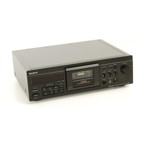
Sony TC-K333ESA User manual

TC-K333ESA/K9S0ES
SERVICE
MANUAL
*
Dolby
noise
reduction
and
HX
Pro
headroom
extension
manufactured
under
license
from
Dolby
Laboratories
Licensing
Corporation.
HX
Pro
originated
by
Bang
&
Olufsen.
“DOLBY”,
the
double-D
symbo!
DO
and
"HX
PRO”
are
trademarks
of
Dolby
Laboratories
Licensing
Corporation.
SPECIFICATIONS
Recording
system
4-track
2-channel
stereo
Fast
winding
time
Approx.
90
sec.
(with
Sony
C-60
cassette)
Bias
AC
bias
Heads
Erasing
head
x
1
(S&F
head)
Recording
head
x
1
(LA
head)
Playback
head
x
1
(LA
head)
Motors
Capstan
motor
x
1
(direct
-drive
linear
torque
BSL
motor)
Reel
motor
x
1
(DC
motor)
Type
IV
(Sony
Signal-to-noise
ratio
(at
peak
level)
Type
Il
Type
|
Metai-S)
(Sony
UX-S)
(Sony HF-S)
61
dB
59
dB
57
dB
Measured
at
peak
level
weithted
without
NR.
The
S/N
is
improved
by
about
15
dB
at
500
Hz
and
by
about
20
dB
about
1
kHz
with
Dolby-C
NR
on,
and
by
5
dB
at
1
kHz
and
by
10
dB
about
5
kHz
with
Dolby-B
NR
on.
Cassette
(Dolby
NR
OFF)
1.3%
(with
Sony
Metal-S
250
nWb/m,
315
Hz,
3rd
H:D.)
Frequency
response
(Dolby
NR
OFF)
Type
IV
cassette
15
-
22,000
Hz
(+3
dB,
IEC)
(Sony
Metal-S)
15
-
16,000
Hz
[+3
dB
(-4dB
recording)]
Type
Il
cassette
15
-
20,000
Hz
(#3
dB,
IEC
(Sony
UX-S)
Type
|
cassette
15-4
Hz
(+3
dB.
|
(Sony
HF-S)
8,000
Hz
(+3
dB,
IEC)
+
0.04%
W.Peak
(IEC)
0.022%
W.RMS
(NAB)
+
0.065%
W.Peak
(DIN)
Line
inputs
Sensitivity
0.16
V
(phono
jacks)
Input
impedance
47
k
ohms
CD
DIRECT
INPUT
Input
impedance
47
k
ohms
Harmonic
distortion
Wow
and
flutter
Inputs
Model
Name
Using
Similar
Mechanism
TC-K333ESG
Tape
Transport
Mechanism
Type
AEP
Model
TC-K990ES
E
Model
TC-K333ESA
TCM-200D10
Outputs
Line
outputs
(phono
jacks)
Rated
output
level
0.5
V
at
a
load
impedance
of
47
k
ohms
Load
impedance
Over
10
k
ohms
Output
level
0-3
mW
ata
load
impedance
of
32
ohms
AEP
model:
|
220
-
230
V
AC,
(or
240
V
AC
adjustable
by
Sony
personnel),
50/60
Hz
E
model:
120,
220,
or
240
V
AC
adjustable,
50/60
Hz
Power
consumption
31
W
Dimensions
Approx.
470
x
140
x
380
mm
(w/h/d)
(185%
x
55%
x
15
inches)
including
projecting
parts
and
controls
Approx.
12.0
kg
(26
lbs
8
oz)
Model
for
other
countries:
Approx.
11.2
kg
Headphones
(stereo
phone
jack)
General
Power
requirements
Weight
Supplied
accessories
Audio
connecting
cords
(2)
Screws
(8)
Wireless
remote
commander
(1)*
Sony
SUM-3(NS)
batteries
(2)*
*
Not
supplied
with
model
for
European
countries
Design
and
specifications
are
subject
to
change
without
notice.
Note
This
appliance
conforms
with
EEC
Directive
87/308/EEC
regarding
interference
suppression.
STEREO
CASSETTE
DECK
SONY.

TC-K333ESA/K990ES
TABLE
OF
CONTENTS
Section
Title
Page
Specifications
Ge?
Jb
Settee:
eae
ve
Seg
ghia
OL
OL
WS
BOS
Sl
WYO
S.
BLES.
Be:
-orkeNeve
lt
Servicing
Note
SW
gi
erate
se
eRe
here.
AOS
wiles
len
elie,
Siieiie!
Solel
3)
euahies
Oho.
oer
18
2
Model
Identification
#0
MGS
S080
<0
BD:
WO
(O Oc
le
oreo:
ee
corer
ere
6
ce:
3
SECTION
1.
GENERAL
--------
"eee
ee
eee
cece
eeee
4
SECTION
2.
DISASSEMBLY
...........-.--.02205-
8
SECTION
3.
ADJUSTMENTS
3-1.
Mechanical
Adjustments
--+--+++++++eeeeee-
10
3-2.
Electrical
Adjustments
-----+-+++s+re
erro
ees
12
SECTION
4.
DIAGRAMS
4-1-1.
10502,
505
(CX20188)
Pin
Functions
-----
17
4-1-2.
IC601
(M50940-313SP)
Pin
Functions
-----
18
4-1-3.
IC801
(M50964-226SP)
Pin
Functions
-----
19
4-1-4.
1C881
(HD404240A31S)
Pin
Functions
----:
20
4-2.
Circuit
Boards
Location
-----+-+++++++++e:-
20
4-3,
IC
Block
Diagrams
SSL
en
ie
ee
es
een
Sw
seehe
Oe
arele
6
®u8
ec
ee
21
4-4.
Semiconductor
Lead
Layouts
--+--+-+-+++-++:
22
4-5.
Block
Diagram
--+++
sees
e
sees
eee
eee
e
eee
ees
23
4-6.
Printed
Wiring
Boards
(Audio
Section)
27
4-7.
Schematic
Diagrm
(Audio
Section)
--------:
31
4-8.
Schematic
Diagrm
(Syscon
Section)
-----:--
35
4-6.
Printed
Wiring
Boards
(Syscon
Section)
---
39
SECTION
5.
EXPLODED
VIEWS
5-1.
Overall
Section
--+++
ccs
rere
tere
ee
eee
ee
eee
43
5-2.
Front
Panel
Section
--++-++++ct
eerste
ee
eeee
44
5-3.
Chassis
Section
-s+crr
creer
cece
eee
ee
eeees
45
5-4.
Mechanism
Section
-1
(TCM-200D10)
--------
46
5-5.
Mechanism
Section
-2
(TCM-200D10)
--------
47
SECTION
6.
ELECTRICAL
PARTS
LIST
-::::---
48
SERVICING
NOTE
Flexible
Circuit
Board
Repairing
@
Keep
the
temperature
of
the
soldering
iron
around
270°C
during
repairing.
®
Do
not
touch
the
soldering
iron
on
the
same
con-
ductor
of
the
circuit
board
(within
3
times).
®
Be
careful
not
to
apply
force
on
the
conductor
when
soldering
or
unsoldering.
Notes
on
chip
component
replacement
@®
Never
reuse
a
disconnected
chip
component.
®@
Notice
that
the
minus
side
of
a
tantalum
capacitor
may
be
damaged
by
heat.
TC-K333ESA
Model
Checking
the
Operating
Voltage
*
Before
operating
the
unit,
be
sure
that
the
operating
voltage
of
your
unit
is
identical
with
that
of
your
local
power
supply.
120,
220
or
240
V
AC
adjustable,
50/60
Hz
A
voltage
selector
is
located
on
the
rear
panel.
lf
the
selector
must
be
reset,
disconnect
the
AC
power
cord
and
set
the
selector
to
the
appropriate
voltage.
Other
countries
VOLTAGE
selector
VOLTAGE
SAFETY-RELATED
COMPONENT
WARNING!!
COMPONENTS
IDENTIFIED
BY
MARK
A
OR
DOTTED
LINE
WITH
MARK
A
ON
THE
SCHEMATIC
DIAGRAMS
AND
IN
THE
PARTS
LIST
ARE
CRITICAL
TO
SAFE
OPERATION.
REPLACE
THESE
COMPONENTS
WITH
SONY
PARTS
WHOSE
PART
NUMBERS
APPEAR
AS
SHOWN
IN
THIS
MANUAL
OR
IN
SUPPLEMENTS
PUB-
LISHED
BY
SONY.

For
higher
quality
recording/playback
+
The
Dolby
HX
PRO*
system
which
improves
the
linearity
of
the
tape’s
high-range
response
during
recording.
¢
Bias
and
recording
level
calibration
which
ensures
optimum
recording
conditions
to
bring
out
the
best
in
every
tape.
«
Three-head
system
(separate
recording,
playback
and
erase
heads)
which
allows
you
to
instantly
check
the
recorded
sound
while
recording
is
in
progress.
+
Ceramic
cassette
holder
for
improved
stability
of
tape
running
during
playback
and
recording.
*
Professional-level
deck
design
for
high
mechanical
stability
and
maximum
performance.
For
your
convenience
«
The
AMS
and
Memory
Play
functions
which
provide
easy
access
to
a
desired
selection.
«
Timer-activated
playback
and
recording
through
the
use
of
an
optional
timer.
For
easier
operation
+
Easy-to-read
linear
counter
which
shows
the
elapsed
recording
or
playing
time.
MODEL
IDENTIFICATION
—
Specification
Label—
SONY.
9
wove,
no
LZ
TE-KS33ESA
TC-K990ES
STEREO
CASSETTE
DECK
LMM
SERIAL
NO.
MADE
IN
JAPAN
TC-K333ESA/K990ES
AEP,
Germany
Model:
AC:
220—230V
~
50/60Hz
E
Model:
AC:
120,
220—240V
~
50/60Hz

TC-K333ESA/K990ES
SECTION
1
GENERAL
This
section
is
extracted
from
instruction
manual.
\dentifying
the
Front
Panel
-_
For
details,
refer
to
the
page
number
indicated
in
parenthesis
.
POWER
switch
[2]
AMS
(Automatic
Music
Sensor)
buttons
(24)
[3]
Remote
control
sensor
You
can
remotely
control
this
cassette
deck
with:
—
The
supplied
remote
commander.
—
Aremote
commander
that
came
with
a
Sony
amplifier
or
receiver
if
it
has
the
[i
mark
and
cassette
deck
control
capability.
—
An
optional
Sony
remote
commander
with
the
f@
mark
and
cassette
deck
control
capability.
[4]
LINEAR
COUNTER
(28)
[5]
Counter
buttons
RESET
button
(28)
MEMORY
button
(26,
28)
DISPLAY
MODE
button
(20)
[6]
Dolby
HX
PRO
button
(48)
CALIBRATION
button
(42)
INPUT
button
(30)
[9]
PEAK
PROGRAM
METER
(34)
REC
(recording)
LEVEL
control
(30,
34)
(Continued
on
next
page.)
Identitying
the
Front
Panel
For
details,
refer
to
the
page
number
indicated
in
(parenthesis)
.
(Continued
from
previous
page.)
[11}
MONITOR
switch
(36)
REC
EQ
CAL
(recording
equalizing
calibration)
switch
(LOW,
NORMAL,
HIGH)
(44)
REC
(recording)
LEVEL
control
for
calibration
(38,
42)
BIAS
control
(38,
42)
[15]
DOLBY
NR
(noise
reduction)
/MPX
FILTER
switch
(20,
30)
Cassette
holder
@
OPEN/CLOSE
button
Tape
operation
buttons
and
indicators
<4
(rewind)
button
@
(stop)
button
Bb
(play)
button
and
indicator
PP
(fast-forward)
button
@
REC
(recording)
button
and
indicator
4§
PAUSE
button
and
indicator
©
REC
MUTE
(record
muting)
button
(50)
PHONES
jack
(stereo
phone
jack)
(22)
PHONE
(headphones)
LEVEL
control
TIMER
switch
(54)

Identifying
the
Parts
(Except
for
European
model)
PROT
STOP.
START
STANOB
on oe
ee
CASSETTE
DECK
ff
|
REMOTE
Commander
The
controls
on
the
REMOTE
commander
are
identical
in
function
and
operation
to
those
with
the
same
name
on
the
main
unit.
For
details,
refer
to
the
page
number
indicated
in
(parenthesis).
[1]
&
(open/close)
button
[2]
DISPLAY
button
[3]
Counter
buttons
[4]
MONITOR
button
[5]
Tape
operation
buttons
(6]
CD
(Compact
Disc)
buttons
for
controlling
Sony
CD
players
fl
(pause)
button
4
/
PPI
buttons
for
locating
selections
sequentially
CD
SYNCHRO
buttons
for
synchronized
recording
with
a
Sony
CD
player
TC-K333ESA/K990ES
WEL
le
RU
me@)cuiieie
at-lereygeliale
=TrTow-laleM
a{ctole)
cel
lavem
M=av)|
Oriilelechirey
a
There
are
many
different
types
of
cassettes
on
the
market,
each
with
varying
magnetic
properties.
Although
your
unit
is
equipped
with
the
ATS
(Automatic
Tape
Selection)
system
which
sets
the
appropriate
equalization
characteristics
and
bias
current
for
each
tape
type,
an
additional
calibration
adjustment
can
often
produce
even
better
results.
Use
the
bias
current
and
recording
level
calibration
function
to
obtain
the
optimum
recording
conditions
for
your
tape.
CALIBRATION
REC
LEVEL
Adjusts
bias
current
within
+
20%
Adjusts
recording
level
within
t3dB
Bias
calibration
Choosing
the
optimum
bias
current
for
a
tape
ensures
minimum
distortion
and
flat
frequency
response.
Lowering
the
bias
current
boosts
high-frequency
response,
but
also
results
in
higher
distortion.
Raising
the
bias,
on
the
other
hand,
reduces
distortion,
but
also
dampens
high-frequency
response.
Optimum
bias
is
thus
obtained
when
the
bias
current
and
high-frequency
response
are
well
balanced.
Bias
reduced
(—)
High-
frequency
response
drops
x)
Output
(level
in
dB)
Bias
increased
(+)
Frequency
in
Hz
«
If
the
bias
current
is
higher
or
lower
than
the
optimum
setting
for
a
certain
tape,
the
frequency
response
changes
as
shown
in
the
Chart
in
Fig.
EJ
.
Changing
the
bias
can
thus
be
used
to
tailor
the
response
to
your
liking,
for
example
by
slightly
emphasizing
the
upper
or
lower
end.
*
The
frequency
response
of
metal
tapes
is
much
less
affected
by
changes
in
the
bias
current
than
other
tape
types.
With
some
tapes,
the
adjustment
range
of
this
deck
(+20%)
may
therefore
not
be
sufficient
to
cover
every
possible
requirement.
Recording
level
calibration
Even
when
the
recording
level
is
adjusted
correctly,
using
a
tape
with
low
sensitivity
will
result
in
a
low
playback
level.
The
REC
LEVEL
calibration
control
allows
you
to
compensate
for
sensitivity
differences
among
tapes
to
equalize
both
recording
and
playback
levels.
This
is
especially
important
when
using
the
Dolby
NR
system,
since
it
is
most
effective
when
recording
and
playback
levels
are
the
same.

TC-K333ESA/K990ES
Making
an
Optimum
—
atsvore)
gel
[are]
1
Insert
the
cassette
to
be
used
for
recording.
2
Press
CALIBRATION.
Press
@,
then
ff
or
B>
to
activate
the
recording
test
tone.
a)
Playback
level
for
an
8-kKHz
signal
b)
Playback
level
for
a
400-Hz
signal
Note
*
The
sound
cannot
be
monitored
during
the
calibration
operation.
*
It
takes
2
to
3
seconds
for
the
test
tone
1
level
to
stabilize.
4
Adjust
BIAS
until
both
meters
OPEN/CLOSE
ait
‘
SkBRATION
indicate
equal
playback
levels.
a)
Ahigh
reading
on
the
upper
meter
indicates
a
low
bias
current.
b)
A
low
reading
on
the
upper
meter
indicates
a
high
bias
current.
c}
An
equal
reading
on
both
meters
indicates
the
optimum
bias
current
condition.
5
Adjust
REC
LEVEL
CALIBRATION
until
both
meters
reach
the
recommended
level
(REC
CAL).
a)
Recommended
level
b)
The
bias
current
is
now
adjusted
to
the
optimum
level
and
the
tape
sensitivity
compensation
has
been
set.
Press
@,
then
set
CALIBRATION
to
OFF.
Rewind
the
tape
and
start
the
actual
recording.
REC
EQ
NORM
REC
EQ
NORM
REC
LEVEL
REC
EQ
NORM

Making
an
Optimum
©
Recording
ai=recelaeiiare
mm
ace
ler-lipaclirel
a
OF
lit
ele-l(fola)
Although
bias
currrent
and
equalization
are
automatically
set
by
the
Automatic
Tape
Selection
(ATS)
function
for
the
tape
being
used,
you
can
use
the
REC
EQ
CAL
switch
to
change
the
recording
characteristics
according
to
the
nature
of
the
source
material
or
to
compensate
for
the
particular
characteristics
of
the
tape.
REC
EQCAL
AL,
W,
4
To
emphasize
higher
frequencies
in
recordings
For
normal
recordings
To
dampen
higher
frequencies
in
recordings
Bias
Calibration
Recording
Use
the
REC
EQ
CAL
switch
in
conjunction
with
the
BIAS
controi
to
modify
bands
of
sound
and
record
according
to
the
tape’s
characteristics.
¢
When
recording
music
which
has
strong
middle
and
low
frequencies
Set
the
bias
at
flat
with
the
REC
EQ
CAL
switch
set
in
the
HIGH
position
to
increase
the
bias
current.
Adjust
the
BIAS
control
so
that
the
HIGH
and
LOW
meters
indicate
equal
readings.
«
When
recording
music
which
has
strong
high
frequencies
.
Set
the
bias
at
flat
with
the
REC
EQ
CAL
switch
set
in
the
LOW
position
to
decrease
the
bias
current.
Adjust
the
BIAS
control
so
that
the
HIGH
and
LOW
meters
indicate
equal
readings.
Note
With
metal
tape,
because
the
amount
of
frequency
characteristic
modulation
is
not
in
proportion
to
that
of
the
bias,
the
optimum
bias
current
may
not
be
obtained
using
the
methods
above.
Another
use
of
the
REC
EQ
CAL
switch
When
using
special
tapes,
adjusting
the
BIAS
control
with
the
REC
EQ
CAL
switch
set
in
the
NORMAL
position
may
not
result
in
equal
readings
on
the
HIGH
and
LOW
meters.
If
this
occurs,
adjust
the
BIAS
control
after
setting
the
REC
EQ
CAL
switch
to
HIGH
or
LOW.
TC-K333ESA/K990ES
atc)
ceil
are)
What
is
the
Dolby
HX
PRO
System?
The
Dolby
HX
PRO
system
provides
improved
linearity
in
high-range
frequency
response
during
recording.
Tapes
recorded
with
this
system
retain
the
same
high
quality
even
when
played
back
on
other
tape
decks.
As
shown
in
Fig.
EY
,
characteristics
such
as
output
level
and
distortion
differ
widely
according
to
the
bias
(high-frequency)
current.
High
315
Hz
Distortion
i
6.3
KHz
output
‘
\
10
kHz
315
Hz
distortion
Bias
current
———»
High
Established
bias
current
In
conventional
systems
(see
Fig.
EJ
),
the
bias
current
is
susceptible
to
variations
in
certain
recording
signals
which
may
cause
fluctuations
in
frequency
response,
distortion,
or
other
unwanted
characteristics.
High
|
Fluctuation
Output
Frequency
——~®
High
With
the
Dolby
HX
PRO
system,
the
effective
bias
amount
added
to
the
bias
current
is
controlled
in
millisecond
units
to
greatly
reduce
distortion,
improving
linearity
in
high-range
response
and
ensuring
high-
intensity
recording
with
minimal
distortion
and
noise.

TC-K333ESA/K990ES
|
SECTION
2
DISASSEMBLY
Note:
Foilow
the
disassembly
procedure
in
the
numerical
order
given.
Cassette
Holder
©
Lever
(joint)
©
Spring
Ornamental
Plate
@
Ornamental
Plate
Pinch
Lever/Lever
FR
@+8
26
x6
<<
5
@-O
.:
Pinch
lever
S$
(2
pieces)
—-O~
my
[1Jand
[2]:
Pinch
lever
T
/\
and
A\
:
Lever
FR
A\
Washer
1.5
re:
fe:
2
ae
A\
Lever
FR
cea
+BVTT
3
ol
Pinch
lever
T
oe
4)
Spring
Wp
Leaf
spring
Oy
Washer
ors
BS
D>
@®
Lever
PS
ge
@
Pinch
lever
S
@
Nut

|
TC-K333ESA/K990ES
-Comparator
Board/Capstan
Board/Flywheel/FG
Board
LX
and
Z\:
Comparator
board
@-@
:
Capstan
board
x
+PS
3x6
(2
pieces)
~{3]
:
FG
board
(after
removing
@
and
@)
Note:
To
remove
the
above
parts
with
the
Chassis,
remove
the
four
screws
marked
with
x.
Washer
Flywheel
ywheel
(S)
©
+
BVIT
3x5
(2
pieces)
wK+PS
3X6
5
YES.
LZ
poe
Capstan
belt
(2
pieces)
ey
aS
Q
a
:
@
Capstan
board
NY
SY
@
Bracket
MD
board
When
attaching,
align
mark
A
to
this
line.
When
attaching,
align
the
boss
of
the
mode
cam
to
this
position.
Mode
lever
@+8
26x6
PK
\
Sia
cam
A
(4
pieces)
temporary
hook
the
the
mode
cam
to
the
tip
of
belt
to
this
point.
the
mode
lever.
\\
When
attaching,
~__
When
attaching,
align
the
line
of
Reel
Motor
Board
Spacer
M1002
(assist)
@
Ree!
Motor
board
M1001
(reel)

TC-K333ESA/K990ES
SECTION
3
ADJUSTMENTS
3-1.
MECHANICAL
ADJUSTMENTS
PRECAUTION
1.
Clean
the
following
parts
with
a
denaturedalcohol—moist-
ened
swab:
record/playback
head
pinch
roller
erase
head
rubber
belts
capstan
idlers
2.
Demagnetize
the
record/playback
and
erase
head
with
a
head
demagnetizer.
3.
Do
not
use
a
magnetized
screwdriver
for
the
adjust-
ments.
4.
After
the
adjustments,
apply
suitable
locking
compound
to
the
parts
adjusted.
5.
The
adjustments
should
be
performed
with
the
rated
power
supply
voltage
unless
otherwise
noted.
capstan
tape
guide
(S)
pinch
roller
(T)
pinch
roller
(§}
erase
head
REC/PB
head
Tape
Path
Adjustment
*Refer
to
Adjustment
Position
on
page
12.
Note:When
using
the
adjustment
methods
for
other
than
replacement
reasons,
please
do
not
tamper
unnecessary
with
the
adjustment
screws
or
the
erasehead
because
either
the
supply
pinch
roller
guide
or
the
re-
cord/playback
head
will
be
made
the
standard
tape
paths.
Moreover,
when
it
is
necessary
to
adjust
and
replace
two
or
more
of
any
of
the
heads
and/or
pinch
rollers,
replace
them
one
by
one,
completely
taking
out
first
tape
path,
and
then
replacing
second
one.
Preparation:
1.
Mirror
cassette
CQO09C
8-909-—708-01
(or
CQ012C
8-909-—708-—02)
If
one
dose
not
have
this,
cut
out
the
sections
of
a
120
—minute
cassette
shell
as
indicated
below
and
use
that
cassette.
2.
Phillips
screwdriver
(medium-size):
For
the
head
adjustment
screws
Blade
—type
screwdriver
(large-size):
For
the
supply
pinch
roller
adjustment
screws
3.
Pen
light
4.
WS-48B(3
kHz,
0
dB)
5.
P-4~A100(10kHz,
-10dB)
Definition
of
Terms:
The
figures
are
of
a
record/playback
head.
Height
Declination
Depth
Adjustment
method:
Note:
Only
perform
this
adjustment
when
the
supply
pinch
roller
is
to
be
replaced.
1.
Insert
the
mirror
cassette
and
put
the
unit
in
record/play-
back
mode.
2.
Check
to
see
whether
the
tape
is
curling
at
the
re-
cord/playback
head
guide
or
the
pinch
roller
guide.
If
it
is
curling,
remove
the
curl
by
adjusting
the
®
tape
curl
adjustment
screw.
Then,
check
that
the
tape
is
running
past
the
middle
of
the
erasehead.
Record/playback
Head
Note:
Only
perform
this
adjustment
when
the
record/play-
back
head
is
to
be
replaced.
1.
Insert
the
mirror
cassette
and
put
the
unit
in
record/play-
back
mode.
2.
(Height
Adjustment)Check
to
see
if
the
tape
is
curling
at
the
tape
guide
of
the
head.
If
it
is
curling,
tighten
screws
@
,
,
and
@,
respectively
by
the
same
angle,
moving
the
head
so
that
it
remains
at
the
same
angle
throughout
the

procedure,
If
it
curls
on
the
bottom
side
of
the
mirror
cassette
(actually
the
inner
side),
tighten
all
the
screws
equally;
but
loosen
them
if
the
tape
begins
to
curl
on
the
top
side(other
side).
'
inside
com
outside
fhe
od
normal
Curling
on
the
Curling
on
the
(record/
playback
head
inner
side.
outer
side.
as
seen
from
the
side
Tighten
screws
Loosen
screws
of
the
erasehead.)
®.©,
and
@.
@,©,
and
@.
3.
(Declination
Adjustment)While
in
the
record/playback
position
,
set
the
back
tension
to
O(wind
the
supply
reel
with
something
thin
like
a
pencil
in
counterclockwise
direction)
and
make
sure
there
is
no
curling
or
shifting(shifting
up/shifting
down)at
the
guide
of
the
record/playback
head.
Because
shifting
can
only
occur
due
to
a
difference
in
the
width
of
the
tape
and
that
of
the
tape
guides(curling
will
otherwise
occur),it
is
necessary
to
pay
close
attention
since
it
can
be
easily
overlooked.
When
there
is
a
shift,
tighten
screws
@
and
@
equally
and
change
the
declination
of
the
head.
If
the
tape
is
shifting
up,
tighten
the
screws,
and
if
it
is
shifting
down,
loosen
them.
.
Repeat
the
adjustments
in
steps
2
and
3
and
fine
adjust
the
height
and
the
declination.
.
(Preliminary
Azimuth
Adjustment)
After
demagnetizing
and
cleaning
the
adjustment
head,
play
back
WS-48B(3kHz,
OdB).
Turn
screw
@
so
that
the
reading
on
the
level
meter
of
the
unit
or
that
of
the
level
meter
connected
to
LINE
OUT
is
maximized.
If
the
screw
is
turned
at
least
half
a
revolution,
repeat
the
adjustments
from
step
1.
6.
(Tape
Path
Check)Connect
the
oscilloscope
to
LINE
OUT
and
play
back
P-4~A100
(10kHz,-10dB)to
display
a
resurge
waveform.
After
20
seconds
of
record/playback
(after
the
tension
within
the
loop
has
been
increased
sufficiently),
make
sure
the
variation
in
the
resurge
is
within
+
90
degrees
(within
+
45
degrees
is
desired
).
If
the
variation
is
greater
than
this,
it
is
because
the
decli-
nation
and/or
the
height
adjustment
is
not
prefect.
Repeat
the
adjustment
from
step
1.
TC-K333ESA/K990ES
test
tape
P-4-100S
(10
kHz,
~10
08)
Oscilloscope
UNE
CUT
Oscilloscope
Resurge
Waveform
_In
Phase
45°
90°
195°
130°
nearness
erssnemamimnnm
A
rae
Good
Bad
Note:
Only
perform
this
adjustment
when
the
erasehead
is
.
to
be
replaced.
1.
Insert
the
mirror
cassette
and
put
the
unit
in
re-
cord/playback
mode.
2.
(Azimuth
Adjustment)Adjust
the
azimuth
of
the
erase-
head
by
adjusting
screws
@
and
@
so
that
the
runs
as
evenly
as
possible.
@
;
;
Normal
Tighten
@
Tighten
@
Loosen
@
Loosen
@
(The
erasehead
as
seen
when
erasing
the
mirror
cassette.)
3.
(Height
adjustment)Tum
screws
®
,
@,
and
@
all
by
the
same
angle
so
that
the
portions
of
the
erasehead
visible
at
top
and
bottom
are
nearly
of
equal
width.
If
the
width
at
the
top
is
greater,
tighten
the
screws;
if
the
width
at
the
bottom
is
greater,
loosen
the
screws.
Erasehead
(The
erasehead
as
seen
through
the
mirror
cassette.)
of.
Tape
—»
Make.
these
the
same
width.

TC-K333ESA/K990ES
4.
(Declination
Adjustment)Leaving
it
in
the
playback
position,
put
the
back
tension
to
O
and
make
certain
the
erasehead
part
and
supply
pinch
roller
guide
part
do
not
shift,
If
there
is
a
shift,
turn
the
screw
@
and
change
the
declination.
Looking
at
it
using
the
mirror
cassette
,
if
the
tape
shifts
up,
tighten
the
screw,
and
if
it
shifts
down,
loosen
the
screw.
5.
Repeat
the
adjustments
beginning
with
step
2
and
fine
adjust
the
height
and
declination.
And
make
sure
the
tape
does
not
curl
up
on
the
pinch
roller
guide
or
the
guide
part
of
the
record/playback
head.
6.
(Depth
Adjustment)In
order
to
make
the
entire
head
play
the
tape
smoothly,
and
to
make
sure
the
depth
of
the
erasehead
is
neither
too
shallow
nor
too
deep,
loosen
screw
@
a
bit.
About
0.5
mm
eee
Pe
eel
ar
ae
ay
we
Erasehead
—~
Normal
Record/
playback
Not
deep
enough
Too
deep
1.
Check
to
make
sure
that
there
are
no
curls
or
shifts
throughout
the
whole
tape
path
and
that
the
tape
runs
smoothly.
2.
Reapply
the
locking
compound
to
the
adjusted
screws.
(The
locking
compound
should
only
be
applied
to
screw
@
after
the
azimuth
has
been
adjusted.)
Adjustment
Position:
As
seen
from
the
cassette,
side
(top)
and
MD
as
seen
head
on
(bottom).
Pinch
Roller
Pressing
Force
Measurement
Mode:
playback
Hook
needle
of
the
tension
gauge
to
the
pinch
roller
shaft
and
push
back
pinch
roller
to
detach
it
from
capstan
.
Then,
return
it
gradually
to
capstan
and
read
the
gauge
when
the
pinch
roller
begins
turning.
Standard
Limits:
Tape-up
side:
270
—
350
g(9.5
—
120z)
Supply
side:
180
—
280g(6.4
—
9.90z)
capstan
pinch
roller
tension
gauge
Torque
Adjustment
and
Measurement
1.
Insert
a
tape
for
torque
measurement,
CQ-102C,
and
put
the
set
to
PLAY
mode.
Adjust
RV801
so
that
the
reading
of
the
torque
meter
is
40
+
5g.cm.
2.
After
the
adjustment,
measure
the
back—tension
and
the
FF/REW
torque
and
check
that
the
following
specifi-
cations
are
satisfied.
CQ102C
|
30
-60g*em
(0.42—-0.830z+inch)
FWD
Back
tension
FF/REW
CQ-201B
65
—90g+cm
(0.90
—1.250z+inch)
CQ-102C
=|
7—11g-cm
(0.09
+0.0150z+inch)
3-2.
ELECTRICAL
ADJUSTMENTS
Note:
The
adjustment
should
be
performed
in
the
order
given
in
this
service
manual.
The
adjustment
should
be
performed
for
both
L-CH
and
R~CH.
@
Simultaneous
REC/PB
Mode:
Input
the
signals
to
LINE
IN
terminal
and
set
to
REC
mode.
Set
the
monitor
switch
to
TAPE,
and.
monitor
the
recorded
signal
from
LINE
OUT
terminal.
e
Switch
Position:
DOLBY
NR
Ooo
eee
eeeeerereeneseerenssoeesenesnese
OFF
ee
TIMER
crrvecsreestertetscstceecsssessseoesoonsssens
OFF
Ser”
MONITOR
oer
eee
ee
ree
reerer
er
ee
eer
errr
eer
eee
ee
TAPE
\
2
HX
PRO
crvrserrecceseceeeesesceesersertecenneseees
OFF
CALIBRATION
eee
ee
eeee
eee
ee
eee
eee
erer
er
eres)
OFF
Supply
pinch
Takeup
pinch
CD
DIRECT
sos
hes
paisieeinciisiosseteess
OFF
roller
Erasehead
Record/playback
roller
BIA
Sscectnahitneararg)
CENTER
CLICK
ieee
REC
LEVEL
*sss--+00
CENTER
CLICK

e@
Standard
Record:
Deliver
the
standard
input
signal
level
to
the
input
jack
and
set
the
REC
LEVEL
control
to
obtain
the
standard
output
signal
level.
Standrad
Input
Level
O28
¥
(1008
Standard
Output
Level
LINE
OUT
OAV
CB)
Output
Terminal
AF
OSC
VTVM
ee)
attenuator
'%@
ettrOO0O0°
[
Cees
|
6000)
INE
INPUT
LINE
OUTPUT
MPX
FILTER
Check
Setting:
DOLBY
switch:
OFF
MPX
FILTER
switch:
OFF
Procedure:
1.
Mode:
stop
AF
OSC
VTVM
*)
attenuator
T9k2
47
kD
Cr)
eee
TrO000
I
[ed
|
6002
/-
LINE
OUT
LINE
IN
315
Hz,
0.25
V
(-—10.dB)
2.
Apply
315Hz,
0.25V(-10dB)signal
and
adjust
REC
LEVEL(RVS5O01)
control
so
that
the
LINE
OUT
level
is
0.44V(-SdB).
3.
Apply
19kHz
0.25V(-10dB)signal
and
confirm
that
the
LINE
OUT
level
is
0.013V(—35dB)or
less.
Adjustment
Limits:
DOLBY
NR
switch:
B
or
C
MPX
FILTER
switch:
Line
output
level
when
ON.
315Hz:
Within
0.49
to
0.39V(within
-4dB
to
-6dB)
19kHz:
0.013V(-35dB)or
less.
TC-K333ESA/K990ES
Record/Playback
Head
Azimuth
Adjustment
Procedure:
1.
Mode:
playback
test
tape
P-4-A100S
(0
kHe
~10
08)
LINE
OUT
2.
Turn
the
adjustment
screw
for
the
maximum
output
levels.
If
these
levels
do
not
match,
turn
the
adjustment
screw
until
both
of
output
levels
match
together
within
0.5dB.
L-CH
output
peak
level
within
i)
dB
within
0.5
dB
R-CH
peek
screw
sition
L-CH
—~»
lock-nut
Po
peok
R-CH
angle
peak
Adjustment
Location:
adjustment
screw
Playback
Level
Adjustment
Procedure:
Mode:
playback
test
tape
P-4-L300
(315
Hz,
0
d8)
LINE
OUT
Adjust
RV101(L—CH)andRV201(R—CH)to
obtain
the
speci-
fied
LINE
OUT
level.

TC-K333ESA/K990ES
|
Adjustment
Limits:
LINE
OUT
level:
0.301
to
0.338V
(-8.2
to
-7.2dB)
Level
difference
between
channels:
less
than
0.5dB
Check
that
the
LINE
OUT
level
does
not
change
in
playback
mode
while
changing
the
mode
from
playback
to
stop
several
times.
3.
Phase
check
—
Play
mode
—
Reference
tape
for
adjustment
‘P~4-A100
(10kHz,
~10d8)
Oscilloscope
L-CH
47k
Line
OUT
4,
Check
that
the
phase
difference
between
L—ch
and
R—ch
is
within
0
~
(same
to
90°
)
Bias
OSC
Frequency
Adjustment
Procedure:
1.
Record
mode
blank
tape
erase
frequency
counter
head
al
Y
°
inductor
Cd)
1.
Connect
the
frequency
counter
to
the
inductor
which
functions
at
1OmH.(When
the
inductor
is
a
closed
mag-
netic
circuit,
redesign
the
inductor
to
be
anopenmagnetic
circuit.)
2.
Remove
the
cassette
lid,
insert
the
cassette,
and
put
the
unit
into
REC
mode.
3.
Move
the
inductor
from
the
side
in
close
to
the
erase
head
to
check
the
value
of
the
bias.
4.
Adjust
CPSO1
so
that
the
reading
on
the
frequency
counter
is
1OSkHz
+
1kHz.
Bias
current
adjustment
.
1.
Set
the
HX
PRO
switch
to
ON
and
insert
the
METAL
tape.
2.
Set
RV104, RV204, RV105,
RV205, RV106,
and
RV206
to
be
in
the
center
position.
3.
Connect
a
digital
voltmeter
to
CNE504(between
2~1
and
2~—3)
and
adjust
the
adjustment
cores
of
T101
and
T201
so
that
the
voltage
is
minimized.
CrO.
Bias
and
Record
Level
Adjustment
Note:
This
adjustment
should
be
made
before
Record
Bias
Adjustment.
Setting:
REC
LEVEL
knob:
standard
record
position.
(See
page
12.)
HX
PRO
switch:
ON
Procedure:
1.
Mode:
simultaneous
REC/PB
LINE
IN
315Hz.
25mV
(-
30d8)
.
AF
ose
10kHz,
25mV
(-30dB)
no-signal
tape
E>}
10kn
CS-222
attenuetor
{e)
re,
11
O00
3
—_
LINE
OUT
2.
Adjust
RV106(L—CH)and
RV206(R-CH)so
that
the
playback
output
level
of
10kHz
signal
is
0.3dB
—0.3dB
with
respect
to
that
315Hz.
***
Record
Bias
Adjustment.
3.
Adjust
RV102(L—CH)and
RV202(R-CH)so
that
the
playback
output
level
of
315Hz
is
~25.3dB
to
-24.7dB.
eee
Record
Level
Adjustment.

Metal
Bias
Adjustment
Setting:
REC
LEVEL
knob:
standard
record
position.
(See
page
12.)
Procedure:
1.
Mode:
simultaneous
REC/PB
31$H2z,
25mv(
—30d8)
AF
OSC
10kHz,
25mv(
—3008)
No-signal
tape
63
10x
LINE
INPUT
CS-413
O]
attenuator
ener
tt
OOO
LINE
OUTPUT
2.
Adjust
RV510(L-—CH)and
RV205(R-CH)so
that
the
difference
between
the
playback
output
at
315Hz
and
that
of
10kHz
in
R-CH
is
within
0.5dB
to
—0.5dB.
Normal
Bias
Adjustment
Setting:
REC
LEVEL
knob:
standard
record
position.
(See
page
12.)
Procedure:
1.
Mode:
simultaneous
REC/PB
LINE
IN
10
kHz,
25
mV
(~30
dB)
AF
OSC
315
Hz,
25
mV
(-30
08)
no-signal
tape
10k2Q
&)
attenuator
Contes
oo
0
11,000
71
3
ae
[
ree)
LINE
OUT
|
TC-K333ESA/K990ES
2.
Set
the
HXPRO
switch
to
ON.
3.
Adjust
RV103(L—CH)and
RV203(R—CH)so
that
the
difference
between
the
playback
output
at
315Hz
and
that
of
10kHz
in
R—CH
is
within
0.5dB
to
-0.5dB.
4.
Set
the
HXPRO
switch
to
OFF.
5.
Adjust
RV104(L-CH)and
RV204(R-CH)so
that
the
difference
between
the
playback
output
at
10kHz
when
the
HXPRO
is
ON
and
that
of
10kHz
when
ON
is
within
0.5dB
to
-0.5dB.
Meter
Level
Adjustment
Setting:
REC
LEVEL
knob:
standard
record
position.
(See
page
12.)
‘Procedure:
1.
Stop
mode
AF
OSC
LINE
OUT
LINE
IN
315
Hz,
0.25
V
(~10
dB)
2.
Adjust
RV107(L-CH)and
RV207(R-CH)so
that
a
reading
of
the
meter
is
set
to
OVU
and
the
lamp
is
list.
3.
Adjust
REC
level
so
that
the
LINE
OUT
level
is
set
to
+10dB
and
check
that
all
the
lamps
are
lit.
Calibration
OSC
and
Calibration
Meter
Adjustment
Setting:
CALIBRATION
switch:
ON
Procedure(OSC
OUT
LEVEL):
1.
Mode:
record(no-signal(LINE
INPUT))
no-signal
tape

TC-K333ESA/K990ES
2.
Adjust
RV504
so
that
a
check—point
level
at
400Hz
is
2.
Preset
RV108(LOW)so
that
segment(a)in
LOW
FREQ
+10dB.
CAL
LEVEL
meter
lights.
Then
adjust
RV204
to
the
3.
Adjust
RV503
so
that
a
check—point
level
at
8kHz
is
point
where
segment
(a)goes
out.
+10dB.
HIGH
:
LEVEL
(a)
may
flicker.
Procedure(CAL
METER
ADJ):
FC
a
ah
als
el
oa
areal
ces
1.
Put
the
set
in
record
mode
and
adjust
RV208(HIGH)so
eo
as
that
HIGH
FREQ
segments
in
the
CAL
LEVEL
meter
light
thoroughly
up
to
OVU
as
shown
in
the
figure
below.
LOW:
LEVEL
t
not
flicker.
Segment(a)may
flicker.
(a)
must
not
flicker
Location
Diagram
of
the
Adjustment
Parts
Back
panel
@
SYSCON
board
Ga
wd
Og
Playback
level
adjustment
RV101
(L-CH)
RV201
(R-CH)
REC
level
adjustment
RV102
(L-CH)
(Recording
board)
RV202
(R-CH)
FWD
torque
adjustment
RV801
REC
board
O86
Og
|
Bo
oR)
RV104
(L-CH)
current
BAe
at
RV204
(R-CH)
i
HXPRO
adjustment
Test
point
RV106
(L~CH)
BIAS
il
adjustment
RV206
(R-CH)
T101
(L-CH)
if
T201
(R-CH)
|
99
er
BIAS
current
6 6
8kHz
|
CAL
oscillation
400Hz
|}
test
point
+)
RV207
(R~CH)
RV107
(L-CH)
CAL
oscillation
adjustment
RV504
(400Hz)
RV503
(8kHz)
CPSO1
.
CO
O
Level
meter
adjustment
{
+) +)
CH)
1
:
RV
L-CH
SIAC
S
aausimente
RV203
(R-CH)
BIAS
oscillation
frequency
adjustment
(105kHz)
RV205
(R-CH)
RV108
(L-CH)
;
elas
IV.
adjustment
CAL
meter
edustment
|
RV208
(R-CH)
RV105
(L-CH)

|
TC-K333ESA/K990ES
SECTION
4
DIAGRAMS
4-1-1.
1€502,
505
(CX20188)
PIN
FUNCTIONS
An
electronic
switch
circuit
for
the
operation
mode
control
is
included.
Controls
are
performed
by
adding
direct
current
voltages
VH,
VM,
and
VL
to
Dolby
OFF/B/C
and
calibration
//REC/
Playback
terminals.
CX20188
Pin
name
Description
l.
Vec
Positive
power
supply
terminal.
2,
41.
REC
IN
Recording
input
terminal.
3.
I]
REF
Reference
current
input
terminal.
4,
39,
PB
IN
Playback
input
terminal.
5.
CAL/REC/PB
|
Calibration/recording/playback
select
terminal
6,
37,
PB
FB
Playback
feedback
terminal.
T,
36,
REC
FB
Recording
feedback
terminal,
8,
35.
GND GND
terminal.
‘
LINE
OUT
|
Line
output
(decode
output)
terminal.
SSK
Spectral
skewing
switch
terminal.
VF
IN
Encode
circuit
input
terminal.
HPF
H
HLS
high-pass
filter
terminal.
TCH
2
HLS
detector
time
constant
terminal
2,
HLS
detector
time
constant
terminal
1.
HLS
encoder
error
reduction
terminal.
LLS
detector
time
constant
terminal
2,
LLS
detector
time
constant
terminal
1,
LLS
encoder
error
reduction
terminal.
LLS
high-pass
filter
terminal.
Anti-saturation
terminal.
—
Recording
output
(encode
output)
terminal.
Dolby
NR
off/B
type/C
type
select
terminal.
Calibration
input
terminal.
Negative
power
supply
terminal.

TC-K333ESA/K990ES
|
4-1-2.
1C601
(M50940-313SP)
PIN
FUNCTIONS
Level
meter
display
of
24-segment
fluorescent
display,
etc.,
are
performed
by
receiving
direction
from
the
master
microcomputer
(IC801).
Pin
No.
Pin
name
a
Description
A/D
input-port
reference
voltage
input
(+5V)
Not
used.
(Connected
to
+5V)
Not
used.
(Connected
to
+5V)
Data
input
from
the
master
microcomputer
(IC801)
(analog)
Data
input
from
the
master
microcomputer
(1C801)
(analog)
Not
used.
(Connected
to
+5V)
Level
meter
L-CH
input(analog)
from
the
meter
amplifier(IC514)
Level
meter
R-CH
input(analog)
from
the
meter
amplifier
(IC514)
Not
used.
Fluorescent
display
grid
output
Not
used.
Not
used.
(Connected
to
pin
®.
)
Not
used.
Not
used.
Not
used.
Fluorescent
display
segment
output("TAPE”
displayed).
"L":
TAPE
displayed.
"H":
SOURCE
displayed.
Fluorescent
display
segment
output
("OVER
LEVEL”
displayed).
It
is
displayed
when
“L".
Fluorescent
display
segment
output("TYPE
I"
displayed).
It
is
displayed
when
"L".
Fluorescent
display
segment
output("TYPE
II"
displayed).
It
is
displayed
when
"L".
Fluorescent
display
segment
output("TYPE
I”
displayed).
It
is
displayed
when
"L".
Power
supply
terminal
(GND)
Reset
input
Clock
input
(4MHz)
Clock
outupt.
XCIN
Not
used.
(Connected
to
GND)
XCOUT
Not
used.
Vss
Power
supply
terminal
(GND)
®
Not
used.
|
_
VER
Version
switching
input(Always
set
to
"L")
TEST
Test
mode
input.
"L":
All
the
lamps
of
the
meter
are
lit.
CAL
Calibration
seers
input.
"L":
CAL
mode.
"H":
Normal
mode.
IN
Not
used.
(Connected
to
GND.
)
VP
Fluorescent
display
segment
output's
pull-down
power
supply
terminal
(-22V)
$23~S0
Fluorescent
display
segment
output(meter
display)
AVcc
Power
supply
terminal
(+5V)
Vec
Power
supply
terminal
(+5V)
OO
0
0
CO
COC
OO
CO
et
et
mt mt
mt Rt
OVER
LEVEL
TYPE
I
TYPE
1
TYPE
IV
CNVss
RESET
XIN
XOUT
0
0
0
0
I
I
0

|
TC-K333ESA/K990ES
4-1-3.
1C801
(IM50964-226SP)
PIN
FUNCTIONS
vcc
Power
supply:
+5V.
AVss
7
Power
supply:
GND.
Vref
I
A/D
port
reference
voltage
input.
DATA
0
Data
output
(Analog)
to
Display
Microcomputer.
PWM
7
Not
used
for
this
model.
Data
output
to
Display
Microcomputer
(IC601)
.
REC
LED
output.
PAUSE
LED
output.
PLAY
LED
output.
Key
input.0V=
4
,
1V=M,
2V=
4
,
3V=»
,
4V=
@
AD6
AD5
TIMER
SW
T-PULS
S-PULS
Key
input.0V=
»
,
IV=IIl,
2V=4
,
3V=m*
,
4V=
O
Key
input.OV=RESET
,
1V=MEMORY
,
2V=DISPLAY
MODE
Timer
switch
input
(Analog)
.0V=REC
,
1V=PLAY
,
2V=OFF.
Take-up
reel
base
sersor
input.
Supply
reel
base
sersor
input.
COUNT
0
Not
used
for
this
model
(Cnnected
to
GND).
Not
used
for
this
model
(Cnnected
to
GND).
Reset
output
to
counter
Microcomputer
(IC881).
Shift clock
output
(250kHz)
to
Counter
Microcomputer
(IC881).
Serial
data
output
to
Counter
Microcomputer
(IC881).
RSTOUT
S-CLOCK
S-OUT
Not
used
for
this
model
(Connected
to
S-OUT).
SIRCS
phase
input.
SIRCS
hegative
phase
input.
Not
used
for
this
model
(Connected
to
GND).
Power
down
detection
input.
S-IN
SIRCS-L
SIRCS~E
POW~-OUT
POWER
IN
Power
down
detection
input.
Power
supply:
GND.
Reset
input.
-Clock
input
(4MHz).
Clock
output
(4MHz).
Not
used
for
this
model.
Power
supply:
GND.
Rotary
encoder
input
to
detect
the
position
of
the
head
base
of
the
mechanical
block.
Rotary
encoder
input
to
detect
the
position
of
the
head
base
of
the
mechanical
block.
Rotary
encoder
input
to
detect
the
position
of
the
head
base
of
the
mechanical
-block.
Rotary
encoder
input
to
detect
the
position
of
the
head
base
of
the
mechanical
block.
OPEN
switch
input
of
the
mechanical
block.
CLOSE
switch
input
of
the
mechanical
block.
DOOR
switch
input
of
the
mechanical
block.
REC
switch
input
of
the
mechanical
block.
CLOSE
SW
DOOR
SW
REC
SW
70
uw
switch
input
of
the
mechanical
block.
HALF
switch.
METAL
switch.
Not
used
for
this
model
(Connected
to
GND)
.-
Head
base
DOWN
output
of
the
mechanical
block.
base
UP
output
of
the
mechanical
block.
motor
rotate
with
FWD.
motor
rotate
with
REV.
motor
rotate
at
PLAY
speed.
motor
rotate
at
FF/REW
speed.
Bias
oscillation
on
and
off
control.
REC
MUTE
control
output.
MONITOR
switch
output.
Line
mute
control
output.
Not
used
for
this
model
(Connected
to
GND).
REC
MUTE
MONITOR
OUT
LINE
MUTE
AMS
MODE
TYPE
I
TYPE
Ii
TYPEIV
AMS SIG
switch
output.
equalizer
change
output.
equalizer
change
output.
equalizer
change
output.
signal
input.
No
song
detected=Low.
Song
detected=High.
SOURCE
SW
MONITOR
switch
input.
MONITOR
switch
input.
CALIBRATION
switch
input.
Data
output
to
Display
Microcomputer.
0
0
0
0
I
I
I
I
I
I
I
0
0
0
I
I
I
0
I
I
I
I
0
I
I
I
I
I
I
I
I
I
I
I
0
0
0
0
0
0
0
0
0
0
0
0
0
0
I
I
I
I
0

TC-K333ESA/K990ES
|
4-1-4.
1C881
(HD404240A31S)
PIN
FUNCTIONS
Fluorescent
dynamic
display
is
performed
by
receiving
count
data
from
the
master
microcomputer
(IC801)
:
G3
Fluorescent
display
grid
output
G4
Fluorescent
display
grid
output
dot
Fluorescent
display
segment
output
P
DWN
Pull-down
power
supply
terminal.
for
fluorescent
display
segment
output
(-22V)
g~a
Fluorescent
display
segment
output
-
Not
used.
DIM1~DIM4
Dimmer
input
(Pins
@
and
@
are
“H".
Others
are
opened
and
fixed:
Blanking
time
550usec;
grid
ON
time
450usec.
)
,
Not
used.
Power
supply
terminal
(+5V)
.
Shift
clock
input
(250kHz)
from
the
master
microcomputer
(IC801)
Serial
data
input
(Data
are
sent
by
1
byte
every
6msec.)
from
the
master
microcomputer
(1C801)
Not
used.
Reset
input
from
the
master
microcomputer
(1C801).
Reset
when
“H",
Connected
to
+5V.
Clock
input
(4MHz)
Clock
input
(4MHz)
Power
supply
terminal
(GND)
Not
used.
Not
used.
(Connected
to
+5V)
Not
used,
Fluorescent
display
grid
output
Fluorescent
display
grid
output
4-2.
CIRCUIT
BOARDS
LOCATION
SYSCON
board
REEL
MOTOR
board
AC
SW
Pecede
VS
board
(TC-K333ESA
model)
RECT
board
TIMER
SW
board
PB
board
HP
AMP
board
PIN
JACK
board
COUNTER
board
REC
board
MD
board
FG
board
COMPARATOR
board
METER
board
CAPSTAN
board
REC
VOL
board
REC
EQ
SW
board
MONITOR
SW
board
This manual suits for next models
1
Table of contents
Other Sony Cassette Player manuals

Sony
Sony CFD-S07CP User manual

Sony
Sony TC-SP55 User manual

Sony
Sony TC-WR8ES User manual

Sony
Sony WM-FX141 User manual

Sony
Sony TC-WR875 User manual

Sony
Sony Walkman WM-EX164 User manual

Sony
Sony Walkman WM-EX406 User manual

Sony
Sony Walkman WM-GX221 User manual

Sony
Sony TCM-1000A User manual

Sony
Sony TC-K870ES User manual

Sony
Sony TCM-939 User manual

Sony
Sony TC-EX66 User manual

Sony
Sony CFS-W338 User manual

Sony
Sony TCM-40DV User manual

Sony
Sony TC-FX220 User manual

Sony
Sony WALKMAN WM-FX808 User manual

Sony
Sony TC-WE305 User manual

Sony
Sony WALKMAN WM-GX680 User manual

Sony
Sony Walkman WM-FX193 User manual

Sony
Sony Pressman TCM-5000EV User manual