manuals.online logo
Brands
  1. Home
  2. •
  3. Brands
  4. •
  5. JVC
  6. •
  7. Cassette Player
  8. •
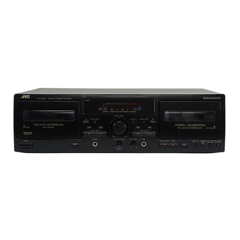
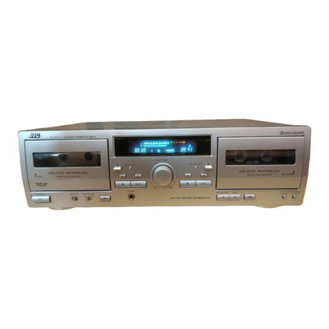
  9. JVC TD-W20A User manual

JVC TD-W20A User manual

JVC
TD-W20A/B/C/E/G/J/
36
we!
MODEL
-W20
A/B/C/E/
G/J/U
Contents
Safety
precaution
2.0
orb
be
ee
ees
Features
so.
set
Se
teas
PE
des
Saale
wm
Bra
es
Specifications.......
Names
of
Parts
and
Their
Functions..............
Location
of
Main
Parts
Removal
of
Main
Parts
Main
Adjustments...
.
Block
Diagram
......
2
Wiring
Connections:
<x
scsiau
sane
a
eis
Rohe
oes
1
3
Standard
Schematic
Diagram
of
TD-W20.........
14
3
P.W.
Board
and
Parts
List
...............000-
fe)
4
Exploded
View
of
Enclosure
Assembly
...........
2)
5
Exploded
View
of
Mechanism
Assembly
.........
22
6
DIMeNSIONS:
oes)
Si
ee
ale
eee
ee
28
8
Packing:
ak.
ohare
ede
Meatae
Be
end
&
2h
es
29
12
AccessorieéS
2.000.
ee
eee
Back
Cover
No.
4256
August
1985
TD-W20A/B/C/E/G/J/U
Safety
precaution
1.
The
design
of
this
product
contains
special
hardware.
Many
circuits
and
components
specially
for
safety
purposes.
.
For
continued
protection,
no
changes
should
be
made
to
the
original
design
unless
authorized
in
writing
by
the
manufacturer.
Replacement
parts
must
be
identical
to
those
used
in
the
original
circuits.
Service
should
be
per-
formed
by
qualified
personnel
only.
2.
Alterations
of
the
design
or
circuitry
of
the
product
should
not
be
made.
Any
design
alterations
or
additions
will
void
the
manufacturer’s
warranty
and
will
further
relieve
the
manufacturer
of
responsibility
for
personal
injury
or
property
damage
resulting
therefrom.
3.
Many
electrical
and
mechanical
parts
in
the
product
have
special
safety-related
characteristics.
These
charac-
teristics
are
often
not
evident
from
visual
inspection
nor
can
the
protection
afforded
by
then
necessarily
be
obtained
by
using
replacement
components
rated
for
higher
voltage,
wattage,
etc.
Replacement
parts
which
have
these
special
safety
characteristics
are
identified
in
the
parts
list
of
Service
manual.
Electrical
components
having
such
features
are
identified
by
(
Z\)
on
the
schematics
and
parts
list
in
Service
manual.
The
use
of
a
substitutue
replacement
which
does
not
have
the
same
safety
characterisitics
as
the
recommended
replacement
part
shown
in
the
parts
list
in
Service
manual
may
create
shock,
fire,
or
other
hazards.
4.
The
leads
in
the
products
are
routed
and
dressed
with
ties,
clamps,
tubings
barriers
and/or
the
like
to
be
separated
from
live
parts,
high
temperature
part,
mov-
ing
parts
and/or
sharp edges
for
the
prevention
of
elec-
tric
shock
and
fire
hazard.
When
service
is
required,
the
original
lead
routing
and
dress
should
be
observed,
and
they
should
be
confirmed
to
be
returned
to
normal,
after
re-assembling.
2
(No.
4256)
5,
Leakage
current
check
(Safety
for
electrical
shock
hazard)
After
re-assembling
the
product,
always
perform
an
isolation
check
on
the
exposed
metal
parts
of
the
Pro-
ducts
(antenna
terminals,
knobs,
metal
cabinet,
screw
heads,
earphone
jack,
contro!
shafts,
etc.)
to
be
sure
the
product
is
safe
to
operate
without
danger
of
electrical
shock.
Do
not
use
a
line
isolation
transformer
during
this
check.
e
Plug
the
AC
line
cord
directly
into
the
AC
outlet.
Us-
ing
a
‘Leakage
Current
Tester’,
measure
the
leakage
current
from
each
exposed
metal
part
of
the
cabinet,
particularly
any
exposed
metal
part
having
a
return
path
to
the
chassis,
to
a
known
good
earth
ground
(water
pipe,
etc,).
Any
leakage
current
must
not
ex-
ceed
0.5
mA
AC
(r.m.s.).
e
Alternate
check
method.
Plug
the
AC
line
cord
directly
into
the
AC
outlet.
Use
an
AC
voltmeter
having
1,000
ohms
per
volt
or
mroe
sesitivity
in
the
following
manner.
Connect
a
1500
2
10.W
resistor
paralleled
by
a
0.15
uF
AC-type
capaci-
tor
between
an
exposed
metal
part
and
a
known
good
earth
ground
(water
pipe,
etc.).
Measure
the
AC
voltage
across
the
resistor
with
the
AC
voltmeter.
Move
the
resistor
connection
to
each
exposed
metal
part,
particularly
any
exposed
metal
part
having
a
return
path
to
the
chassis,
and
measure
the
AC
volt-
age
across
the
resistor.
Now,
reverse
the
plug
in
the
AC
outlet
and
repeat
each
measurement.
Any
voltage
measured
musy
not
exceed
0.75
V
AC
(r.m.s.).
This
corresponds
to
0.5
mA
AC
(r.m.s.).
AC
VOLTMETER
(HAVING
1000
2/V
OR
MORE
SENSITIVITY)
O.1SpF
AC-
TYPE
1500.
1OW
PLACE
THIS
PROBE
ON
EACH
EXPOSED
METAL
PART
GOOO
EARTH
GROUND
Features
1.
Two
logic-control
deck
mechanisms
¢
Double-speed
dubbing
function
reduces
tape
editing
time
by
half.
.
Dolby*
B
&
C
noise
reduction
systems
e
Built-in
MPX
filter
.
2-color
6-LED
peak
level
indicator
.
Synchro-start
dubbing
.
Metal
tape
compatibility
.
Auto
tape
select
mechanism
(deck
A)
Nn
Oo
nh
Ww
Dolby
Laboratories
Licensing
Corporation.
Dolby
Laboratories
Licensing
Corporation.
Specifications
Type
:
Stereo
double
cassette
deck
Track
system
:
4-track,
2-channel
Tape
speed
:
1-7/8
inch/sec
(4.8
cm/sec)
Frequency
response
O
dB
recording
:
Metal
tape;
40—11,000
Hz
(+3
dB)
Chrome
tape;
40—8,000
Hz
(+3
dB)
Normal
tape;
40—8,000
Hz
(+3
dB)
—20dB
recording:
Metal
tape;
30—16,000
Hz
40—15,000
Hz
(+3
dB)
Chrome
tape;
30—16,000
Hz
40—15,000
Hz
(+3
dB)
Normal
tape;
30—15,000
Hz
40—14,000
Hz
(+3 dB)
:58dB
(S
=1kHz,
K3=3%,
N=A-
weighted,
Metal
tape)
The
S/N
is
improved
by
about
15
dB
at
500
Hz
and
by
max.
20dB
at
1kHz—10
kHz
with
Dolby
C
NR
on
and
improved
by
5
dB
at
1
kHz
and
by
10
dB
at
above
5
kHz
with
Dolby
BNR
on.
Improvement
of
MOL:
4dB
at
10
kHz
with
Dolby
C
NR
on
Wow
and
flutter
:
0.08
%
(WRMS)
0.20
%
(DIN
45
500)
Crosstalk
:
60
dB
(1
kHz)
Harmonic
distortion
:
K3
;0.5
%,
THD
;1.0%
(metal
tape,
1
kHz,
0
dB)
:
Deck
A;
METAPERM
head
for
play-
back
S/N
ratio
Heads
Deck
B;
METAPERM
head
for
record-
ing/play
back,
2-gap
ferrite
head
for
erasure
Noise
reduction
system
manufactured
under
license
from
“Doiby””
and
the
double-D
symbol
are
trademarks
of
TD-W20A/B/C/E/G/J/4
:
Electronic
governed
DC
motor
for
capstan/reel
x
1
(for
both
decks
A
and
B)
Motors
Fast
forward/
Rewind
time
Input
terminals
Mic
jack
x
2
:
Approx.
100
sec
with
C-60
cassette
:
Max.
sensitivity;
0.4
mV
(-68
dB
V)
Matching
impedance;
600
2
—
10kQ
:
Max.
input
level;
80
mV
imput
impedance;
50
kQ
Input
jack
x
2
Output
terminals
Output
jack
x
2.
:
Output
level;
300
mV
Output
impedance;
5
kQ
:
AC
240
V,
50/60
Hz
(TD-W20A)
AC
120
V,
60
Hz
(TD-W20C/J)
AC
240/220/115
V,
50/60
Hz
.
(TD-W20U)
Power
requirement
Power
consumption
:
With
power
on;
14
W
With
power
switch
standby;
0.8
W
Dimensions
:
17-1/8"
(135
mm)
W
4-11/16”
(118
mm)
H
9-1/8"
(230mm)
D
Weight
:
8.8
Ibs
(4.0
kg)
Accessories
:
Pin
plug
cord
x
2
Design
and
specifications
are
subject
to
change
without
notice.
(No.
4256)
3
TD-W20A/B/C/E/G/J/U
|
Names
of
Parts
and
Their
Functions
Qe)
POWER
switch
Cassette
holder
(deck
A)
Indicators
@
DUBBING
This
lights
to
indicate
that
the
unit
is
in
the
dub-
bing
mode.
®
HIGH
SPEED
This
lights
when
in
the
double-speed
dubbing
mode.
®
RECORDING
Lights
when
deck
B
is
in
the
recording
and
record
pause
mode.
MULTI
PEAK
INDICATOR
These
indicate
the
recording
level
during
recording
and
output
level
during
playback.
The
LED
indication
varies
with
the
signal
strength
during
recording
and
playback.
Cassette
holder
(deck
B)
TAPE
COUNTER
and
RESET
button
MIC
jacks
(L
[eft]
,
R
[ight]
)
Connect
microphones
(with
an
impedance
of
600
22
to
10
kQ)
to
these
jacks.
With
microphones
connected
to
these
jacks,
the
in-
put
to
the
LINE
IN
(REC)
terminals
is
cut
off
auto-
matically.
SYNCHRO
PLAY
button
Press
this
button
when
performing
synchro-dubbing.
Do
not
press
this
button
other
than
for
this
purpose.
(See
page
14.)
Cassette
operation
buttons
(deck
A)
>»
(play)
button:
Press
to
play
the
tape.
<<
(rewind)
button:
Press
to
rewind
the
tape.
p>
(fast
forward)
button:
Press
to
fast
forward
the
tape.
a
/4
(stop/eject)
button:
Press
to
stop
the
tape.
Pressing
this
button
after
the
tape
stops
opens
the
cassette
holder.
(The
tape
automatically
stops
when
it
reaches
the
end.)
4
(No.
4256)
@)
@
NR
SYSTEM
switches
The
left
switch
switches
on
and
off
the
noise
reduc-
tion
circuits
and
the
right
switch
selects
which
noise
reduction
system
(Dolby
B
NR
or
Dolby
C
NR)
is
to
be
used.
DUBBING
switch
Set
to
ON
(
mm
)
when
dubbing
from
deck
A
to
deck
B.
INPUT
LEVEL
control
Adjust
the
recording
level
with
this
control.
SPEED
switch
Used
to
switch
the
tape
speed
when
dubbing.
(
=
)
HIGH
:
For
double-speed
dubbing
(
a
)
NORM:
For
normal-speed
dubbing.
Moreover,
this
is
required
when
recording
from
the
LINE
IN
input
or
MIC
jacks.
Set
to
this
position
ex-
cept
during
double-speed
dubbing.
TAPE
switches
(deck
B)
When
recording
or
playing
back
on
deck
B,
select
the
correct
setting
according
to
the
type
of
tape
used.
Cassette
operation
buttons
(deck
B)
©
(record)
button:
Press
to
record
the
tape.
il
(pause)
button:
Press
to
temporarily
stop
the
tape
in
the
record
or
playback
mode.
Press
it
again
to
release
the”
pause
mode
and
restart
the
tape.
The
other
operations
of
the
buttons
are
the
same
as
those
of
deck
A.
TD-W20A/B/C/E/G/J/
Location
of
Main
Parts
Power
Cord
N.R.P.W.B
Power
Transformer
Pin
Jack
Rear
Panel
Deck
A
Main
P.W.B
Deck
B
Front
Panel
Power
Switch
Rec/P.
B.
Switch
Fig.
2
(No.
4256)
5
TD-W20A/B/C/E/G/J/U
Removal
of
Main
Parts
Enclosure
Section
»
Removal
of
Top
Cover
1.
Remove
six
screws
retaining
the
both
sides
of
the
top
cover.
2.
Remove
two
screws
retaining
the
back
side
of
the
top
cover.
=
Removal
of
Bottom
Cover
1.
Remove
three
screws
retaining
the
front
side
of
the
bottorn
cover.
2.
Remove
three
screws
retaining
the
rear
side
of
the
bottom
cover.
s
Removal
of
Rear
Panel
1.
Remove
three
screws
retaining
the
pin
jack
and
chassis
to
the
rear
panel.
2.
Remove
four
screws
retaining
the
Power
Trans.
3.
Remove
two
plastic
rivet
retaining
the
DIN
jack
to
from
the
rear
panel.
(TD-W20G)
=
Removal
of
Front
Panel
1.
Remove
three
screws
M,@
and
2)
retaining
the
Front
Panel.
2.
Remove
one
screw
8)
retaining
the
earth
wire
with
the
mechanism
ass’y.
3.
Pull
out
input
level
knobs.
2
Removal
of
Mechanism
Ass‘y
(Deck
B)
1.
Remove
the
counter
belt.
2.
Remove
four
screws
(4)
and
6)
retaining
the
Deck
B.
3.
Open
the
cassette
lid
by
depressing
the
STOP/
EJECT
button.
4.
Remove
the
cassette
holder
from
the
mechanism
ass’y
by
disengaging
its
fulcrums
on
the
both
sides.
(See
Fig.
5-B.)
Note:When
reassembling
the
cassette
holder,
set
the
holder
spring
in
the
right
foot
of
the
holder
prior
to
reassembly.
(Deck
A)
1.
Remove
four
screws
6)
and
®D
retaining
the
Deck
A.
2.
Open
the
cassette
lid
by
depressing
the
STOP/
EJECT
button.
3.
Remove
the
cassette
holder
from
the
mechanism
ass'y
by
disengaging
its
fulcrums
on
the
both
sides.
(See
Fig.
5-B.)
Note:When
reassembling
the
cassette
holder,
set
the
holder
spring
in
the
right
foot
of
the
holder
prior
to
reassembly.
#
LED
Indicator
Disengage
five
Pawls
a)
retaining
the
indicator
board
ass’y.
6
(No.
4256)
G@
41
“eS
DeckA/B
Cassette
Holder
Rear
View
Fig.
6
_|
TD-W20A/B/C/E/G/J
=
Removal
of
Power
Switch
(See
Fig.
5)
1.
Push
the
switch
knob
outward
to
remove
it.
2.
Push
the
switch
ass’y
in
the
direction
of
the
arrow
to
remove
it.
Note
:
When
reinstalling
the
switch
ass’‘y
:
1)
Set
the
switch
to
its
ON
position.
2)
Fix
it
as
shown
in
the
right
figure.
3)
Set
the
knob
to
the
switch.
Removal
figure
reinstement
figure
Fig.
7
Mechanical
parts
@
Rec./PB
head
(Deck
B)
PB
head
(Deck
A)
1)
Remove
two
screws
6)
for
the
button
assembly.
2)
Remove
a
screw
:
3)
Loosen
a
screw
for
adjustment.
@
Erase
head
(Deck
B)
Dumy
head
(Deck
A)
1)
Remove
a
screw
2)
Remove
a
screw
for
adjustment.
@
Pinch
roller
arm
assembly
1)
Remove
a
stopper
holding
its
assembly,
and
pull
it
off
from
the
shaft.
©@
Supply
reel
disc
assembly
1)
Pull
out
the
E
ring
67)
and
remove
its
disc
from
the
shaft.
@
Take-up
ree!
disc
1)
Pull
out
the
E
ring
and
remove
it
from
the
shaft.
@
Motor
1)
Remove
three
screws
2
and
fastening
the
FM
bracket.
(When
removing
the
FM
bracket
42),
remove
with
the
main
belt
and
the
RF
belt
44)
.)
2)
Remove
three
screws
45)
fastening
the
motor.
3)
Pull
out
the
motor
pulley
from
the
motor
shaft.
Fig.
9
Note:
Be
careful
not
to
stain
the
main
belt
and
RF
belt.
(When
assembling
the
motor
pulley,
adjust
the
pulley
position
as
next
figure.)
10.5mm
Fig.
10
MOTOR
Fig.
8
@
Flywheel
assembly
Pull
out
the
flywheel
from
the
capstan
metal.
(No.
4256)
7
‘D-W20A/B/C/E/G/J/U
Main
Adjustments
1.
Equipment
and
measuring
instruments
used
for
adjustments
1)
Electronic
voltmeter
2)
Audio
frequency
oscillator
(range;
50-20
kHz
and
output
0
dB
with
impedance
of
600
22)
3)
Attenuator
(impedance;
600
£2)
4)
Standard
tapes
for
REC/PB
Maxell
UD
—
Normal
(SF)
tape
—
TDKSA
—
Chrome
(SA)
tape
—or
equivalent
JVC
ME
—
Metal
tape
5)
Reference
tape
for
playback
(ve.
Test
Tape)
TMT6451
(or
VTT656A)
(for
tape
speed,
wow
flut-
VTT64
VTT73
ter
adj.)
4
(or
VTT724)
(for
playback
level)
9
(for
playback
frequency
response)
TMT7008
(14
kHz)
(for
head
azimuth
adj.)
2.
Mecha
Adjusting
motor
speed
Checking
wow
and
flutter
torque
Checking
fast
forward
torque
|
Checking
re-
wind
torque
nism
adjustment
proceder
6)
Resistor
600
Q
(for
attenuator
matching)
7)
Distortion
meter
(bandpass
filter)
8)
Torque
testing
cassette
gauge,
CGT-N
9)
Wow
flutter
meter
10)
Frequency
counter
*
Adjustment
1,
Connect
a
frequency
counter
to
the
LINE
OUT
terminals.
2.
Play
back
the
TMT6451
(or
VTT-
655A)
test
tape.
3.
Adjust
for
deck{A]:
Adjust
VRMO3
for
normal
speed
at
3000
Hz,
and
VRMO1
for
high
speed
at
6000
Hz.
Adjust
for
deck([B]:
Adjust
VRM04
for
normal!
speed
at
3000Hz,
and
VRMO2
for
high
speed
at
6000
Hz.
Connect
a
wow
and
flutter
meter
to
LINE
OUT
terminals.
Play
back
the
TMT6451
(or
VTT656A)
test
tape.
Check
to
see
if
the
reading
of
the
eter
is
within
0.08%
(WRMS)
m
.
Checking
Employ
a
torque
testing
cassette
tape
playback
for
the
checking,
or
remove
the
cas-
sette
cover
and
use
a
torque
gauge.
Remarks
For
adjusting
high
speed,
HI-SPEED
test
point
should
be
grounded.
Adjust
high
speed
after
perform
normal
speed.
If
the
reading
becomes
moving
value
even
if
confirming
to
the
standard,
a
re-claim
may
be
raised.
Repairs
are
necessary.
If
the
standard
torque
is
not
obtained,
replace
the
take-up
disk
assembly.
Measure
the
torque
in
the
fast
forward
mode
in
the
same
manner
as
in
the
above.
Measure
the
torque
in
the
rewind
mode
in
the
same
manner
as
in
the
above.
fis
8
(No.
4256)
Adjusting
Standard
point
value
Deck[A]:
|
Normal
speed:
Normal;
Deck
[Al;
VRMO3
3000
Hz
High;
Deck|B];
VRMO1
3000
Hz
Deck(B]:
|
High
speed:
Normal;
Deck|A|;
VRMO4
6000
Hz
High;
Deck({B/;
VRMO2
6000
Hz
0.08%
(WRMS)
0.2%
(DIN
45500)
35-75
gr-cm
More
than
70
gr-cm
More
than
70
gr-cm
If
the
standard
torque
is
not
obtained,
perform
the
following.
1.
Clean
the
capstan
belt,
the
idler
cir-
cumference,
the
motor
pulley,
the
take-up
reel
disk
circumference,
the
flywheel
circumference,
etc.
2.
Replace
the
belt
and
idler.
If
the
standard
torque
is
not
obtained,
clean
the
capstan
belt,
idler,
motor
pul-
ley,
flywheel
circumference,
rewinding
idler
circumference,
left
reel
disk
cir-
cumference,
etc.
|
TD-W20A/B/C/E/G/J;
Standard
value
Play
mode:
within
3
sec
FF/REW
mode:
within
5
sec
Adjusting
point
Checking
Play
back
the
tape.
In
playback
mode,
auto-stop
check
that
the
tape
run
stops
within
3
opeartion
sec
at
the
end
of
the
tape.
In
fastfor-
ward
or
rewind
mode,
check
that
the
tape
stops
within
5
sec
at
the
tape
end.
If
the
head
is
worn,
disconnected
or
exceedingly
magnetized
so
as
not
to
Screw
A
(left
side)
1.
Connect
an
electronic
voltmeter
to
the
LINE
OUT
terminals.
Adjusting
REC/PB
head
azimuth|
2.
Play
back
the
TMT
7008
test
tape.
each
provide
the
necessary
characteristics,
3.
Adjust
the
head
angle
with
the
|
Deck
replace
it
with
a
new
one.
screw
A
until
the
reading
of
the
peck
a
After
replacement,
the
head
position
electronic
voltmeter
becomes
maxi-
mum
for
both
channels.
4.
After
adjusting,
set
the
screw
with
screw
bond.
adjustment
as
well
as
the
playback
level
adjustment,
the
bias
current
adjust-
ment
and
the
recording
level
adjust-
ment
are
all
necessary.
If
the
output
difference
between
the
left
and
right
channels
exceeds
3—4dB,
the
head
is
defective.
Replace
it
with
a
new
one.
3.
Electrical
adjustments
location
@
Main
Amp
P.
W.
Board
(parts
assembly
side
view)
(Turning
in
the
direction
of
the
arrow
increases
the
level.)
VRIOL
INPUT
VR
u
“
o
?
é
=
o
z
S
S
Pa
S|
r
8
4
=
9
°
=
g
BIAS
F
Adj
<
-
a
z
Lao!
u
2
rs
3
=
6
be
4
a o
=
a
Qs
rec
cever
vate
C))
BIAS
Ad.
|
caterer
ene
era
|
Rch
Lich
VRMO3
VRMO4
[J
SPEED
Ads
NORM
i)
|
Radi
To
RIO,
P.B
EQ
|
ras
F203
f
i
oo
HIGH
_
REC
--
PB
VRMOI
VRM02
HISPEED
CHECK
G3
SPEED
Adj
00
Reh
(A)
P.
8.
GAIN
Ag)
Fig.
11
(No.
4256)
9
‘D-W20A/B/C/E/G/J/U
4,
Electrical
circuit
adjustment
procedure
Perform
the
tape
transport
checks
and
head
azimuth
adjustment
before
following
checks
and
adjustments.
Adjustment
should
be
performed
in
the
order
of
alignment
steps.
In
the
steps
marked
with
an
asterisk
(*),
adjustment
should
be
performed
after
replacing
the
heads.
Perform
this
adjustment
with
the
NR
switch
set
to
OFF.
Check
and
Adjustment
Signal
input:
LINE
IN
1
kHz,
Cal.
—40
dB
+5.7dB+1dB
DOLBY
B
(Rec)
Sel
[Cal
evel:
400
Hz,
68s
(BIAS,
CUT)
|Output
terminal:
NR.
TP
DOLBY
c
P
Adjusting
Standard
Step
Item
Adjustment
point
value
Remarks
*2
|Confirming
|
Play
back
VTT644
(or
VTT724),
then
|DeckA
When
the
head
is
replaced,
adjust
confirm
that
the
level
at
LINE
OUT
is
[L:R153,R154/Bi|-8+
1.5dB
(Al—7dBs+1.5dB,{B]—8dBs+1.5dB
alerlee
eC
|
playback
gain
playback
gain
level.
Deck
A
L:R153
cut
by
+1dB
R154
cut
by
—1dB
R:R253
cut
by
+1dB
R254
cut
by
—1dB
Deck
B
L:
R122
cut
by
+1dB
R125
cut
by
—1dB
R:R222
cut
by
+1dB
R225
cut
by
—1dB
bias
frequency
10
(No..4256)
C925,Lead
through
a
1.2
MQQ
resistor,
then
adjust
L901
so
that
the
counter
reads
95
kHz.
*3.
|
Playback
Deck
A:
Play
back
VTT739,
then
con-
B72
cut
by
—1dB
frequency
firm
that
the
level
of
1
kHz
and
IL:
B73
cut
by
—2dB
response
10
kHz
signals
is
0.5
+
2
dB.
R:VR203
|
Deck
B:
B75
cut
by
—1dB
Deck
B:
Before
adjustment,
disconnect
|DeckB
0+2dB
B76
cut
by
—2dB
B72,
B73
(L-ch)
and
B75,
B76
L:872,873
(R-ch)
so
that
the
outputs
of
1
KHz
|L:B75,B76
and
10
kHz
signals
are
flat.
a
Adjusting
Connect
the
frequency
counter
to
the
|
L901
95
kHz
METAL
Position
+
10%
=
kHz
outputs
satisfy
the
standard
values
with
respect
to
1
kHz
output.
Response
(dB)
a
Decrease
in
high
frequencies
QO
50
Hz
1
kHz
ode
Increase
in
high
frequencies
Low
bias
current
Appropriate
bias
current
High
bias
current
12.5
kHz
Frequencies
*5
|Recording
|
1)
NR
switch:
OFF
For
With
respect
|
CrO2
frequency
2)
Record
a
1kHz
signal
at
an
input
;
Normal
to
1
kHz
50Hz
Q+3dB
response
reference
level
of
—20dB,
then
|
tape:
reference:
12.5kHz
O+4dB
record
50
Hz
and
12.5
kHz
signals
|}
L:
VR102;}
At
50
Hz,
Metal
and
play
them
back.
At
this
time,
|
R:VR202}
0+3
dB;
50Hz
0+3dB
adjust
VR102
and
VR202
so
that
At
12.5
kHz,
12.5kHz+1+4dB
the
deviation
of
50Hz
and
12.5
0+3dB
Recording
gain
Adjustment
1)
Apply
a
1kHz
signal
to
the
LINE
IN
terminals,
record
a
1kHz
signal
at
O
dB
input
for
both
L
and
R
channels
on
a
normal
tape.
2)
Play
back
the
recorded
part,
and
adjust
the
recording
level
controls
so
that
LINE
OUT
terminal
level
becomes
—8
dBs
with
peak
level
indicator
reading
O.
Then
adjust
VR104
and
VR204
so
that
LINE
OUT
terminal
level
becomes
—8
dBs.
Adjusting
For
Normal
R303
R301
R:R400
R402
“R403
R404
—8
+
2.5
dB
[
Standard
value
TD-W20A/B/C/E/G/.
Perform
the
adjustment
using
a
nor-
mal
tape.
Level
difference
between
recording
and
playback
for
VX/
CrO,
and
metal
tapes
should
be
less
than
1.5
dB,
and
that
between
left
and
right
channels
should
also
be
less
than
1
dB.
L:R300
cut
by
+1.4dB
R302
cut
by
+0.5dB
R303
cut
by
—1.3dB
R301
cut
by
—2.5dB
R:R400
cut
by
+1.4dB
R402
cut
by
+0.5dB
R403
cut
by
—1.3dB
R401
cut
by
—2.5dB
Be
sure
to
perform
this
checking
following
bias
current
and
record-
ing
level
checking.
Checking
Record
a
1kHz,
—8dB
signal
to
Normal
tape:
record/
LINE
IN
terminals
and
perform
Less
than
2%
playback
recording
with
the
peak
level
indi-
CrO,
tape:
distortion
cator
reading
0.
Less
than
3%
2)
Play
back
the
recorded
part.
Check
Metal
tape:
the
output
with
a
distortion
meter
Less
than
2%
to
see
if
the
value
conforms
to
the
(THD)
standard
value.
Checking
1)
Record
a
1
kHz,
0
dB
signal.
Stop
Normal,
CrO2
signal
to
nosie
the
input
by
disconnecting
from
the
&
Metal
tapes:
ratio
in
terminal
to
perform
non-signal
More
than
recording/
recording.
42
dB
playback
2)
Play
back
the
recorded
part.
Mea-
Checking
erasing
coefficient
sure
the
O
dB
recording
output
and
the
non-signal
recording
output
for
comparison
using
an
electronic
volt-
meter.
Check
to
see
if
the
value.
con-
forms
to
the
standard
value.
Apply
a
1
kHz
signal
to
the
LINE
IN
terminals.
Adjust
the
recording
level
controls
until
the
peak
level
indicator
reads
O
dB.
2)
Perform
recording
with
the
signal
enhanced
by
20
dB.
3)
Erase
a
part
of
the
recording.
4)
Measure
the
output
difference
be-
tween
the
erased
part
and
non-
erased
part
to
compare
with
an
electronic
voltmeter.
More
than
65
dB
HA12088
Apply
an
input
level
to
LINE
IN
terminals
with
the
recording
level
controls
set
to
maximum
so
that
the
peak
level
indicator
reads
O
dB.
For
the
measurement
using
a
metal
tape,
connect
a
band
pass
filter
be-
tween
the
deck
and
the
electronic
voltmeter.
Tape
deck
(recording,
Input
(1
kHz0
VU
+20
dB)
erasing)
Electronic
voltmeter
(1
kHz)
Band
pass
Filter
(No.
4256)
11
*D-W20A/B/C/E/G/J/U
Block
Diagram
goza
9010
ig—-4¢
“ye
&
vy
(At
A+
(12)
Sos
YOLVINOAY
0260
NIG
YO4
LNO
J3a¥
(1)
LNG
Sd
Q)
yu)
4NQ
934
2)
aa
ino
3NIT
©)
z0€F
>
W3LSAS
YN
430
NO
@
3AB10G
MSYN
NIGd
NID3Y
q)
a)
YN
9-8
AGIOG)
1089]
(4)LNO
@d
Go)
(dy)
(4)
MS
d/¥
NiGd
NI
234
@-e)—()
AVId
938
is
th
39,
103738
3dv1
I
KQ)
MS
03
NiVO
Sd?
1901'SOLO
MS
VHIaN
fg]
[>
EOLUAT
19373S
3dv1
[8]
Wee
9-15
‘G-1S
&)
dwv
334
193975S
3dvV1
(8)
lg
SMBS
S-1S
WYON
ot
(Aza
+
NOO
Qa
430
m
ONISENG
=
€-1S
I-1S
ZC
&
OV3H
ad
[¥]
03
QV3H
d/y
[a
1-2S
AW1d
9
Geof?
D3u
x
K5@)
OD
dv
NIQL.
lolvof~
Nid
of
pe
NI
ANID
L-€r
Fig.
13
12
(No.
4256)
Wiring
Connections
1
|
2
eo
:
:
{op}
ioe)
i<e)
Head
Amp
Level
Meter
Board
Ass’y
Board
—
Deck.B=—
—
Deck.A=—
‘
4
R/P
Head
E.Head
P.B
Head
B
|
|
|
—
1
Main
Amp
‘
Board
Ass’y
|
C
|
ee
Power
SW
|
Board
Ass
y
on
|
|
D
|
|
iG
|
|
ro
_|
=
Loe
.
TD-W20A/B/C/
J
|
SS
-Tp-W20E/6
E
Color
code
are
shown
below
F
a
Pause
SW
G
:
oe
NR
Board
Ass’y
Fig.
14
(No.
4256)
13
TD-W20A/B/C/E/G/J/U
TD-W20A/B/C/E/G/J/U
Standard
Schematic
Diagram
of
TD-W20
1
2
L
3
-¢]
4
|
5
fe
6
i
8
9
10
—
sI
T5642-VOI
s
2
1
ere
SHI
NR
S1-2
OOLBY
B¢
OF
F=—eON
B<——C
vR901
SOk(A)
Qvzs017-Vvor
RNG
22k
J3_
PIN
JACK
EMNOOTV-402A
(BIN
AMP]
R516
67k
'
=|-
E
;
is
Vico
RAIOI
al
a
yok
CAI91
El
2
tT
aa
|
ent
<a
?
bd
1
10/25
Se}
ie
o
ba
2
i
3
a
al
S|
°
on
=| Z|
Se
Sk
=f
3
ue
a
oo
8
aan
q|
low
oS}
3}
Oo
—~2
¥
Se
S2
REC/PB
SW
REC<—ePB
QS$9201-005R
L501,
L601
VQZ0025
-001S
(Bl
R/P
HEAD
VGHO421-014
GL-9PA72
0101,102,
103,
0201,
202,203,
GL-9HY792
0104
105,106,
0204,
205
206,
GL-9PR4
0920
GL-9HY94
0921,
922,
C945
10/25
C440
90.22
/
50
ov
+
C44)
ov
R460
18k
ed
i
a
100
1/2W
R36
U
13e°
22725
cn7
470P
¥A
1/6W
(@)
Pe
Head
VGHO421-016
R317
100k
|
|
L
weil
|
02
Zs
a
zs
on
Ee
—————
5
ee
[
S3
POWER
Sw
=
pratian
z
280882
(P,Q)
|
QSP0219-061
f
es
=
os
113V
re
WN
ON=—=OFF
ze
gs
ge
R970)
Qs
ey,
22
@
(|
O90
A
|
ma
i
-
:
8
=
3
~~
eg
w
'
$
f\901
:
&
:
POWER
CORD
y
*
U
-
QMP1200-200
|
g
be
2,
TO
-W20
C/J
a
>
2 a
a
aa
2
a
ERASE
HEAD
83
L
ay
ae
a
i
VGHO212+104
wiz
%1
TO-w20
C/J
Zan
aoa
aec
P—
4]
>>
POWER
CORD
«@
o
QMP
2560-200
&
=z
0
—
ene
=
Gaz
R2
MAIN
P.W.B
VMWI654
A
ena
NOTES
UNLESS
OTHERWISE
SPECIFIED
ALL
RESISTORS
ARE
1/6W,+5*/e,
CARBON
RESISTOR.
ALL
CAPACITORS
ARE
SOV.
CERAMIC
OR
MYLAR
CAPACITOR.
ALL
RESISTANCES
VALUES
ARE
IN
OHM(N)
ALL
CAPACITANCE
VALUES
ARE
IN
yF
(P=
107%).
[2SC2001(L.K)
|
7SC1684(R,S)
ale
=
N
oy
c
Q103,
107,
112,
501,
502,
Q902,909
910,911,913,
914,
Q921,
926
931,
933,
8
GMP9017-ooBBS
-—P~
Red
line
shows
the
signal
at
recording.
|
—P-—
Blue
line
shows
the
signal
at
playback.
|
POWER
CORD
ALL
E.CAPACITORS
ARE
SHOWN
IN
THE
FROM
OF
CAPACITANCE
(yr)
/
RATEO
@
A/E/G
QMP
2560-200
VOLTAGE
(V)
aes
MECHA
Gece
ae0r
sor
$08
912,925
930.
i i
UNFLAMABLE
CARBON
RESISTOR.
nd
[asxzee
(Gay
foror.10s.106.
[p-w20_
4
AIBIEIG_
|
+B
circuits.
120%.
LOW
LEAK
CURRENT
ELECTROLYTIC
CAPACITOR.
z
t
of
~
xz
g
Inscisas
(€,0)
[oar]
<
M901
<=>
w
VOLTAGES
ARE
OC
MEASURED
WITH
A
DIGITAL
VOLT
METER
WITHOUT
Zo
YS
ZO
ia
a8
ascisec
FY
fans
~~]
INPUT
SIGNAL
aE
<2
94
}OTOR
So
26
pscraie
5)
AN
Parts
are
safety
assurance
parts.
MODE
:
OUBBING
,
TAPE
CrO2/METAL,
G)
METAL
,
NR:OFF)
as
rs
ss
MMA~6B2LWF
KX
ve
£4
WM
Ar
6B2LWFKX
1090S
3
G
(Mol
UBBING
,
@
croz
a)
€
2
ae
et
*e
[iss2s4_[0901,902,903,904
905,906
907
|
When
replacing
those
parts,
make
sure
to
use
the
specified
one.
Fig.
15
14
(No.
4256)
P.
W.
Board
and
Parts
List
(Pattern
Side)
1
|
2
|
3
|
4
|
5
|
10
|
a
Fig.
16
ole
Ne
.
O89
OS
SYOE:
The
Cr22
ai4g
=
R917
aios['
[oT
|hss0
ob
©
Nb
=
Main
Amp
P.W.
8B.
MIC
P.W.B.
Level
Meter
P.
W.
B.
Power
SW
P.W.B.
NR
P.W.B.
Head
Amp
P.W.B.
Parts
Side
(No.
4256)
15
TD-W20A/B/C/E/G/J/U
TD-W20A/B/C/E/G/J/U
TD-W20A/B/C/E/G/J/U
la]
REF.
NO
PARTS
NO,
PARTS
NAME
REMARKS
REF.
NO
PARTS
NO.
PARTS
NAME
REMARKS
QRD149J-102S
QRD149J-12158
QRD149J-2R2S8
QRD149J-SR6S
QRD149J-8R2S
QRD149J-8205
Q@RD161J-101
2S5C01845(E-U)
2$C2001(L-K)
25D882(Q-P)
2SK246(GR)IE2
RESISTOR
IC801
HA12088NT
A
L502
,L602
|
VQ@Z0013-001S
FILTER
2
IR2E27A
1
L501
,L601
|
VQZ0025-001S
2
UPC1228H
2
QRD129J-101
RESISTOR
2
Q@M101-QM201|
2SA733AC(P-K)
8
QRD141J-391S
1
7Q901
QRD143N-222S
1
QRD143J-2235
1
QRD144J-1R0S
2
2$C1318(R-S)
1
QRD144J-121S
2
2S5C1344(E-F)
2
Q@RD1443-183S
2
2$C1684(R-S)
19
2
QRD144J3-2735S
2
Q@RD144J-332S
2
QRD144J5-3935S
2
QRD144J-6825S
2
QRD144J3-8225
2
2
2
2
4
1
1
4
13
QRD161J-102
CARBON
RESISTOR
GL-9HY792
GL-9HY94
GL-9PR4
GL-9PR72
RD1I2EC(B2)
1SS254T-77
11£1-TB2
QVP4A0B-104
QVZ1802-472
QVZ3512-103
QV2Z3512-203
QVZ5017-V0O1
QMV5004-003
QMV5004-004
QMV5004-006
QMV5004-007
QMV5005-006
VMZ0028-008
QSP0219-061
Q$$2325-205
Q@S$9201-005R
QST5642-VOl
VQH1008-006
VQP0001-102S
VQP0001-1835
Q@RD161J-104
QRD161J-105
CARBON
RESISTOR
14
POWER
SWITCH
TD-W20U
V.SELECT
REC/PB
SELECT
CARBON
RESISTOR
es
CARBON
RESISTOR
QRD161J-122
VQP0001-562S
16
(No.
4256)
TD-W20A/B/C/E/G/J
A
REF.
NO
PARTS
NO.
PARTS
NAME
REMARKS
R319
-R419
R115
,-R215
2R416
QRD161J-123
CARBON
RESISTOR
5
CARBON
RESISTOR
QRD161J-124
2
C
RESISTOR
2
2
2
5
QRD161J-125
QRD161J-151
CARBON
RESISTOR
QRD161J3-152
CARBON
RESISTOR
RM104-RM204|
QRD161J-153
CARBON
RESISTOR
R300
-R400
R936
R304
,-R343
|
QRD161J-154
CARBON
RESISTOR
4
R404
-,R443
R146
-R246
|
QRD161J-155
CARBON
RESISTOR
2
Fist
7R250
|
QRD161J-182
CARBON
RESISTOR
R508
-R608
CARBON
RESISTOR
CARBON
RESISTOR
QRD161J-203
QRD161J-222
RB00
R114
-R506
R606
RA106,-RA206
QRD161J-223
CARBON
QRD161J-224
CARBON
RA104-RA204
RM101,RM201
:
Ree
7R226
|
QRD161J-272
CARBON
RESISTOR
CARBON
RESISTOR
CARBON
RESISTOR
12
R322
,R422
|
QRD161J3-331
RA102-RA202|
QRD161J3-332
R102
-R107
R151
-R173
R202
cR207
|
R251
-R273
R510
-R610
R311
-R341
R411
-R441
R932
RA901-R901
R910
-R913
R142
-R172
R242
,R272
R152
-Reo2
Ri41
-R144
R191
-R241
R244
-R291
R301
-R401
R507
-R514
7R614
QRD161J3-333
CARBON
RESISTOR
5
QRD161J-334
CARBON
RESISTOR
4
QRD161J-392
CARBON
RESISTOR
4
CARBON
RESISTOR
2
CARBON
RESISTOR
15
QRD161J-471
QRD161J5-472
RESISTOR
QRD161J-473
(No.
4256)
17
+D-W20A/B/C/E/G/J/U
a)
REF.
NO
|
PARTS
NO.
PARTS
NAME
REMARKS
ory.
R402
-R413
R119
-R219
|
QRD161J-512
CARBON
RESISTOR
2
R170
-R270
|
Q@RD161J-562
CARBON
RESISTOR
3
R935
RA105,-RA205|
QRD161J-563
CARBON
RESISTOR
4
RM105-RM205
R318
-R418
|
QRD161J-564
CARBON
RESISTOR
2
R904
-R915
|
QRD161Jd-6R8
CARBON
RESISTOR
3
R937
R120
,R220
|
Q@RD161J-622
C
RESISTOR
2
R143
,R174
|
QRD161J-682
CARBON
RESISTOR
9
R243
-R274
R303
-R403
R509
-R609
:
R950
-
_
;
R307
-R4O7
|
QRD161J-683
CARBON
RESISTOR
6
R512
,R612
R912
-R941
R117
-R118
|
QRD161J-684
CARBON
RESISTOR
6
R245
/R217
|
R218
-R245
R305
-R405
|
Q@RD161J-823
CARBON
RESISTOR
2
R203
25C01684(R-S)
TRANSISTOR
)
C939
-C940
|
QCF11HP-103
C
CAPACITOR
2
C106
-C119
|
Q@CS11HJ-151
C.CAPACITOR
7
C206
Cag
|
C301
444
C342:
C442)
GCSITHI=181 C.CAPACITOR
2
C104
+C204
|
@CS11HJ-221
|C.
CAPACITOR
4
€320
7C420
r
|
C343
-C443
|-QCS11HJ-331
C.CAPACITOR
2
C103
-C117
|
@CS11HJ-471
C.CAPACITOR
tp
C203
76217
C101
C201
|
@CS11HJ-561
C
CAPACITOR
|
4
C300
C400
y
C312
-C412
|
@CS32HJ-151ZV
|C
CAPACITOR
2
C102
-C202
|
QCY41HK-102
C.CAPACITOR
2
C301
-C401
|
QCY41HK-332
C.CAPACITOR
,)
C118
,C218
|
QEBSI1EM-475M
|E.CAPACITOR
2
€105
-C205
|
QEB61EM-475Z2M
(LLC
E
CAPACITOR
2
C306
-C406
|
QEB61HM-3342M.
ILLC
E
CAPACITOR
2
AIC935
@ETA1CM-108VM
|E
CAPACITOR
1
C800
QETA1CM-227M
JE
CAPACITOR
1
C901
QETC1CM-2277M
|E.CAPACITOR
{
C915
QET41AR-107
E
CAPACITOR
1
C107
-C120
|
QET41AR-476
E
CAPACITOR
4
C207
-C220
C80z
QET41AR-477
E
CAPACITOR
1
C934
QET41CR-108
EE
CAPACITOR
1
C905
QET41CR~227
E
CAPACITOR
1
AIC937
QET41CR~477
E
CAPACITOR
1
CA101-CA201}
QET41ER-106
E
CAPACITOR
19
CA901-C109
C122
,C209
18
(No.
4256)
TD-W20A/B/C/E/G/J/
C222
-C504
C515
-C516
C604
-C615
C616
-C804
C903
-C908
C910
-C928
C945
C936
QET41ER-108
E
CAPACITOR
1
C341
7C441
|
QET41ER-226
E
CAPACITOR
2
C938
QET41ER-228
E
CAPACITOR
1
CA102,-CA202|
QET41HR-105
E.CAPACITOR
19
C307
#0407
C500
,C501
C506
-C600
C601
-C606
C801
C902
6906
-0907
C90S
+C946
C947
-C949
{e340
6440
QET41HR-224
E.CAPACITOR
2
C308
-C408
|
QET41HR-335
E.CAPACITOR
2
6920
QET41HR-475
E
CAPACITOR
it
C509
-C514
|
QET61HR-2252M
|E.CAPACITOR
4
C609
-C614
_|c508
-C513
6
E.CAPACITOR
—
4
C608
C613
C502
,C602
|
@FN41HJ-152
M.CAPACITOR
2
C302
-C402
|
QFN41HJ-272
M.CAPACITOR
2
C503
-C603
|
QFN41HJ-332
M.CAPACITOR
2
C926
QEN41HJ-472
M.
CAPACITOR
1
C121
-C221
|
QFN41HJ-562
M.CAPACITOR
4
C309
-C409
6925
QFPB2AJ-103
P.P.CAPACITOR
1
C108
-C125
|
QFV41HJ-103
TF
CAPACITOR
8
C208
-C225
C505
C511
|
6605
-C611
C507
-C510
|
QFV41HJ-183
M.
CAPACITOR
de
C607
-C610
|c927
QFV41HJ-223
M.CAPACITOR
1
C512
,C6l12
|
QFV41HJ-823
TF
CAPACITOR
2
6310
-C410
|
QFV71HJ-1232M
|TF
CAPACITOR
2
J3
EMNOOTV-402A
|PIN
JACK
1
J4
QMC9014-008
DIN
SOCKET
TD-W20G
1
lJ4
AD
QMS6313-017
JACK
MIC
2
F11
VMZ0043-001S
FUSE
CLAMP
TD-W20A/B/E/G
FUSE
2
TP1
VMZ0015-001
PIN
1
(No.
4256)
19
TD-W20A/B/C/E/G/J/U
20
(No.
4256)

This manual suits for next models

6

Other JVC Cassette Player manuals

JVC PC-Y777 B User manual

JVC

JVC PC-Y777 B User manual

JVC HR-XVC22UC User manual

JVC

JVC HR-XVC22UC User manual

JVC RC-M90JW/W User manual

JVC

JVC RC-M90JW/W User manual

JVC RC-565 JW User manual

JVC

JVC RC-565 JW User manual

JVC HR-J271MS User manual

JVC

JVC HR-J271MS User manual

JVC RC-250L User manual

JVC

JVC RC-250L User manual

JVC TD-W103A User manual

JVC

JVC TD-W103A User manual

JVC RC-636L User manual

JVC

JVC RC-636L User manual

JVC TD-W354B User manual

JVC

JVC TD-W354B User manual

JVC RC-W410 User manual

JVC

JVC RC-W410 User manual

JVC RC-545L User manual

JVC

JVC RC-545L User manual

JVC CX-F5K User manual

JVC

JVC CX-F5K User manual

JVC HR-VP680U User manual

JVC

JVC HR-VP680U User manual

JVC DD-9 A User manual

JVC

JVC DD-9 A User manual

JVC HR-C3 User manual

JVC

JVC HR-C3 User manual

JVC KD-A77 A User manual

JVC

JVC KD-A77 A User manual

JVC HR-XVC1U User manual

JVC

JVC HR-XVC1U User manual

JVC TD-W254 B User manual

JVC

JVC TD-W254 B User manual

JVC RC-550L User manual

JVC

JVC RC-550L User manual

JVC CD-1920 User manual

JVC

JVC CD-1920 User manual

JVC RC-M90JW User manual

JVC

JVC RC-M90JW User manual

JVC RC-660 L User manual

JVC

JVC RC-660 L User manual

JVC CD-1770 User manual

JVC

JVC CD-1770 User manual

JVC BIPHONIC RC-838W User manual

JVC

JVC BIPHONIC RC-838W User manual

Popular Cassette Player manuals by other brands

Aiwa NSX-DP85 Service manual

Aiwa

Aiwa NSX-DP85 Service manual

Sony Walkman WM-EX372 Service manual

Sony

Sony Walkman WM-EX372 Service manual

Philips AQ6404 user guide

Philips

Philips AQ6404 user guide

Sony Walkman WM-EX621 Service manual

Sony

Sony Walkman WM-EX621 Service manual

Sony EV-S350 operating instructions

Sony

Sony EV-S350 operating instructions

Philips AW 7760 Instructions for use

Philips

Philips AW 7760 Instructions for use

Onkyo TA-R33 Service manual

Onkyo

Onkyo TA-R33 Service manual

Sony Walkman WM-FX271 Service manual

Sony

Sony Walkman WM-FX271 Service manual

Sony TC-WR545 Primary operating instructions

Sony

Sony TC-WR545 Primary operating instructions

Pioneer CT-95 operating instructions

Pioneer

Pioneer CT-95 operating instructions

Sony WM-PA1 Service manual

Sony

Sony WM-PA1 Service manual

Sony WM-10II Service manual

Sony

Sony WM-10II Service manual

Yamaha MT3X Operation manual

Yamaha

Yamaha MT3X Operation manual

Sanyo CWM-550 Service manual

Sanyo

Sanyo CWM-550 Service manual

Technics RS-TR165 Service manual

Technics

Technics RS-TR165 Service manual

Philips AQ6546 user manual

Philips

Philips AQ6546 user manual

Yamaha K-220 owner's manual

Yamaha

Yamaha K-220 owner's manual

Panasonic RXFT530 - RADIO/DUAL CASS-LOW operating instructions

Panasonic

Panasonic RXFT530 - RADIO/DUAL CASS-LOW operating instructions

manuals.online logo
manuals.online logoBrands
  • About & Mission
  • Contact us
  • Privacy Policy
  • Terms and Conditions

Copyright 2025 Manuals.Online. All Rights Reserved.