– 2 –
TABLE OF CONTENTS
Servicing Notes ............................................................... 2
1. GENERAL
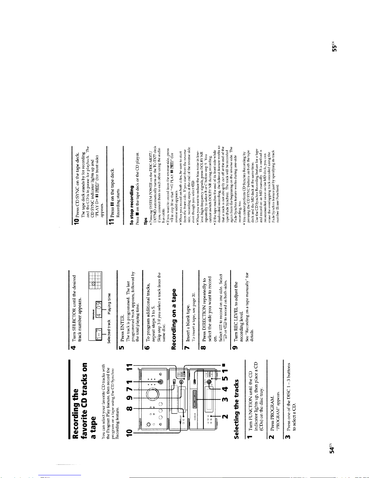
Playing a Tape ................................................................ 3
Recording on a Tape Manually....................................... 4
Recording the favorite CD Tracks on a Tape.................. 5
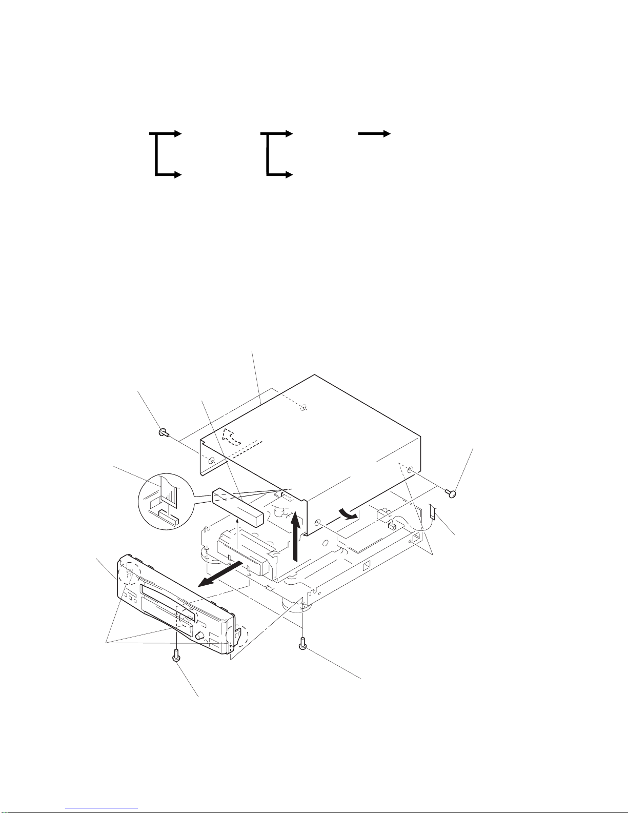
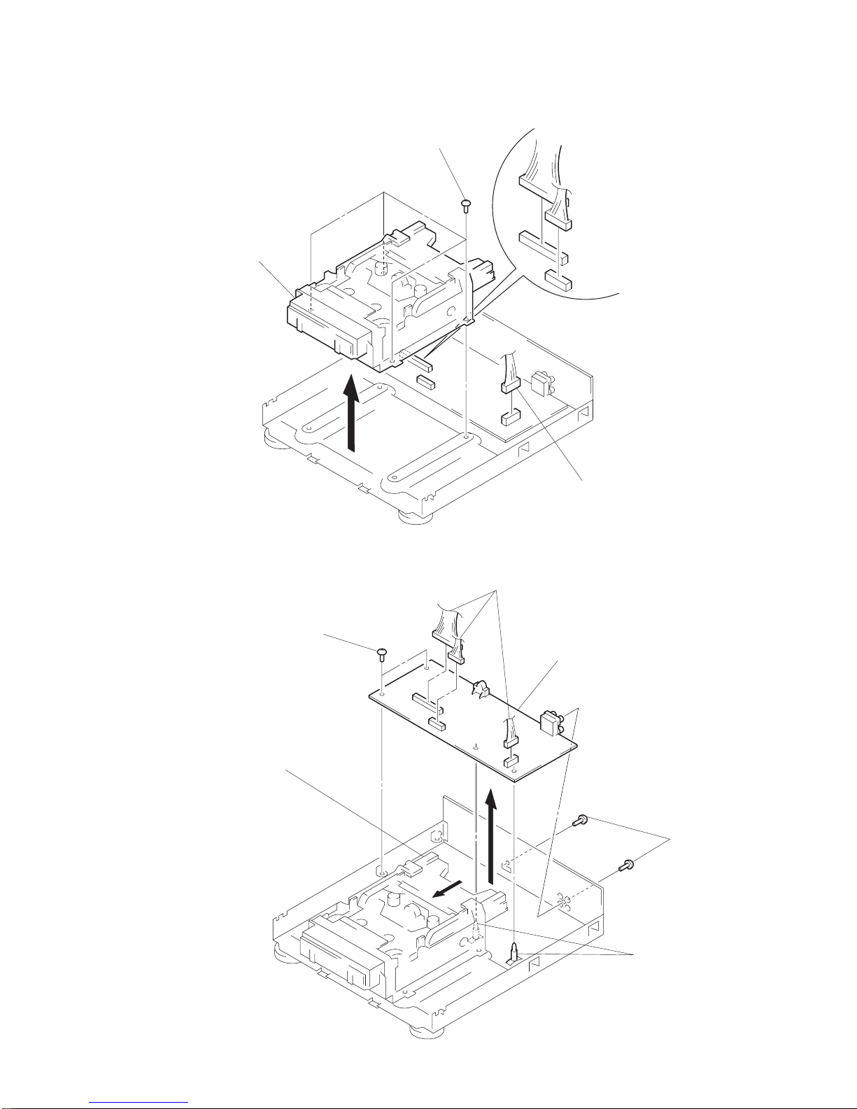
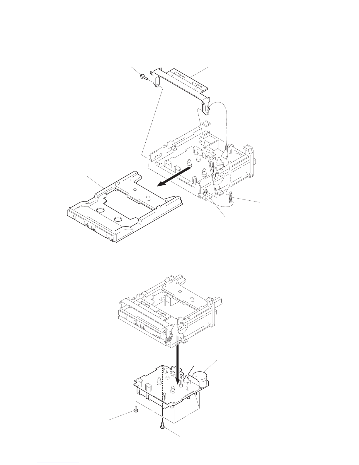
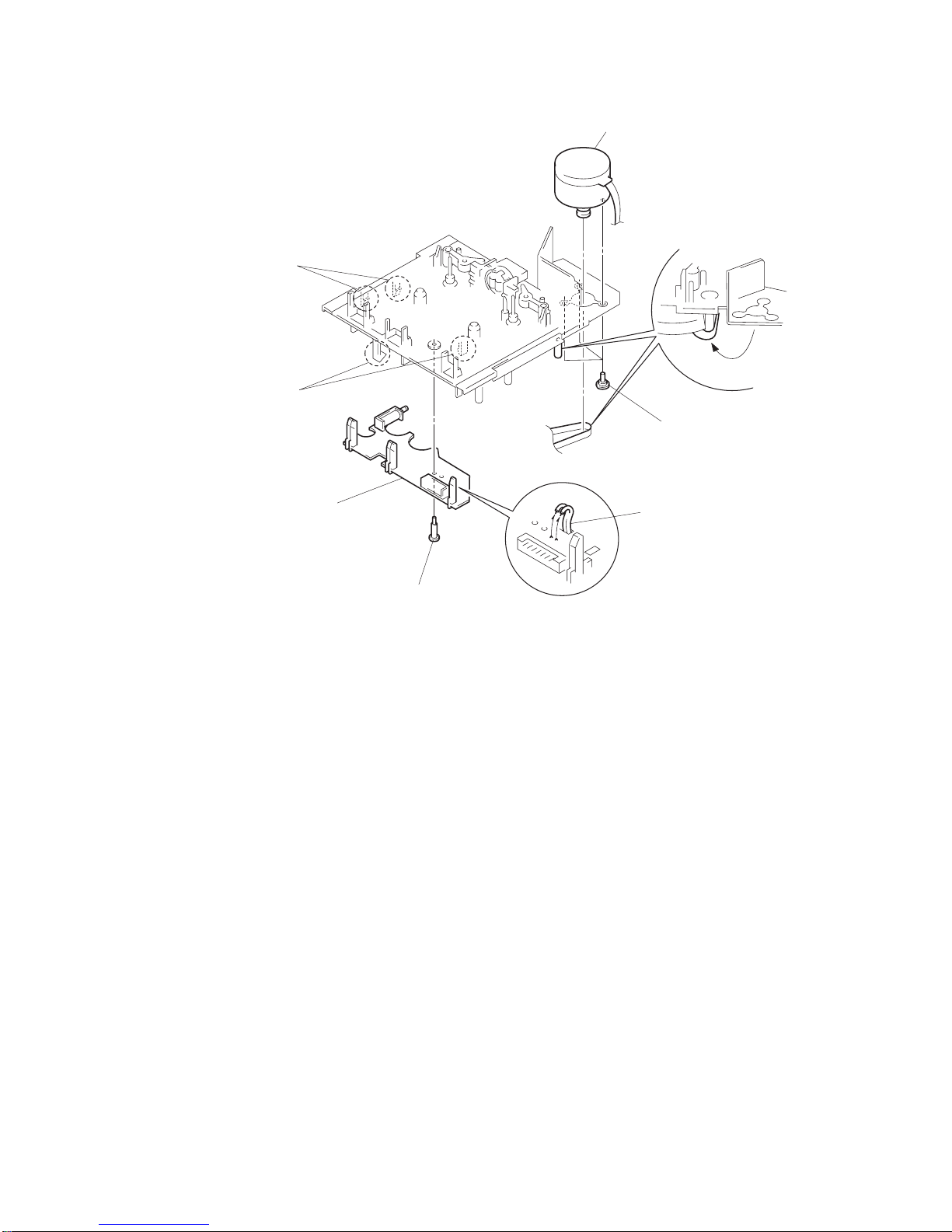
2. DISASSEMBLY ........................................................ 6
3. MECHANICAL ADJUSTMENTS ...................... 10
4. ELECTRICAL ADJUSTMENTS ........................ 10
5. DIAGRAMS
5-1. Printed Wiring Boards .................................................... 15
5-2. Schematic Diagram ........................................................ 19
5-3. IC Pin Function .............................................................. 25
6. EXPLODED VIEWS ............................................... 27
7. ELECTRICAL PARTS LIST............................... 32
SERVICING NOTES
How to operate with a single unit.
Normally, this set is not operated with its own.
The exclusive jig (J-2501-078-A) and service box (PFJ-1) are nec-
essary to operate the set with a single unit.
Turn the power set of the service box ON. Then press the
ENTER/NEXT button and SLEEP button at the same time to
turn the power on.
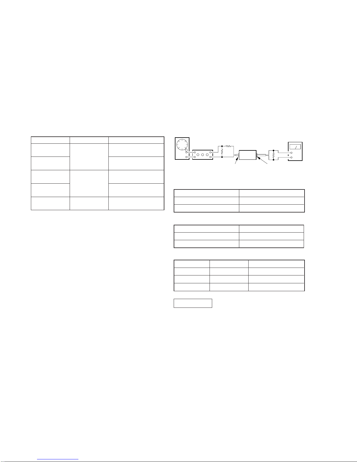
Connection:
• KEY/FL tube/LED check mode.
To enter KEY/FL tube/LED check mode, press the ENTER/NEXT
and REC buttons at the same time.
Under mode, every time when press any key or turn
MULTI CONTROLLER knob, change to next situation.
1All LED indicators light on
2All FL tube indicators light on
3A part of FL tube light on mode 1. (Indicated ST-SEG)
4A part of FL tube light on mode 2. (Indicated RDS-SEG)
5KEY check mode
Note:
1) All LED light on mode is kept, when buttons which is pressed
to enter all LED light on mode, release same time.
When release them separate timing, it is moved to next All
LED light on mode.
2) After all LED light on mode, light on point remove one by one,
when any button pressed or MULTI CONTROLLER knob
turned.
3) Under KEY check mode, every time buttons pressed numeri-
cal value of “KEY” in FL tube increase.
And that time, numerical value of “ECDR” increase when
MULTI CONTROLLER button turn to + direction, and it
decrease turn to – direction.
When you want to finish this mode, unplug the power of amplifier
or turn off PFJ-1 of POWER switch.
POWER SW
FH-E939, 838,937
CDP/TC CN904
17P CN902
7P CN101 7P
JIG
(J-2501-078-A)
SERVICE BOX (PFJ-1)
SET
SYSTEM CONTROL
CORD WITH CONNECTOR 7P