SECTION
4
ELECTRICAL
ADJUSTMENTS
0dB
=0.775V
1,
Perform
adjustment
in
the
order
listed
below.
(As
a
rule,
adjust
the
record system
after
adjustment
of
playback
system
has
been
completed.)
2.
Adjust
and
measure
both
channels
unless
otherwise
specified.
3.
To
perform
simultaneous
record
and
playback,
select
recording
mode,
and
set
MONITOR
switch
to
TAPE,
then
play
back
immediately
the
recorded
signal
to
take
out
from
LINE
OUT.
«
Switch
position
DOLBY
NR
ceccecscecercecccnseceesescencecsesscscsserecs
OFF
MPX
FILTER
secccsssesescssresescccnevccececesssorececses
OFE
TIMER
ceccessteteccscscnccceesescasessccucrersessseseseerens
OFF
MONITOR
ceccecrccssccrcecccecescecencsencccerertcacesens
TAPE
CALIBRATION
ao
DIRECT
crreecetsceeeseeensssesenenerensesensscussecnersecaoes
OFF
BIAS
cecsssecereesesenasssscssensseccssenes
CENTER
CLICK
REC
LEVEL,
«csttessseeeseseesereeenseaeoe
CENTER
CLICK
BALANCE
cereessesteeeeeserseccceneeenenes
CENTER
CLICK
«
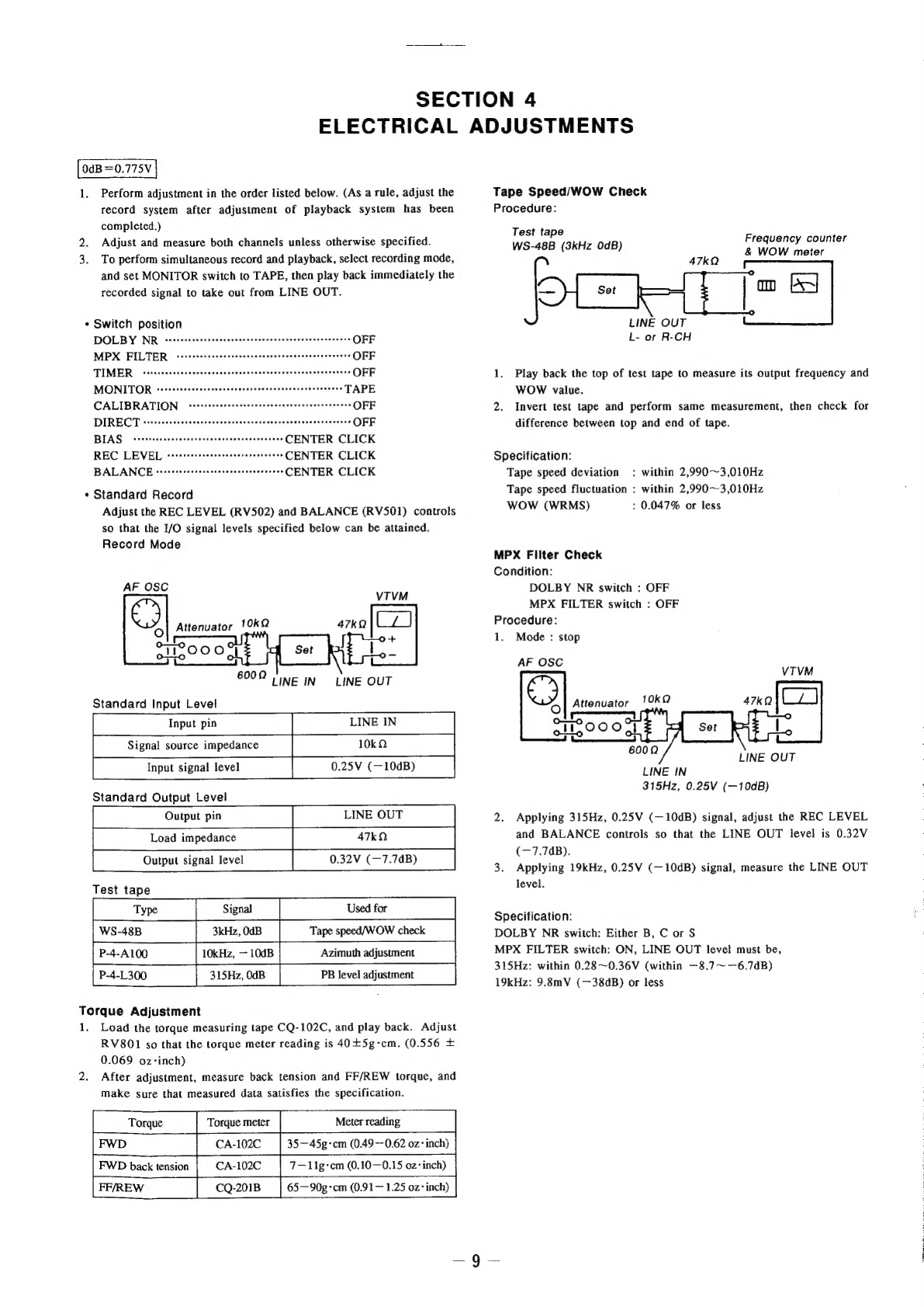
Standard
Record
Adjust
the
REC
LEVEL
(RV502)
and
BALANCE
(RV501)
controls
so
that
the
1/O
signal
levels
specified
below
can
be
attained.
Record
Mode
AF
OSC
©
[e)
Attenuator
10kQ
6002
LINE
OUT
LINE
IN
Standard
Input
Level
Input
pin
LINE
IN
10kQ
0.25V
(—10dB)
LINE
OUT
47kO
0.32V
(—7.7dB)
Signal
source
impedance
Input
signal
level
Standard
Output
Level
Output
pin
Load
impedance
Output
signal
level
Test
tape
Tape
speed/WOW
check
10kHz,
—
10dB
Azimuth
adjustment
P-4-L300
PB
level
adjustment
Torque
Adjustment
1.
Load
the
torque
measuring
tape
CQ-102C,
and
play
back.
Adjust
RV8O1
so
that
the
torque
meter
reading
is
40+5g-cm.
(0.556
+
0.069
oz-inch)
2.
After
adjustment,
measure
back
tension
and
FF/REW
torque,
and
make
sure
that
measured
data
satisfies
the
specification.
Torque
Torque
meter
Meter
reading
CA-102C
|
35—45g-cm
(0.49~-0.62
oz:
inch)
FWD
back
tension
CA-102C
7—11g-cem
(0.10—0.15
oz:
inch)
CQ-201B
|
65—90g-cm
(0.91—
1.25
oz
inch)
Tape
Speed/WOW
Check
Procedure:
Test
tape
WS-48B
(3kHz
OdB)
Frequency
counter
&
WOW
meter
LINE
OUT
L-
or
R-CH
1.
Play
back
the
top
of
test
tape
to
measure
its
output
frequency
and
WOW
value.
2.
Invert
test
tape
and
perform
same
measurement,
then
check
for
difference
between
top
and
end
of
tape.
Specification:
Tape
speed
deviation
:
within
2,990~3,010Hz
Tape
speed
fluctuation
:
within
2,990~3,010Hz
WOW
(WRMS)
:
0.047%
or
less
MPX
Filter
Check
Condition:
DOLBY
NR
switch
:
OFF
MPX
FILTER
switch
:
OFF
Procedure:
1.
Mode
:
stop
AF
OSC
9
Attenuator
eeeeneee
|
fo)
LINE
OUT
LINE
IN
315Hz,
0.25V
(—10dB)
2.
Applying
315Hz,
0.25V
(—10dB)
signal,
adjust
the
REC
LEVEL
and
BALANCE
controls
so
that
the
LINE
OUT
level
is
0.32V
(—7.7dB).
3.
Applying
19kHz,
0.25V
(—10dB)
signal,
measure
the
LINE
OUT
level.
Specification:
DOLBY
NR
switch:
Either
B,
C
or
S
MPX
FILTER
switch:
ON,
LINE
OUT
level
must
be,
315Hz:
within
0.28~0.36V
(within
—8.7~—6.7dB)
19kHz:
9.8mV
(—38dB)
or
less