MODEL
IDENTIFICATION
—
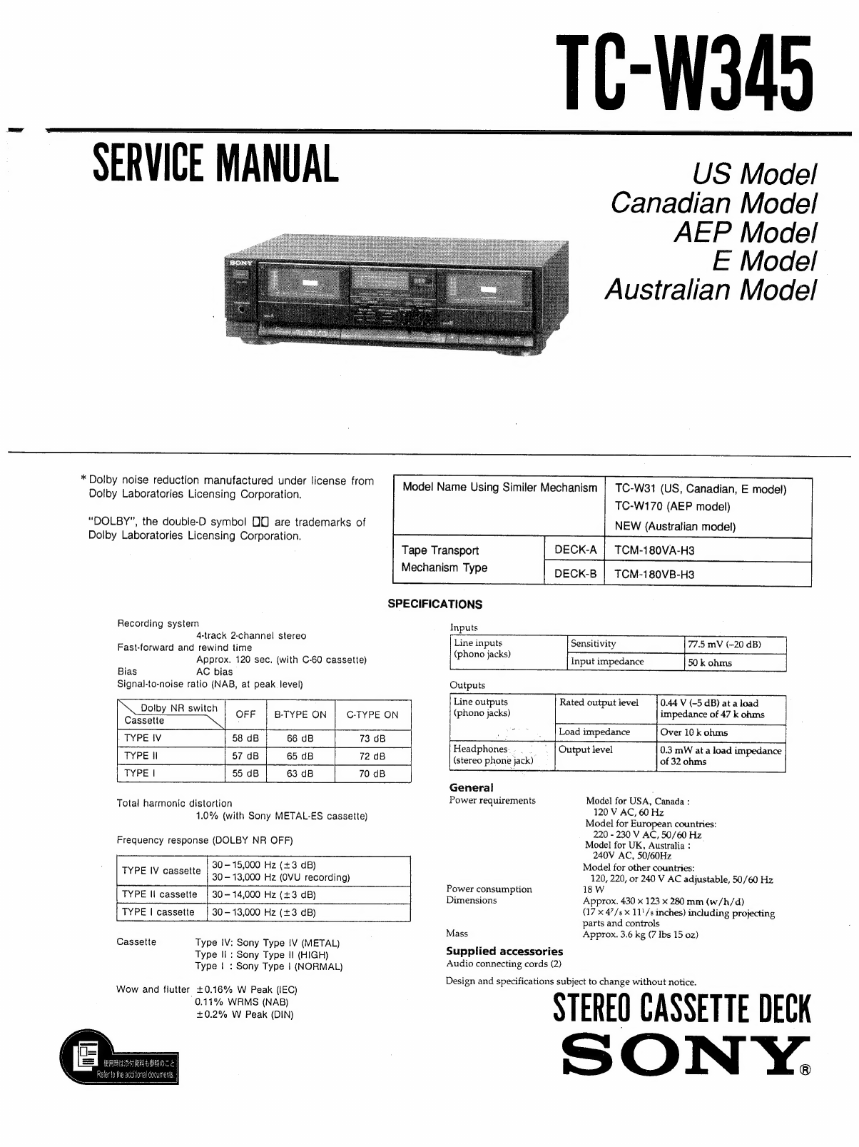
Specification
Label
—
SONY.
STEREO
CASSETTE
DECK
Whitt
MODEL
NO.
TC-W345
US,
Canadian
model:
AC
120V
60Hz
18W
AEP
model:
AC
220V~50/60Hz
18W
E
model:
AC
120,
220,
240V~50/60Hz
18W
Australian
model
:
AC
240V~50/60Hz
18W
TABLE
OF
CONTENTS
Section
Title
Page
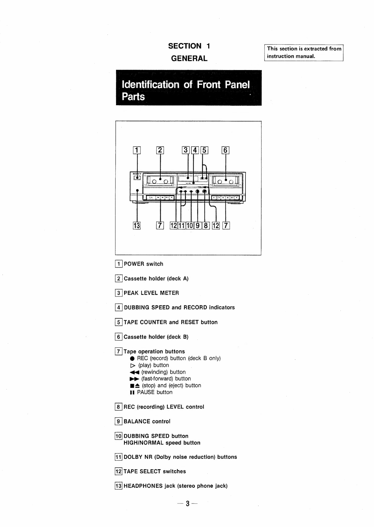
1.
GENERAL
GON
ING
HS:
PEM
55254
cs53h
ca
croneasscaszevunaeinconenedd
auahepeartunetettacteaias
3
2.
MECHANICAL
ADJUSTMENT..............:
cece
4
3.
ELECTRICAL
ADJUSTMENT
............:
cscs
4
Record/
Playback
Head
Azinuth
Adjustment
[Deck
A/
Deck
B]..
4
Tape
Speed
Adjustment
(Deck
A/
Deck
BJ...
ce
ceceeseereeees
4
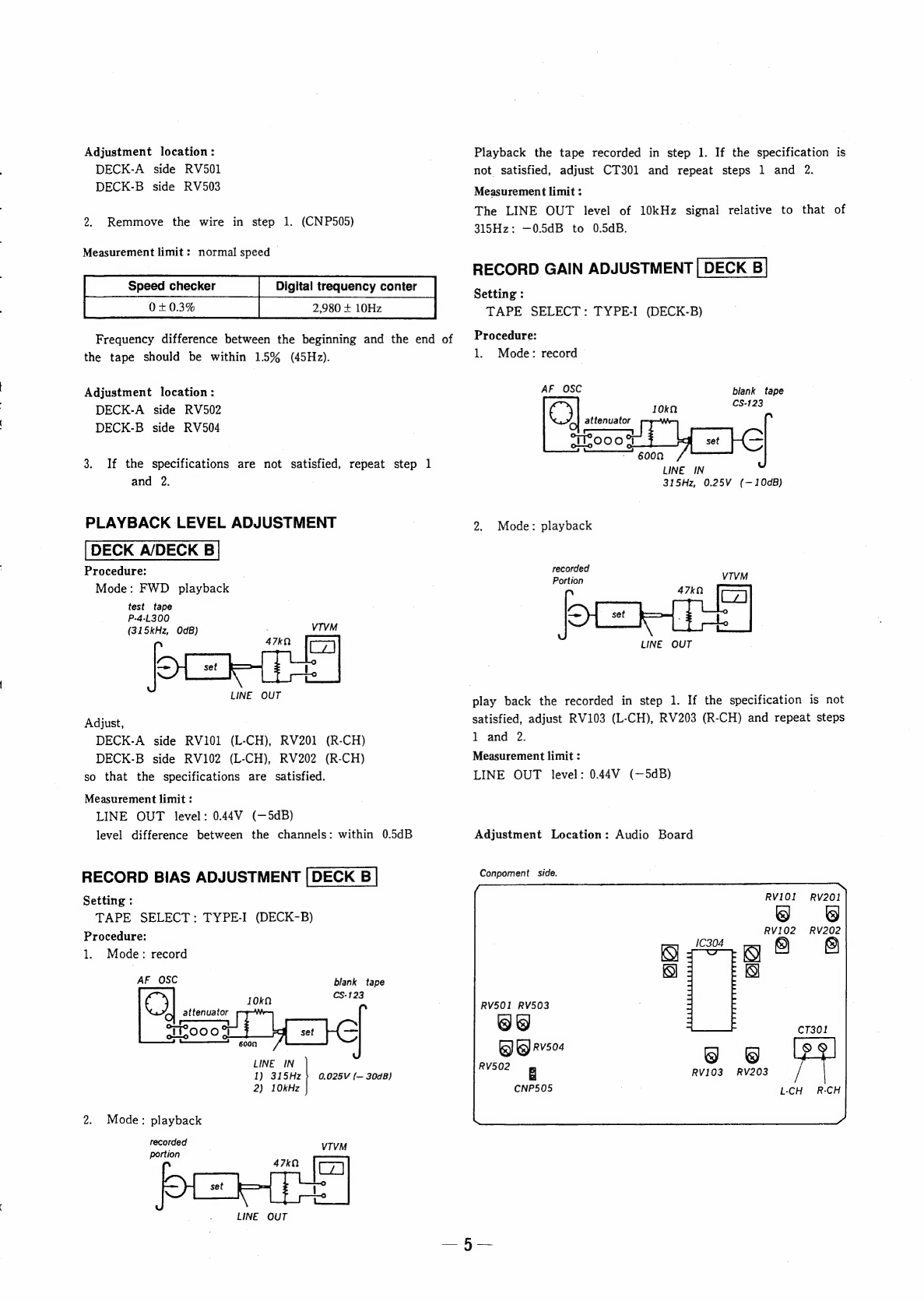
Playback
Level
Adjustment
[Deck
A/
Deck
Bl......c.ccccesseens
5
Record
Bias
Adjustment
[Deck
Bl}...
cecssesssesssessseeessessseseas
5
Record
Gain
Adjustment
|
Deck
BJ..........ccccsescceseeesseercsescseescsees
5
4.
DIAGRAMS
4-1.
Printed
Wiring
Boards
...........
ce
eceecessteeesstseeessseeesssserereees
6
4-2.
Schematic
Diagram
........eceseescseessseeseevesecsserssesseeseeeeaes
9
4-3.
IC
Block
Diagrams...
ccssecssecsesseneesssesssecsseeesessecsseesseanans
12
4-4.
Semiconductor
Lead
Layouts
..........cecscesecsseesseseeseeenes
13
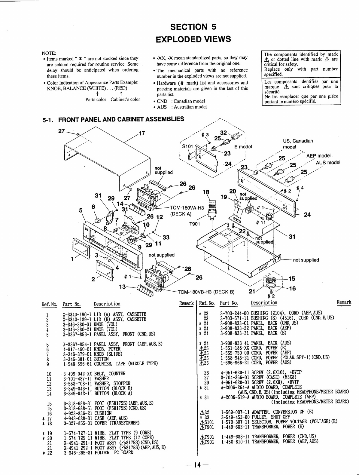
5.
EXPLODED
VIEWS
5-1.
Front
Panel
and
Cabinet
Assemblies
..............c:ccescssseeerees
14
5-2.
Mechanism
Deck
Section
(TCM-180VA-H3)
(DECK
A)
(TCM-180VB-H3)
(DECK
B)
uu...
cccecsessceeecsssesssesseeesessees
15
5-3.
Mechanism
Deck
Section2
(TCM-180VA-H3)
(DECK
A)
(TCM-180VB-H3)
(DECK
B)
.......cssscccsssersesssseuesesteverssentes
16
5-4.
Mechanism
Deck
Section3
(TCM-180VA-H3)
(DECK
A)
(TCM-180VB-H3)
(DECK
B)
.......ccesccrecesestesssesseravenverserens
17
6.
ELECTRICAL
PARTS
LIST
uo.
eeceeneeeees
18
SAFETY-RELATED
COMPONENT
WARNING!!
COMPONENTS
IDENTIFIED
BY
MARK
A
OR
DOTTED
LINE
WITH
MARK
A
ON
THE
SCHEMATIC
DIAGRAMS
AND
IN
THE
PARTS
LIST
ARE
CRITICAL
TO
SAFE
OPERATION.
REPLACE
THESE
COMPONENTS
WITH
'
SONY
PARTS
WHOSE
PART
NUMBERS
APPEAR
AS
SHOWN
IN
THIS
MANUAL
OR
IN
SUPPLEMENTS
PUB-
LISHED
BY
SONY.
SAFETY
CHECK-OUT
(US
model
only)
After
correcting
the
original
service
problem,
perform
the
following
safety
checks
before
releasing
the
set
to
the
customer:
Check
the
antenna
terminals,
metal
trim,
“metallized”
knobs,
screws,
and
all
other
exposed
metal
parts
for
AC
leakage.
Check
leakage
as
described
below.
LEAKAGE
The
AC
leakage
from
any
exposed
metal
part
to
earth
ground
and
from
all
exposed
metal
parts
to
any
exposed
metal
part
having
a
return
to
chassis,
must
not
exceed
0.5
mA
(500
microampers).
Leakage
current
can
be
measured
by
any
one
of
three
methods.
1.
Acommercial
leakage
tester,
such
as
the
Simpson
229
or
RCA
WT-540A.
Follow
the
manufacturers’
instructions
to
use
these
instruments.
2.
A
battery-operated
AC
milliammeter.
The
Data
Precision
245
digital
multimeter
is
suitable
for
this
job.
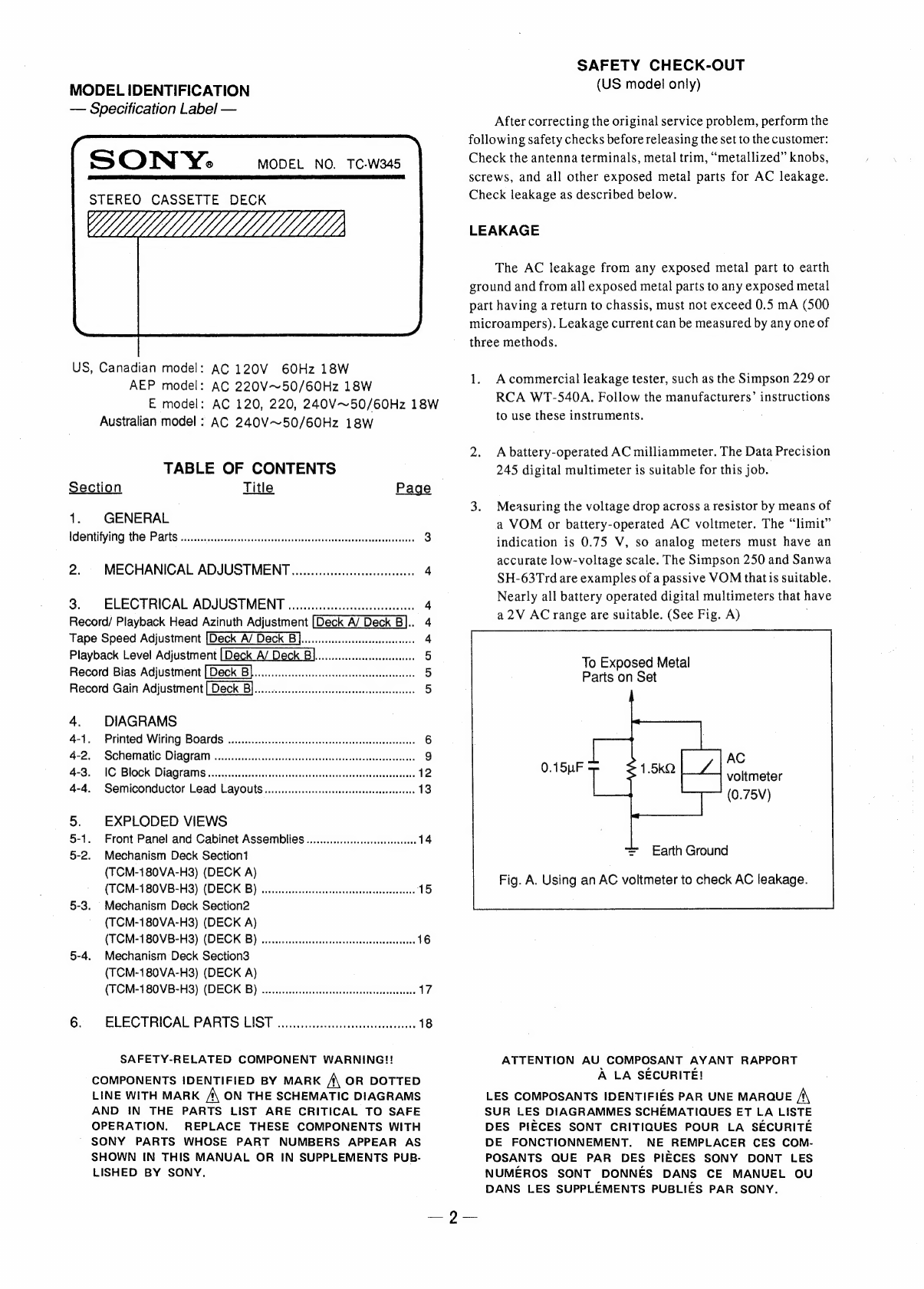
3.
Measuring
the
voltage
drop
across
a
resistor
by
means
of
a
VOM
or
battery-operated
AC
voltmeter.
The
“limit”
indication
is
0.75
V,
so
analog
meters
must
have
an
accurate
low-voltage
scale.
The
Simpson
250
and
Sanwa
SH-63Trd
are
examples
of
a
passive
VOM
thatis
suitable.
Nearly
all
battery
operated
digital
multimeters
that
have
a2V
AC
range
are
suitable.
(See
Fig.
A)
To
Exposed
Metal
Parts
on
Set
|
7
{Ac
Pee
voltmeter
(0.75V)
Earth
Ground
Fig.
A.
Using
an
AC
voltmeter
to
check
AC
leakage.
ATTENTION
AU
COMPOSANT
AYANT
RAPPORT
A
LA
SECURITE!
LES
COMPOSANTS
IDENTIFIES
PAR
UNE
MARQUE
SUR
LES
DIAGRAMMES
SCHEMATIQUES
ET
LA
LISTE
DES
PIECES
SONT
CRITIQUES
POUR
LA
SECURITE
DE
FONCTIONNEMENT.
NE
REMPLACER
CES
COM-
POSANTS
QUE
PAR
DES
PIECES
SONY
DONT
LES
NUMEROS
SONT
DONNES
DANS
CE
MANUEL
OU
DANS
LES
SUPPLEMENTS
PUBLIES
PAR
SONY.