Sony TC-SP55 User manual

1
TC-SP55
SERVICE MANUAL
TC-SP55 is the deck section in CMT-SP55TC,
and TC-SP55 is sold in the option as a tape
deck of CMT-SP55MD.
SPECIFICATIONS
STEREO CASSETTE DECK
Model Name Using Similar Mechanism NEW
Tape Transport Mechanism Type CMAL2Z720A
AEP Model
UK Model
E Model
Recording system 4-track 2-channel stereo
Frequency response (DOLBY NR OFF)
40 – 14,000 Hz (±3 dB)
using Sony TYPE I cassettes
40 – 15,000 Hz (±3 dB),
using Sony TYPE II cassettes
General
Dimensions (w/h/d) incl. projecting parts and controls
Approx. 202 x 101 x 283 mm
Mass Approx. 1.9 kg
Supplied accessory System cable (1)
Design and specifications are subject to change without notice.
w
w
w
.
x
i
a
o
y
u
1
6
3
.
c
o
m
Q
Q
3
7
6
3
1
5
1
5
0
9
9
2
8
9
4
2
9
8
T
E
L
1
3
9
4
2
2
9
6
5
1
3
9
9
2
8
9
4
2
9
8
0
5
1
5
1
3
6
7
3
Q
Q
TEL 13942296513 QQ 376315150 892498299
http://www.xiaoyu163.com

2
MODEL IDENTIFICATION
— BACK PANEL —
TABLE OF CONTENTS
1. SERVICING NOTE ·························································· 3
2. GENERAL ·········································································· 5
3. DISASSEMBLY
3-1. Case ···················································································· 6
3-2. Front Panel Assy ································································· 6
3-3. Mechanism Assy ································································· 7
3-4. Main Board ········································································· 7
3-5. Pinch Roller BLK Assy, Belt ·············································· 8
4. TEST MODE······································································ 9
5. MECHANICAL ADJUSTMENTS ····························· 11
6. ELECTRICAL ADJUSTMENTS ······························· 11
7. DIAGRAMS
7-1. Block Diagram ································································· 15
7-2. Schematic Diagram – Main Section – ······························ 16
7-3. Printed Wiring Board – Main Section – ··························· 17
7-4. Schematic Diagram – Panel Section – ····························· 18
7-5. Printed Wiring Board – Panel Section – ··························· 18
7-6. IC Pin Functions ······························································· 19
7-7. IC Block Diagrams ··························································· 20
8. EXPLODED VIEW
8-1. Case and Front Panel ························································ 21
9. ELECTRICAL PARTS LIST ······································· 22
• Abbreviation
AED : North European model
MY : Malaysia model
SP : Singapore model
MODEL
AEP, UK, AED models
MY, SP models
PARTS No.
4-229-654-0s
4-229-654-2s
Parts No.
SAFETY-RELATED COMPONENT WARNING!!
COMPONENTS IDENTIFIED BY MARK 0OR DOTTED
LINE WITH MARK 0ON THE SCHEMATIC DIAGRAMS
AND IN THE PARTS LIST ARE CRITICAL TO SAFE
OPERATION. REPLACE THESE COMPONENTS WITH
SONY PARTS WHOSE PART NUMBERS APPEAR AS
SHOWN IN THIS MANUAL OR IN SUPPLEMENTS
PUBLISHED BY SONY.
w
w
w
.
x
i
a
o
y
u
1
6
3
.
c
o
m
Q
Q
3
7
6
3
1
5
1
5
0
9
9
2
8
9
4
2
9
8
T
E
L
1
3
9
4
2
2
9
6
5
1
3
9
9
2
8
9
4
2
9
8
0
5
1
5
1
3
6
7
3
Q
Q
TEL 13942296513 QQ 376315150 892498299
http://www.xiaoyu163.com

3
SECTION 1
SERVICING NOTE
This unit cannot be repaired by itself.
When repairing, connect the whole system except for the speaker.
MCTest Mode
Procedure :
1. When the power ON, press the ?/1button (TA) while pressing TUNING MODE button (ST) and REPEAT button (CDP) together.
2. Frame of the MD mark and the CD mark flash, and “BASS/TRE FLAT” appears for a moment.
3. When the VOLUME knob (TA) is turned clockwise, “VOLUME MAX” appears for a moment.
4. When the VOLUME knob (TA) is turned counterclockwise, “VOLUME MIN” appears for a moment.
5. Select the function “TAPE” using the FUNCTION knob (TA).
Set the test tape AMS-110A or AMS-120.
6. Press DIRECTION button (TC) to enter either “j” (loop) or “h” (two way).
7. Press the CD SYNC REC button (TC) to start the AMS test.
8. Number of AMS signals is counted during the AMS test and the message “EDG#” (# means a number) appears. When the test tape
either AMS-110A or AMS-120 is used, the AMS signal is detected twice before shut off.
9. When the AMS test ends, either “OK” or “NG” appears.
10.To exit the MC test mode, either press the ?/1 button (TA) or perform the cold reset as described above.
(FWD) REW (Shut off)
(FWD) FF AMS
(FWD) REW AMS
END
(Shut off)
(Shut off)
Cold Reset
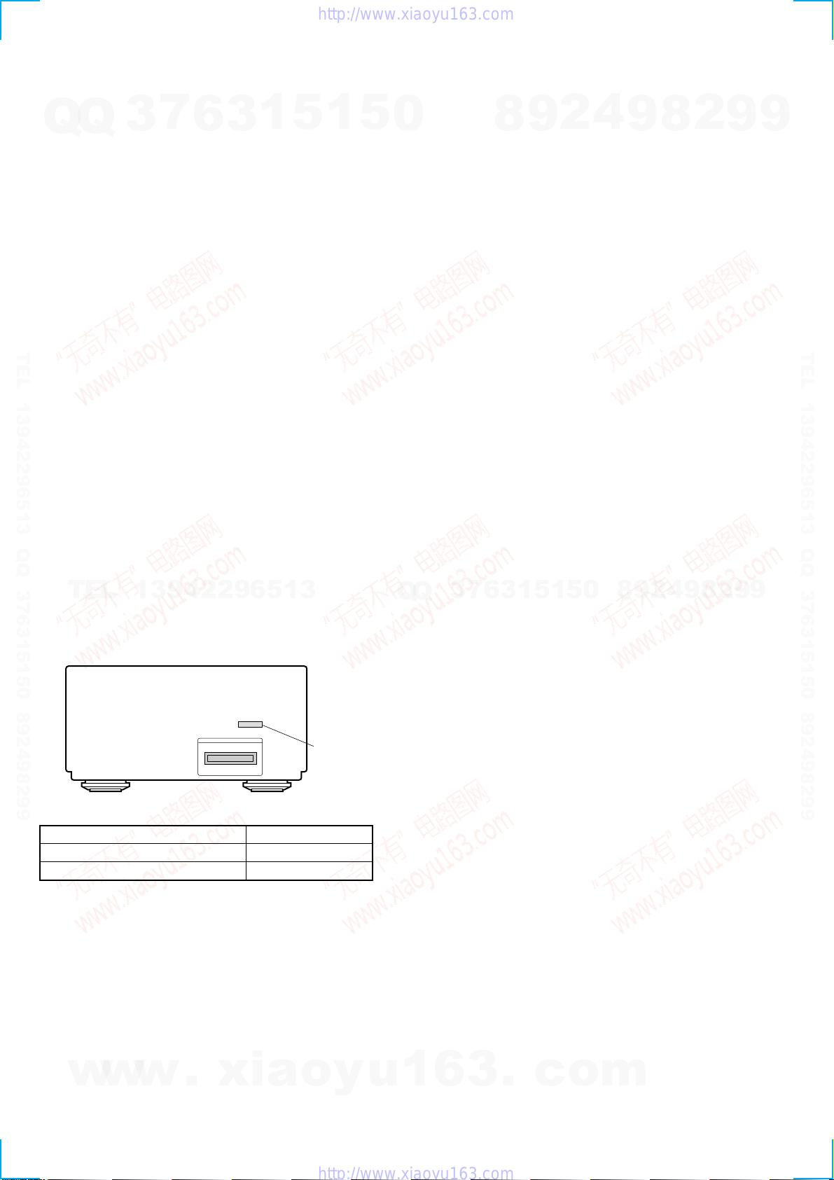
• When the AC cord is removed, COLD RESET is done with TC-SP55.
STTest Mode
Procedure :
1. When the power ON, press the ?/1button (TA) while pressing the TUNING MODE button (ST) and PLAY MODE buttons (CDP)
together.
2. LCD are all turned on.
3. Press TUNING MODE button (ST) to enter the model destination indecation mode. “SP55 CE2” or “SP55 ASIA2” appears.
4. Every pressing of TUNING MODE button (ST) changes the display in the following order.
MC Version tCD Version tST Version tTC Version tTA Version tTM Version tmodel destination display.
5. Press DISPLAY button (ST) and the date appears as “ 00615a ”
Every pressing of DISPLAY button (ST) changes the display in the Version display and model destination display.
6. Press TUNER/BAND button (ST) to enter the key check mode.
7. In the key check mode, the fluorescent indicator tube displays “Key 0 Vol 0”. Each time a button is pressed, “Key” value increases.
However, once a button is pressed, it is no longer taken into account.
“Vol” Value increases like “1, 2, 3 ...” if rotating VOLUME knob (TA) in the clockwise direction, or decreases like “0, 9, 8 ...” if rotating
in the counterclockwise diretion. (The TC-SP55 is not count.)
8. To exit from this mode, disconnect the power cord.
w
w
w
.
x
i
a
o
y
u
1
6
3
.
c
o
m
Q
Q
3
7
6
3
1
5
1
5
0
9
9
2
8
9
4
2
9
8
T
E
L
1
3
9
4
2
2
9
6
5
1
3
9
9
2
8
9
4
2
9
8
0
5
1
5
1
3
6
7
3
Q
Q
TEL 13942296513 QQ 376315150 892498299
http://www.xiaoyu163.com

4
Aging Mode
• Mode for repeating operations of the CD player and TC deck automatically.
When errors occur:
Aging stops and a message indicating that an error has occurred such as “CD MEC ERR” is displayed.
(For details of errors, refer to “Error History Display Mode”.)
When no errors occur:
Aging is repeatedly performed.
Procedure:
1. Load any CD and a tape.
2. Select the function “CD” using the FUNCTION knob (TA).
3. While pressing the TUNING MODE button (ST) and Hbutton (CDP), press the ?/1 button (TA).
4. “AGING” is displayed on the LCD briefly.
5. Operations are performed in the following sequence during aging.
Every pressing of DISPLAY button (ST) changes the display in the CD display and TAPE display.
Reading of TOC
Playback of first track (3sec.)
Playback of last track (3sec.)
CD tray open
CD tray close
CD : Cassette :
REW (Shut off) "TAPE AG-1"
PLAY
FF
REV PLAY
REW
(20 sec) "TAPE AG-2"
(20 sec) "TAPE AG-3"
(20 sec) "TAPE AG-4"
(20 sec) "TAPE AG-5"
FF search
REW search
OPEN
CLOSE
(20 sec) "TAPE AG-6"
(20 sec) "TAPE AG-7"
"TAPE AG-8"
"TAPE AG-9"
6. To end aging, execute the cold reset.
Error History Display Mode
Mode for checking the history of errors which have occurred in the CD player.
Execute this mode after ending the aging mode.
Procedure:
1. Select the function “CD” using the FUNCTION knob (TA).
2. While pressing the TUNING MODE button (ST) and Sbutton (CDP), press the ?/1button (TA).
3. “EMC@@EDC**” id displayed.
@@: Number of mechanism errors (Last 3 errors)
** : Number of errors (NO DISC ERROR) which occurred after chucking (Last 3 errors)
4. To end, press the ?/1button (TA) and turn OFF the power.
5. To erase the error history, perform cold reset.
(While pressing the TUNING MODE button (ST) and M L button (CDP), press the ?/1button.)
w
w
w
.
x
i
a
o
y
u
1
6
3
.
c
o
m
Q
Q
3
7
6
3
1
5
1
5
0
9
9
2
8
9
4
2
9
8
T
E
L
1
3
9
4
2
2
9
6
5
1
3
9
9
2
8
9
4
2
9
8
0
5
1
5
1
3
6
7
3
Q
Q
TEL 13942296513 QQ 376315150 892498299
http://www.xiaoyu163.com

5
SECTION 2
GENERAL
1CD SYNC REC button
2CD SYNC REC indicator
3zREC button
4zREC indicator
5hindicator
6Hindicator
7Sindicator
8Abutton
1 42 5 6 7 8
9
0
qaqsqdqfqgqh
3
9M L button
q; l m button
qa sbutton
qs Sbutton
qd Hbutton
qf hbutton
qg DIRECTION button
qh DOLBY NR button
w
w
w
.
x
i
a
o
y
u
1
6
3
.
c
o
m
Q
Q
3
7
6
3
1
5
1
5
0
9
9
2
8
9
4
2
9
8
T
E
L
1
3
9
4
2
2
9
6
5
1
3
9
9
2
8
9
4
2
9
8
0
5
1
5
1
3
6
7
3
Q
Q
TEL 13942296513 QQ 376315150 892498299
http://www.xiaoyu163.com

6
3-1. CASE
3-2. FRONT PANEL ASSY
Note: Follow the disassembly procedure in the numerical order given.
SECTION 3
DISASSEMBLY
Set Case Front Panel Assy Mechanism Assy (Page 7)
Main Board (Page 7) Pinch Roller BLK Assy, Belt (Page 8)
1two screws
(case 3 TP2
)
4case
1two screws
(case 3 TP2) 2
2
3
1connector
(CN702)
4screw (BVTP 3x8)
5front panel assy
2two screws
(BVTP 3x12)
3two foot assy's
claws
claws
w
w
w
.
x
i
a
o
y
u
1
6
3
.
c
o
m
Q
Q
3
7
6
3
1
5
1
5
0
9
9
2
8
9
4
2
9
8
T
E
L
1
3
9
4
2
2
9
6
5
1
3
9
9
2
8
9
4
2
9
8
0
5
1
5
1
3
6
7
3
Q
Q
TEL 13942296513 QQ 376315150 892498299
http://www.xiaoyu163.com

7
3-3. MECHANISM ASSY
3-4. MAIN BOARD
2two screws
(BVTP 3x10)
3mechanism assy
2two screws
(BVTP 3x10)
1connecto
r
(CN601)
1connector
(CN602)
1connector
(CN101)
2claw
2claw
1three screw
s
(BVTP 3x8)
4three screws
(BVTP 3x8)
3
5main board
w
w
w
.
x
i
a
o
y
u
1
6
3
.
c
o
m
Q
Q
3
7
6
3
1
5
1
5
0
9
9
2
8
9
4
2
9
8
T
E
L
1
3
9
4
2
2
9
6
5
1
3
9
9
2
8
9
4
2
9
8
0
5
1
5
1
3
6
7
3
Q
Q
TEL 13942296513 QQ 376315150 892498299
http://www.xiaoyu163.com

8
3-5. PINCH ROLLER BLK ASSY, BELT
1two screws
belt main
F/R belt
2mechanism deck
3claw
4pinch roller BLK R assy
6pinch roller BLK L assy
5claw
1two screws 7belt main
8F/R belt
w
w
w
.
x
i
a
o
y
u
1
6
3
.
c
o
m
Q
Q
3
7
6
3
1
5
1
5
0
9
9
2
8
9
4
2
9
8
T
E
L
1
3
9
4
2
2
9
6
5
1
3
9
9
2
8
9
4
2
9
8
0
5
1
5
1
3
6
7
3
Q
Q
TEL 13942296513 QQ 376315150 892498299
http://www.xiaoyu163.com

9
4-1-4.TC REC START POINT
Procedure:
1. Set the test mode, and press the REC button (TC) and then the Hbutton (TC) to set the recording state.
2. Pressing the CD SYNC REC button (TC) returns to the starting point of recording.
SECTION 4
TEST MODE
4-1. TEST MODE FOR NOT CONNECTING THE WHOLE SYSTEM
(When connectingTA-SP55,ST-SP55,TC-SP55)
4-1-1. SETTINGTHETEST MODE
Procedure:
1. When the power ON, press the ?/1 button (TA) while pressing the sbutton (TC) and CD SYNC REC buttons (TC) together.
2. When the test mode is set, the PAUSE LED will light up for 0.1 seconds at intervals of 3.2 seconds.
3. To exit the test mode, either press the ?/1 button (TA) and turn OFF the power.
4-1-2.TC AGING MODE
Procedure:
1. After setting the test mode, press the Hbutton (TC).
2. Operations are performed in the following sequence during aging.
REW (Shut off) "TAPE AG-1"
FWD
FF
REV
REW
(20 sec) "TAPE AG-2"
(20 sec) "TAPE AG-3"
(20 sec) "TAPE AG-4"
(20 sec)
(20 sec)
(20 sec)
"TAPE AG-5"
FF search
REW search
OPEN
CLOSE
"TAPE AG-6"
"TAPE AG-7"
"TAPE AG-8"
"TAPE AG-9"
4-1-3.TC AMS CHECK
Procedure:
1. After setting the test mode, pressing the sbutton (TC) and then the CD SYNC REC button (TC) will start REW operations.
2. After rewinding to the tape top,FF search in the FWD direction starts.
“TAPE EDG*” will be displayed.(*: Arbitrary number)
3. After FF searching to the tape end, the tape will be automatically stopped, and “TAPE OK” or “TAPE NG” will be displayed.
w
w
w
.
x
i
a
o
y
u
1
6
3
.
c
o
m
Q
Q
3
7
6
3
1
5
1
5
0
9
9
2
8
9
4
2
9
8
T
E
L
1
3
9
4
2
2
9
6
5
1
3
9
9
2
8
9
4
2
9
8
0
5
1
5
1
3
6
7
3
Q
Q
TEL 13942296513 QQ 376315150 892498299
http://www.xiaoyu163.com

10
4-2. TEST MODE FOR CONNECTINGTHE WHOLE SYSTEM
4-2-1.TC Aging Mode (ConnectingThe Whole System)
• Mode for repeating operations of the CD player and TC deck automatically.
When errors occur:
Aging stops and a message indicating that an error has occurred such as “CD MEC ERR” is displayed.
(For details of errors, refer to “Error History Display Mode”.)
When no errors occur:
Aging is repeatedly performed.
Procedure:
1. Load any CD and a tape.
2. Select the function “CD” using the FUNCTION knob(TA) .
3. While pressing the TUNING MODE button (ST) and Hbutton (CDP), press the ?/1 button (TA).
4. “AGING” is displayed on the fluorescent display tube briefly.
5. Operations are performed in the following sequence during aging.
Every pressing of DISPLAY button (ST) changes the display in the CD display and TAPE display.
Reading of TOC
Playback of first track (3sec.)
Playback of last track (3sec.)
CD tray open
CD tray close
CD : Cassette :
REW (Shut off) “TAPE AG-1”
PLAY
FF
REV PLAY
REW
(20 sec) “TAPE AG-2”
(20 sec) “TAPE AG-3”
(20 sec) “TAPE AG-4”
(20 sec) “TAPE AG-5”
FF search
REW search
OPEN
CLOSE
(20 sec) “TAPE AG-6”
(20 sec) “TAPE AG-7”
"TAPE AG-8"
"TAPE AG-9"
6. To end aging, execute the cold reset.
w
w
w
.
x
i
a
o
y
u
1
6
3
.
c
o
m
Q
Q
3
7
6
3
1
5
1
5
0
9
9
2
8
9
4
2
9
8
T
E
L
1
3
9
4
2
2
9
6
5
1
3
9
9
2
8
9
4
2
9
8
0
5
1
5
1
3
6
7
3
Q
Q
TEL 13942296513 QQ 376315150 892498299
http://www.xiaoyu163.com

11
3.04 – 6.96 N • m
(31 to 71 g • cm)
(0.43 – 0.98 oz • inch)
0.20 – 0.58 N • m
(2 to 6 g • cm)
(0.02 – 0.08 oz • inch)
3.04 – 6.96 N • m
(31 to 71 g • cm)
(0.43 – 0.98 oz • inch)
0.20 – 0.58 N • m
(2 to 6 g • cm)
(0.02 – 0.08 oz • inch)
6.97 – 14.02 N • m
(71 to 143 g • cm)
(0.98 – 1.99 oz • inch)
0.98 N • m or more
(100 g or more)
(3.53 oz or more)
0.98 N • m or more
(100 g or more)
(3.53 oz or more)
CQ-102C
CQ-102C
CQ-102RC
CQ-102RC
CQ-201B
CQ-403A
CQ-403R
Precaution
1. Clean the following parts with a denatured alcohol-moistened
swab:
record/playback heads pinch rollers
erase head rubber belts
capstan idlers
2. Demagnetize the record/playback head with a head demagne-
tizer.
3. Do not use a magnetized screwdriver for the adjustments.
4. After the adjustments, apply suitable locking compound to the
parts adjusted.
5. The adjustments should be performed with the rated power sup-
ply voltage unless otherwise noted.
Torque Measurement
SECTION 5
MECHANICAL ADJUSTMENTS
Mode
FWD
FWD
back tension
REV
REV
back tension
FF/REW
FWD tension
REV tension
Torque meter Meter reading
SECTION 6
ELECTRICAL ADJUSTMENTS
2. Turn the adjustment screw and check output peaks. If the peaks
do not match for L-CH and R-CH, turn the adjustment screw so
that outputs match within 1 dB of peak.
Record/Playback Head Azimuth Adjustment
Procedure:
1. Mode : FWD playback
Tape Signal Used for
P-4-A100
WS-48B
P-4-L300
10 kHz, –10 dB
3 kHz, 0 dB
315 Hz, 0 dB
Azimuth Adjustment
Tape Speed Adjustment
Level Adjustment
tast tape
P-4-A100
(10kHz, –10dB)
set
AUX OUT
(on ST-SP55)
47kΩ
level meter
L-CH
peak
R-CH
peak
screw
position
output
level within
1 dB
L-CH
peak R-CH
peak
screw
position
within 1dB
0 DB=0.775V
Note: Before starting the adjustment, measure performance of the
machine. Perform adjustment only when the measured
performances do not satisfy the specifications.
1. Demagnetize the record/playback head with a head demagnetizer.
2. Do not use a magnetized screwdriver for the adjustments.
3. After the adjustments, apply suitable locking compound to the
parts adjusted.
4. The adjustments should be performed with the rated power supply
voltage unless otherwise noted.
completed before performing recording circuit adjustment.)
5. The adjustments should be performed in the order given in this
service manual. (As a general rule, playback circuit adjustment
should be completed before performing recording circuit adjust-
ment.)
6. The adjustments should be performed for both L-CH and R-CH.
7. Switches and controls should be set as follows unless otherwise
specified.
w
w
w
.
x
i
a
o
y
u
1
6
3
.
c
o
m
Q
Q
3
7
6
3
1
5
1
5
0
9
9
2
8
9
4
2
9
8
T
E
L
1
3
9
4
2
2
9
6
5
1
3
9
9
2
8
9
4
2
9
8
0
5
1
5
1
3
6
7
3
Q
Q
TEL 13942296513 QQ 376315150 892498299
http://www.xiaoyu163.com

12
3. Phase check
Model: FWD playback
test tape
P-4-A100
(10kHz, –10dB)
R-CH
L-CH
set
47kW
47kW
oscilloscope
AUX OUT
(
on ST-SP55
)
VH
4. Perform steps 1 to 3 in the FWD playback mode.
5. Confirm that phase error between L-ch and R-ch is in the range
of same phase to 90 degrees.
6. After the adjustments, apply suitable locking compound to the
parts adjusted.
Adjustment Location:
Waveform of oscilloscope
in phase 45°90°135°180°
good wrong
Tape Speed Adjustment
Procedure:
1. Insert the WS-48B into deck.
2. Press the Hbutton of deck.
3. Adjust RV362 of the MAIN board so that the reading of the
frequency counter becomes 3000 ± 90 Hz.
Adjustment Location: MAIN board
SampleValue of Wow and flutter
W.RMS (JIS) less than 0.3%
(test tape: WS-48B)
test tape
WS-48B
(3kHz, 0dB)
set
AUX OUT
(on ST-SP55)
level mete
r
Adjust RV211 (L-CH) and RV261 (R-CH), so that adjustment within
the following adjustment level.
Adjustment level:
AUX OUT level: –8.2 ±0.5 dB (285 to 319 mV)
Level difference between the channels: within ±1.0 dB
Confirm that the AUX OUT level does not change even though
play and stop are repeated.
Playback Level Adjustment
Procedure:
Mode: FWD playback
test tape
P-4-L300
(315Hz, 0dB)
set
AUX OUT
(on ST-SP55)
level mete
r
Record Bias Adjustment
Procedure:
1. Record mode.
AF OSC
AUX IN (on ST-SP55)
1) 315 Hz
2) 10 kHz
blank tap
e
CS-123
set
attenuator 600 Ω
} 50 mV (–23.8 dB)
2. Playback mode.
3. Confirm playback the signal recorded in step 1 become adjust-
ment level as follows.
Note: You had better to refer “4-1-4. TC REC START POINT”
See page 9) when this adjustment
4. If these levels do not adjustment level, adjust the RV311 (L-CH)
and RV361 (R-CH), to repeat steps 1 to 3.
Adjustment level:
The playback outpout of 10 kHz level difference adjust
315 Hz reference should be 0 dB ± 0.5 dB.
recorded
position
set
AUX OUT
(on ST-SP55)
level mete
r
Adjustment scerw
(FWD mode)
Adjustment scerw
(REV mode)
w
w
w
.
x
i
a
o
y
u
1
6
3
.
c
o
m
Q
Q
3
7
6
3
1
5
1
5
0
9
9
2
8
9
4
2
9
8
T
E
L
1
3
9
4
2
2
9
6
5
1
3
9
9
2
8
9
4
2
9
8
0
5
1
5
1
3
6
7
3
Q
Q
TEL 13942296513 QQ 376315150 892498299
http://www.xiaoyu163.com

13
Record Level Adjustment
Procedure:
1. Record mode.
2. Playback mode.
3. Confirm playback the signal recorded in step 1 become adjust-
ment level as follows.
4. If these levels do not adjustment level, adjust the RV401 (L-CH)
and RV451 (R-CH), on the MAIN board to repeat steps 1 to 3.
Adjustment level:
LINE OUT level: –21.8 dB ± 0.5 dB (59.5 to 66.7 mV)
Adjustment Location: MAIN board
AF OSC
AUX IN (on ST-SP55)
315Hz 50 mV (–23.8 dB)
blank tap
e
CS-123
set
attenuator 600 Ω
recorded
position
set
AUX OUT
(on ST-SP55)
level mete
r
RV311 (L-CH),
RV361 (R-CH)
RECORD BIAS
RV211 (L-CH),
RV261 (R-CH)
PB LEVEL
RV401 (L-CH),
RV451 (R-CH)
REC LEVEL
TAPE SPEED
RV362
RV311
RV361
RV211
RV261
RV451 RV401
w
w
w
.
x
i
a
o
y
u
1
6
3
.
c
o
m
Q
Q
3
7
6
3
1
5
1
5
0
9
9
2
8
9
4
2
9
8
T
E
L
1
3
9
4
2
2
9
6
5
1
3
9
9
2
8
9
4
2
9
8
0
5
1
5
1
3
6
7
3
Q
Q
TEL 13942296513 QQ 376315150 892498299
http://www.xiaoyu163.com

14
SECTION 7
DIAGRAMS
THIS NOTE IS COMMON FOR PRINTED WIRING
BOARDS AND SCHEMATIC DIAGRAMS.
(In addition to this,the necessary note is printed
in each block.)
For schematic diagrams.
Note:
• All capacitors are in µF unless otherwise noted. pF: µµF
50 WV or less are not indicated except for electrolytics
and tantalums.
• All resistors are in Ωand 1/4W or less unless otherwise
specified.
•f: internal component.
•2: nonflammable resistor.
•5: fusible resistor.
•C: panel designation.
For printed wiring boards.
Note:
•X: parts extracted from the component side.
•Y: parts extracted from the conductor side.
•b: Pattern from the side which enables seeing.
(The other layers' patterns are not indicated.)
•U: B+ Line.
•V: B– Line.
•H: adjustment for repair.
• Voltages and waveforms are dc with respect to ground
under no-signal (detuned) conditions.
• Voltages are takenwitha VOM (Inputimpedance10 MΩ).
Voltage variations may be noted due to normal produc-
tion tolerances.
• Waveforms are taken with a oscilloscope.
Voltage variations may be noted due to normal produc-
tion tolerances.
• Circled numbers refer to waveforms.
• Signal path.
E: PB
a: REC
• Abbreviation
AED : North European model
MY : Malaysia model
SP : Singapore model
Note: The components identified by mark 0or dotted line
with mark 0are critical for safety.
Replace only with part number specified.
• Indication of transistor
C
BThese are omitted.
E
Q
B
These are omitted.
CE
B
These are omitted.
CE
•WAVEFORMS
– MAIN BOARD –
250Vp-p
2
T501 4
REC MODE 3T501 5
REC MODE
65Vp-p
125nsec
1
IC701 w; XOUT
4.5Vp-p
11.7µsec
11.7µsec
w
w
w
.
x
i
a
o
y
u
1
6
3
.
c
o
m
Q
Q
3
7
6
3
1
5
1
5
0
9
9
2
8
9
4
2
9
8
T
E
L
1
3
9
4
2
2
9
6
5
1
3
9
9
2
8
9
4
2
9
8
0
5
1
5
1
3
6
7
3
Q
Q
TEL 13942296513 QQ 376315150 892498299
http://www.xiaoyu163.com

15 15
TC-SP55
7-1. BLOCK DIAGRAM
: PB
: REC
•Signal Path
•R-ch is omitted due to same as L-ch.
DOLBY
TYPE B
Q502,503
BIAS
OSC
IC201
ERASE BIAS
L
R
RV211
REC/PB HEAD
TAPE MECHANISM ASSY
CMAL2Z720A
R CH
31
IC101
REC/PB
EQ OUT
T501
REC BIAS
46
48
16 21 50
PB-A/B
EQ IN 38
36
RV401
REC LEVEL
39 REC OUT
BIAS SW
70
120
+7V
-7V
Q501
LIN 43
PB
18
20
22
40
25
PB OUT
LM ON/
OFF
BIAS ON/OFF
RM ON/OFF
ALC ON/OFF
B NORM/CROM/
METAL
NORM/
HIGH
PAS
DOL
PR
X
DOLBY NR
RV311
REC
BIAS
PLAYBACK
LEVEL
33
23
24
NR ON/
OFF
VCC VEE
28 27 26
MS
19
27
17
29
37
36
35
34
41 42 24 25 26 23 22
8
32
7
30
16
31
33
14
13
6
HRPE101
ERASE HEAD
22
3
1
6
8
5
7
13
18
14
12
11
19
17
3 1
+5V
REG.
+12
REG.
3 1
SYSTEM
CONTROL
3
(FROM ST-SP55)
+UNREG(H)
+UNREG(L)
-UNREG(-)
DGND
MGND
I2C CLK
PDOWN
IC603
IC602
IC604
IC605
I2C-DATA
AGND
TC-R
REC-L
REC-R
TC-L
AGNDAGND
DGND
MGND
-7V
REG 16
-7V
+5V
15
3 1
RESET. D+5.6V
+12V
+7V
REG.
3 1
3 2
+7V
1
18
D603
IC702
l m
M L s
H
Ah
zREC
SHh
zREC
S
Q701-705
LED DRIVE
D911 D912
CD SYNC REC
D913 D914 D915
DOLBY NR
DIRECTION
CD SYNC
REC
S911 S910 S909 S908 S907 S906 S905 S904 S903 S902
S901
4
39
38
28
33
40
CAPSTAN
MOTOR M
LOADING
MOTOR M
10 6
2 5
IC601
MOTOR DRIVE
RV362
TAPE
SPEED Q603,604
SOL
DRIVE
SOLENOID
+12V
Q601,602
MOTOR
DRIVE
+12V
CRO2
PACK
FREC
+MTR
PREC
PLAY
R-CH
R-CH
D623
D624
D622
D621
AMS IN
TC-MUTE
DOLBY
PASS/PB/REC
BIAS
REC MUTE
ALC
DOLBY
BIAS
REC.M
ALC
REC.PB.P
TC.M
AMS
I2C-DATA
I2C-CLK
DOWN
VCC
RESET
KEY1
KEY0
PAUSE LED
FWD LED
REV LED
REC LED
SYNC REC
LED
TC-RELAY
+MTR
+SOL
PACK
SENSOR OUT
B-HALF
PLAY SW
LOAD OUT
LOAD IN
LOAD OUT SW
LOAD IN SW
OUT SW
IN SW
OUT 2
OUT 1
IN 2
IN1
IC401
DDOLBY NR
AMS
DOLBY
TC.M
REC.PB.P
BIAS
REC.M
ALC
+7V -7V
09
IC701
SYSTEM
CONTROL
CN701
w
w
w
.
x
i
a
o
y
u
1
6
3
.
c
o
m
Q
Q
3
7
6
3
1
5
1
5
0
9
9
2
8
9
4
2
9
8
T
E
L
1
3
9
4
2
2
9
6
5
1
3
9
9
2
8
9
4
2
9
8
0
5
1
5
1
3
6
7
3
Q
Q
TEL 13942296513 QQ 376315150 892498299
http://www.xiaoyu163.com

16 16
TC-SP55
7-2. SCHEMATIC DIAGRAM – MAIN SECTION – • See page 14 forWaveforms. • See page 19 for IC Pin Functions. • See page 20 for IC Block Diagrams.
PIN
FUNCTION
w
w
w
.
x
i
a
o
y
u
1
6
3
.
c
o
m
Q
Q
3
7
6
3
1
5
1
5
0
9
9
2
8
9
4
2
9
8
T
E
L
1
3
9
4
2
2
9
6
5
1
3
9
9
2
8
9
4
2
9
8
0
5
1
5
1
3
6
7
3
Q
Q
TEL 13942296513 QQ 376315150 892498299
http://www.xiaoyu163.com

17 17
TC-SP55
7-3. PRINTEDWIRING BOARD – MAIN SECTION –
There are a few cases that the part isn’t mounted in
model is printed on diagram.
D601 A-1
D602 A-1
D603 A-4
D604 A-4
D611 C-1
D621 A-5
D622 A-5
D623 A-5
D624 A-5
D701 A-2
IC101 B-6
IC201 C-7
IC401 C-4
IC601 D-2
IC602 A-4
IC603 B-4
IC604 D-6
IC605 B-5
IC701 B-3
IC702 A-2
Q501 D-6
Q502 D-7
Q503 D-7
Q601 C-2
Q602 B-1
Q603 C-2
Q604 B-1
Q701 C-2
Q702 C-2
Q703 C-2
Q704 C-2
Q705 B-2
• Semiconductor
Location
Ref.No. Location
w
w
w
.
x
i
a
o
y
u
1
6
3
.
c
o
m
Q
Q
3
7
6
3
1
5
1
5
0
9
9
2
8
9
4
2
9
8
T
E
L
1
3
9
4
2
2
9
6
5
1
3
9
9
2
8
9
4
2
9
8
0
5
1
5
1
3
6
7
3
Q
Q
TEL 13942296513 QQ 376315150 892498299
http://www.xiaoyu163.com

18 18
TC-SP55
7-4. SCHEMATIC DIAGRAM – PANEL SECTION –
7-5. PRINTEDWIRING BOARD – PANEL SECTION –
There are a few cases that the part isn’t mounted in
model is printed on diagram.
D911 C-2
D912 C-3
D913 C-4
D914 A-6
D915 A-7
• Semiconductor
Location
Ref.No. Location
w
w
w
.
x
i
a
o
y
u
1
6
3
.
c
o
m
Q
Q
3
7
6
3
1
5
1
5
0
9
9
2
8
9
4
2
9
8
T
E
L
1
3
9
4
2
2
9
6
5
1
3
9
9
2
8
9
4
2
9
8
0
5
1
5
1
3
6
7
3
Q
Q
TEL 13942296513 QQ 376315150 892498299
http://www.xiaoyu163.com

19
1 VCC — Power supply.(+5V)
2 VREF — Analog Reference Voltage.
3 AVSS — Ground.
4 NC — Not used.
5 NC — Not used.
6 P.DOWN I POWER DOWN signal control signal input. H: Normal L: STANDBY mode
7 DOLBY O DOLBY B NR control signal output. H: ON L: OFF
8 AMS IN I AMS search signal input.
9 NC — Not used.
10 NC — Not used.
11 NC — Not used.
12 NC — Not used.
13 I2C-CLK I/O IIC bus clock input/output.
14 I2C-DATA I/O IIC bus data input/output.
15 CNVSS — Connected to ground.
16 BIAS O REC bias control signal output. H: ON L: OFF
17 +MTR O Capstan Motor control. H: ON L: OFF
18 RESET I Reset signal input. L: RESET
19 XIN I Ceramic oscillator input.(8MHz)
20 XOUT O Ceramic oscillator output.(8MHz)
21 VSS — Ground.
22 SYNC REC LED O CD SYNC LED control signal output. H: OFF L: ON
23 REC LED O REC LED control signal output. H: OFF L: ON
24 PAUSE LED O PAUSE LED control signal output. H: OFF L: ON
25 FWD LED O FWD LED control signal output. H: OFF L: ON
26 REV LED O REV LED control signal output. H: OFF L: ON
27 TC-RELAY O Head REC/PB select signal output. H: REC L: PB
28 PLAY SW I MC PLAY switch signal input.
29 +SOL O MC mode exchange solenoid control signal output.
30 REC/PB/PASS I/O REC/PB/PASS select . H: REC PASS L: REC mode 1/2Vcc: PB MODE
31 REC MUTE O REC MUTE control. H: ON L: OFF
32 TC-MUTE O TC LINE MUTE control signal output. H: ON L: OFF
33 ALC O Automatic level control signal output. H: OFF L: ON
34 LOAD IN SW I Detection input from the tray open/close switch. H: LOAD IN
35 LOAD OUT SW I Detection input from the tray open/close switch. L: LOAD OUT
36 LOAD IN O Tray loading motor LOAD IN signal output. H: ON L: OFF
37 LOAD OUT O Tray loading motor LOAD OUT signal output. H: ON L:OFF
38 PACK I Detection input from the cassette half switch. H: HALF OFF L: HALF ON (H:without a half L: within a half)
39 B-HALF I REC proof detect signal input.
40 SENSOR OUT I Reel senser signal input.
41 KEY1 I Key input.
42 KEY0 I Key input.
Function
Pin NamePin No. I/O
• IC701 M38513M4-C59FP SYSTEM CONTROL (MAIN BOARD)
7-6. IC PIN FUNCTIONS
w
w
w
.
x
i
a
o
y
u
1
6
3
.
c
o
m
Q
Q
3
7
6
3
1
5
1
5
0
9
9
2
8
9
4
2
9
8
T
E
L
1
3
9
4
2
2
9
6
5
1
3
9
9
2
8
9
4
2
9
8
0
5
1
5
1
3
6
7
3
Q
Q
TEL 13942296513 QQ 376315150 892498299
http://www.xiaoyu163.com

20
IC101 µPC1330HA (MAIN BOARD)
IC601 LB1641 (MAIN BOARD)
7-7. IC BLOCK DIAGRAMS
12 3 45 6 7 8 9 10
GND
MOTOR
DRIVE
NOISE
FILTER
CLAMP
FWD.IN
REV.IN
VCC 1
VCC 2
NOISE
FILTER
MOTOR
DRIVE
MOTOR
DRIVE
MOTOR
DRIVE
T.S.D O.C.P
FWD/REV/STOP
CONTROL LOGIC
12345 6 7 8 9
INVERTER
COMPARATER
SW R1 GND SW P1 CONT GND VCC SW P2 GND SW R2
w
w
w
.
x
i
a
o
y
u
1
6
3
.
c
o
m
Q
Q
3
7
6
3
1
5
1
5
0
9
9
2
8
9
4
2
9
8
T
E
L
1
3
9
4
2
2
9
6
5
1
3
9
9
2
8
9
4
2
9
8
0
5
1
5
1
3
6
7
3
Q
Q
TEL 13942296513 QQ 376315150 892498299
http://www.xiaoyu163.com
Other manuals for TC-SP55
1
Table of contents
Other Sony Cassette Player manuals

Sony
Sony Walkman WM-FX551 User manual

Sony
Sony TC-K611S User manual

Sony
Sony WM-FX521 - Walkman User manual

Sony
Sony WM-FX321 User manual

Sony
Sony Walkman WM-FX491ST User manual

Sony
Sony TC-K333ESG User manual

Sony
Sony CFS-W338S User manual

Sony
Sony Walkman WM-FX277 User manual

Sony
Sony CFS-W338 User manual

Sony
Sony ICF-SW1000TS User manual

Sony
Sony CFS-W501L/S User manual

Sony
Sony Sports Walkman WM-FS111 User manual

Sony
Sony TC-TX5 User manual

Sony
Sony TC-D505 User manual

Sony
Sony Walkman WM-GX788 User manual

Sony
Sony Pressman TCS-60DV User manual

Sony
Sony M-530V User manual

Sony
Sony Walkman WM-EX20 User manual

Sony
Sony CFS-W338 User manual

Sony
Sony Walkman WM-EX610 User manual