TABLE
OF
CONTENTS
E
|
Section
Title
Page
Specifications
«errreeesesreeeeeeees
aeanoraeee
seanacuee:
seeeeseeeeeesenseeenes
1
1.
GENERAL.....-+-+++
apaaiess
uiaceasstiie
Usaalihaahaed
Seosionalohese
ee
.
2.
MECHANICAL
ADJUSTMENTS
-+---------+-
be
eAtetatees
seioaga
3
3.
ELECTRICAL
ADJUSTMENTS
-..-
myteeus
ecvcaninns
ere
saved
4.
DIAGRAMS
|
4-1,
Printed
Wiring
Boards-rrrcecsssccesstreeeeetees
sevsecnseen
4
4-2,
Schematic
Diagramerssrrccesseeeeseeeeeeeees
seaseeseeeseeseee
7
5,
EXPLODED
VIEWS
----.----
ie
iene
icaeuen
ee
10
6.
ELECTRICAL
PARTS
LIST
-ccccccsseecceccreeeeeees
sees
12
SERVICE
NOTE
Repairing
printed
resistor
Cut
both
sides
of
the
resistor
and
solder
the
carbon
resistor
having
same
value
in
place
of
printed
one
of
the
conductor
side.
1/32W
carbon
resistor
is
supplied
for
the
replacing
part
of
the
printed
resistor.
,
Notes
on
chip
component
replacement
Never
reuse
a
disconnected
chip
component.
Notice
that
the
minus
side
of
a
tantalum
capacitor
may
be
damaged
by
heat.
a
AE
aR
a
iL
ee
a
a
A
|
ee
th
at
ee
eae
cate
cet
eae
ee
ee
ee
ee
ee
ee
ee
ae
ae
i
ee
a
i
ee
ee
ee
SECTION
1
GENERAL
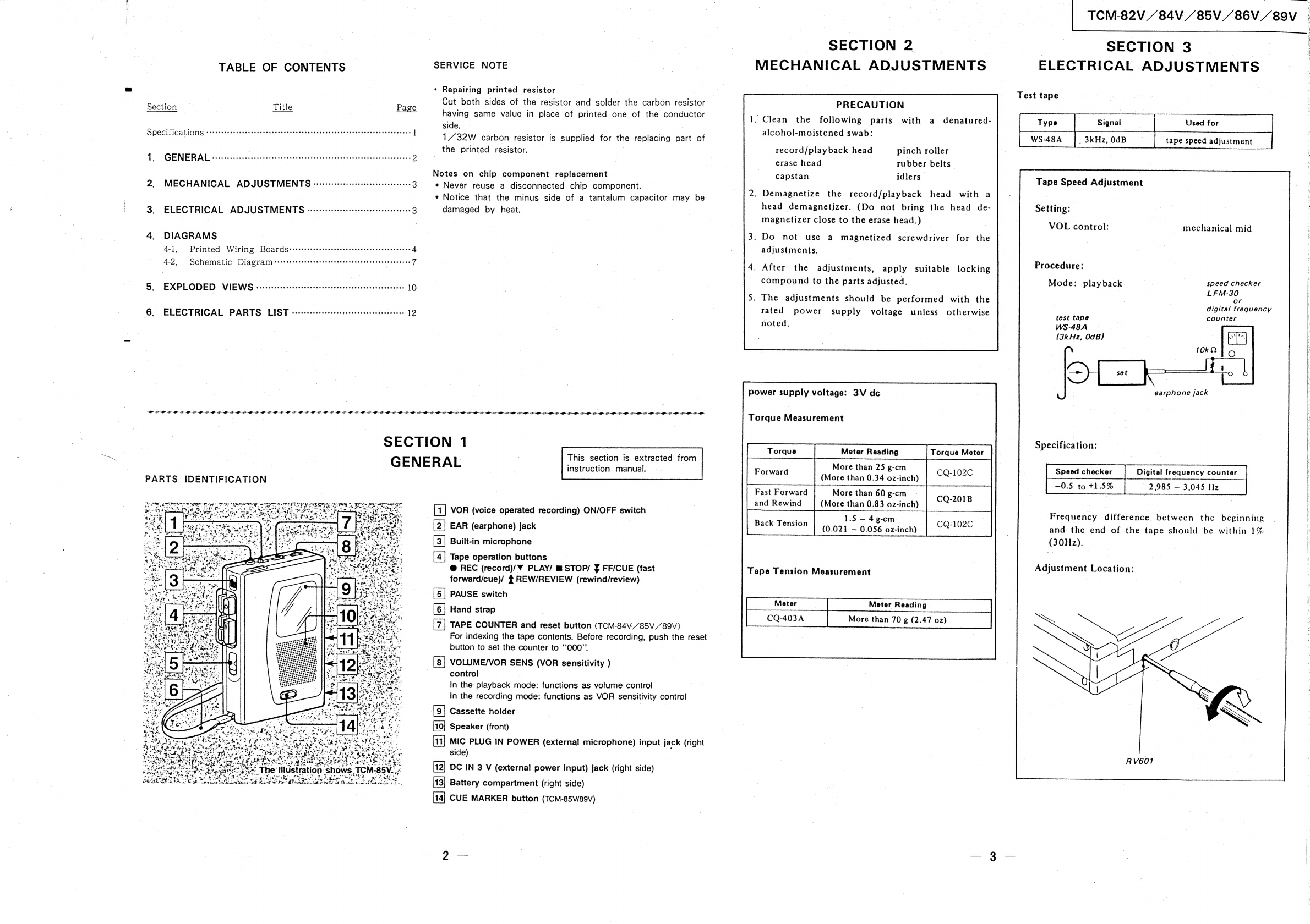
PARTS
IDENTIFICATION
-
«
a
J
Cae
LG
Mean
gi
uae.
VO
eae
gee
,
*
’
ae
wap
ag
sig
|
.
is
‘
ws
.
S
hata
og
te
de
oo,
Dy
tye
PSI
ws
ge
rat
aeeaeds
>
ee
tetas
tim
2
Bea
i
se
Pe
a
OR
Pa
Ne
ee
Tae
be
et
bale
Se
|
Lin
a
we
tos!
BP
ne
eecs
foot
mele
DSK
Lind
ok
ace
tote,
ics
eigenen’
“scqig
ti
ges
wan
eer
SAS
rd
Sy
BS
RE
*
-
.
vee
“
*
a
8
ee
SEE
©
ae
ete
ne
-
4
*
vet
wea
3
i
<,
Ls
on
Taian
ttat
ee
al
ages
tO.
rd
ae
hg
»
tS
‘o
A
piss
is
mg
FY
by
we
gies
POR
eo
mae
t
8,
S
ppekee”
A:
5
Tale
‘
ve
be
we,
.
aa
:
ord
aera
ae
oe
4
Foal
She
aN
‘N
ee
‘
.
ae
Ke
he
ES
ected
ES
a.
ate
see
OT
ee
+
a
aE
a
see
s
_
.
eer
¥,
.
*,
:
wre
5
aot
poe
oe.
ae
o
Ons
'ge
Z
|
:
org
A
*
oh.
®
é
an
2
mw
Poe:
es
4
ben
ad
>
Pd
é
star
af
Oa
Cae
te
truer
a
<
2
Re
TRAE
rhe
ae
srs
iT
pe
rae
Pane
ee
ete
Rees
“>.
The
illustration
s
et
E
ary
-
7
rane
.
’
~
oe
See
Sl!
ate.
ERNE
fee
TAS
hows
TCM-85V..
OCR
Crores
eee
Soe
‘
se:
&
t
ep”
a
e
ae
ee
=I
[3]
[2]
1
ifeyie]
TIS]
EES
This
section
is
extracted
from
instruction
manual.
VOR
(voice
operated
recording)
ON/OFF
switch
EAR
(earphone)
jack
|
Built-in
microphone
Tape
operation
buttons
@
REC
(record)/¥
PLAY/
@STOP/
¥
FF/CUE
(fast
forward/cue)/
4
REW/REVIEW
(rewind/review)
PAUSE
switch
Hand
strap
TAPE
COUNTER
and
reset
button
(TCM-84V_85V_
/89V)
For
indexing
the
tape
contents.
Before
recording,
push
the
reset
button
to
set
the
counter
to
‘‘O00"’.
VOLUME/VOR
SENS
(VOR
sensitivity
)
control
In
the
playback
mode:
functions
as
volume
control
In
the
recording
mode:
functions
as
VOR
sensitivity
control
Cassette
holder
Speaker
(front)
MIC
PLUG
IN
POWER
(external
microphone)
input
jack
(right
side)
DC
IN
3
V
(external
power
input)
jack
(right
side)
Battery
compartment
(right
side)
4]
CUE
MARKER
button
(TCM-85va9v)
SECTION
2
MECHANICAL
ADJUSTMENTS
PRECAUTION
.
Clean
the
following
parts
with
a
denatured-
alcohol-moistened
swab:
record/play
back
head
erase
head
pinch
roller
rubber
belts
capstan
idlers
Demagnetize
the
record/playback
head
with
a
head
demagnetizer.
(Do
not
bring
the
head
de-
magnetizer
close
to
the
erase
head.)
Do
not
use
a
magnetized
screwdriver
for
the
adjustments.
After
the
adjustments,
apply
suitable
locking
compound
to
the
parts
adjusted.
.
The
adjustments
should
be
performed
with
the
rated
power
supply
voltage
unless
otherwise
noted,
power
supply
voltage:
3V
dc
Torque
Measurement
Meter
Reading
Torque
Meter
More
than
25
g-cm
(More
than
0.34
oz-inch)
More
than
60
g-cm
and
Rewind
(More
than
0.83
02-inch)
1.5
—
4
g-cm
PACK
Pension’.
9:63
=
0056
o2inch)
Tape
Tenslon
Measurement
More
than
70
g
(2.47
oz)
Forward
CQ-102C
Fast
Forward
CQ-201B
CQ-102C
CQ403A
TCM-82V
/84V
/85V
/86V//89V
|
SECTION
3
eo
|
ELECTRICAL
ADJUSTMENTS
Test
tape
WS-48A
Signal
sd
Used
for
_3kHz,0dB
tape
speed
adjustment
Tape
Speed
Adjustment
Setting:
VOL
control:
mechanical
mid
Procedure:
Mode:
playback
speed
checker
LFM-30
or
digital
frequency
test
tape
counter
WS-48A
(3k
Hz,
OdB)
earphone
jack
Specification:
Speed
checker
—0.5
to
+1.5%
Digital
frequency
counter
2.985
—
3.045
Hz
Frequency
difference
between
the
beginning
and
the
end
of
the
tape
should
be
within
1%
(30Hz).
Adjustment
Location:
RV601


