DESCRIPTIONREF.NO. KANRI
NO.
PARTNO. KANRI
NO.
REF.NO. DESCRIPTIONPARTNO. DESCRIPTIONREF.NO. KANRI
NO.
PARTNO. KANRI
NO.
REF.NO. DESCRIPTIONPARTNO.
ELECTRICAL MAIN PARTS LIST
IC
87-A20-460-040 IC,MM1336CF
87-017-805-080 IC,AN7375NS(OP AMP)
TRANSISTOR
87-026-264-080 C-TR,RN1411
89-327-125-080 CHIP TR,2SC2712GR
DIODE
87-A40-630-040 C-DIODE, RB411D
87-020-027-080 CHIP-DIODE 1SS184
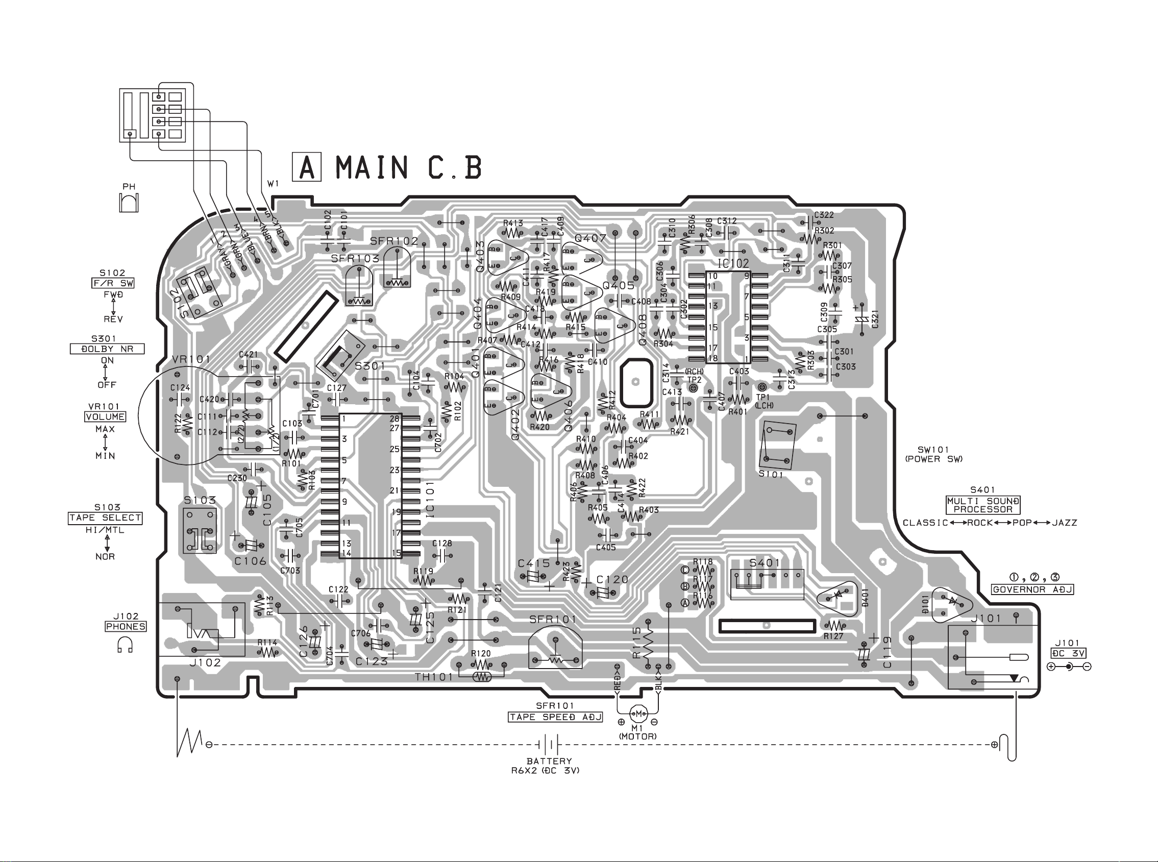
MAIN C.B
C101 87-010-178-080 CHIP CAP 1000P
C102 87-010-178-080 CHIP CAP 1000P
C103 87-010-213-080 C-CAP,S 0.015-50 B
C104 87-010-213-080 C-CAP,S 0.015-50 B
C105 87-010-499-040 E/CAP GAS 22-6.3 M 5L SRE
C106 87-010-499-040 E/CAP GAS 22-6.3 M 5L SRE
C111 87-010-182-080 C-CAP,S 2200P-50 B
C112 87-010-182-080 C-CAP,S 2200P-50 B
C119 87-010-503-040 CAP,E 220-4 M 5L SRE
C120 87-016-350-040 CAP,E 470-4 MA GAS
C121 87-016-462-080 C-CAP,S 1-16 ZF
C122 87-010-178-080 C-CAP,S 1000P-50 KB
C123 87-010-495-040 CAP,E 2.2-50 M 5L SRE
C124 87-010-596-080 CAP, S 0.047-16
C125 87-010-499-040 CAP,E 22-6.3 GAS
C126 87-010-503-040 CAP,E 220-4 GAS
C127 87-010-197-080 CAP, CHIP 0.01 DM
C128 87-010-196-080 CHIP CAPACITOR,0.1-25
C230 87-010-178-080 C-CAP,S 1000P-50 KB
C301 87-010-196-080 CHIP CAPACITOR,0.1-25
C302 87-010-196-080 CHIP CAPACITOR,0.1-25
C303 87-016-461-080 C-CAP,S 0.47-16F
C304 87-016-461-080 C-CAP,S 0.47-16F
C305 87-010-186-080 CAP,CHIP 4700P
C306 87-010-186-080 CAP,CHIP 4700P
C307 87-010-186-080 CAP,CHIP 4700P
C308 87-010-186-080 CAP,CHIP 4700P
C309 87-010-193-080 CHIP CAPACITOR,0.033
C310 87-010-193-080 CHIP CAPACITOR,0.033
C311 87-016-462-080 C-CAP,S 1-16 ZF
C312 87-016-462-080 C-CAP,S 1-16 ZF
C313 87-016-462-080 C-CAP,S 1-16 ZF
C314 87-016-462-080 C-CAP,S 1-16 ZF
C321 87-A10-952-080 C-CAP,TN 22-4 M A MCM
C322 87-010-196-080 CHIP CAPACITOR,0.1-25
C403 87-010-197-080 CAP, CHIP 0.01 DM
C404 87-010-197-080 CAP, CHIP 0.01 DM
C405 87-012-141-080 CHIP-CAPACITOR,0.22-16F
C406 87-012-141-080 CHIP-CAPACITOR,0.22-16F
C407 87-016-462-080 C-CAP,S 1-16 ZF
C408 87-016-462-080 C-CAP,S 1-16 ZF
C409 87-010-195-080 C-CAP,S 0.068-25 F
C410 87-010-195-080 C-CAP,S 0.068-25 F
C411 87-010-188-080 CAP,CHIP 6800P
C412 87-010-188-080 CAP,CHIP 6800P
C413 87-010-198-080 CAP, CHIP 0.022
C414 87-010-198-080 CAP, CHIP 0.022
C415 87-010-501-040 E/CAP GAS 47-4
C417 87-010-198-080 CAP, CHIP 0.022
C418 87-010-198-080 CAP, CHIP 0.022
C420 87-016-462-080 C-CAP,S 1-16 ZF
C421 87-016-462-080 C-CAP,S 1-16 ZF
C701 87-012-157-080 C-CAP,S 330P-50 CH
C702 87-012-157-080 C-CAP,S 330P-50 CH
C703 87-010-196-080 CHIP CAPACITOR,0.1-25
C704 87-010-197-080 C-CAP,S 0.01-25 KB
C705 87-010-197-080 C-CAP,S 0.01-25 KB
C706 87-016-461-080 C-CAP,S 0.47-16 ZF
J101 87-A60-849-010 JACK,DC DIA 2.75 BLK
J102 85-HRL-623-010 JACK,3.5 BLK ST BLK
R115 87-022-657-080 RES,0.68-1/8W G 4300
S101 87-A91-077-010 SW,LEAF
S102 8Z-HRB-607-010 SW,SL 2-2-2 SSZZ-S-502(S)
S103 87-A90-050-010 SW, SL 2-2-2 NS (BLK)
S301 87-A90-917-010 C-SW,SL 1-1-2 SS-350-
S401 87-A91-285-010 C-SW,SL 1-1-4 SS-350-
SFR101 87-024-050-010 SEMI-FIXED RESISTOR, 1K
SFR102 87-A90-958-080 C-SFR,1K B RHO3AXAN4X
SFR103 87-A90-958-080 C-SFR,1K B RHO3AXAN4X
TH101 87-026-256-090 THERMISTOR, HT-100
VR101 87-A90-818-010 VR,RTRY 20KCX2
W1 87-A80-115-010 F-CABLE, 5P P2
88
A
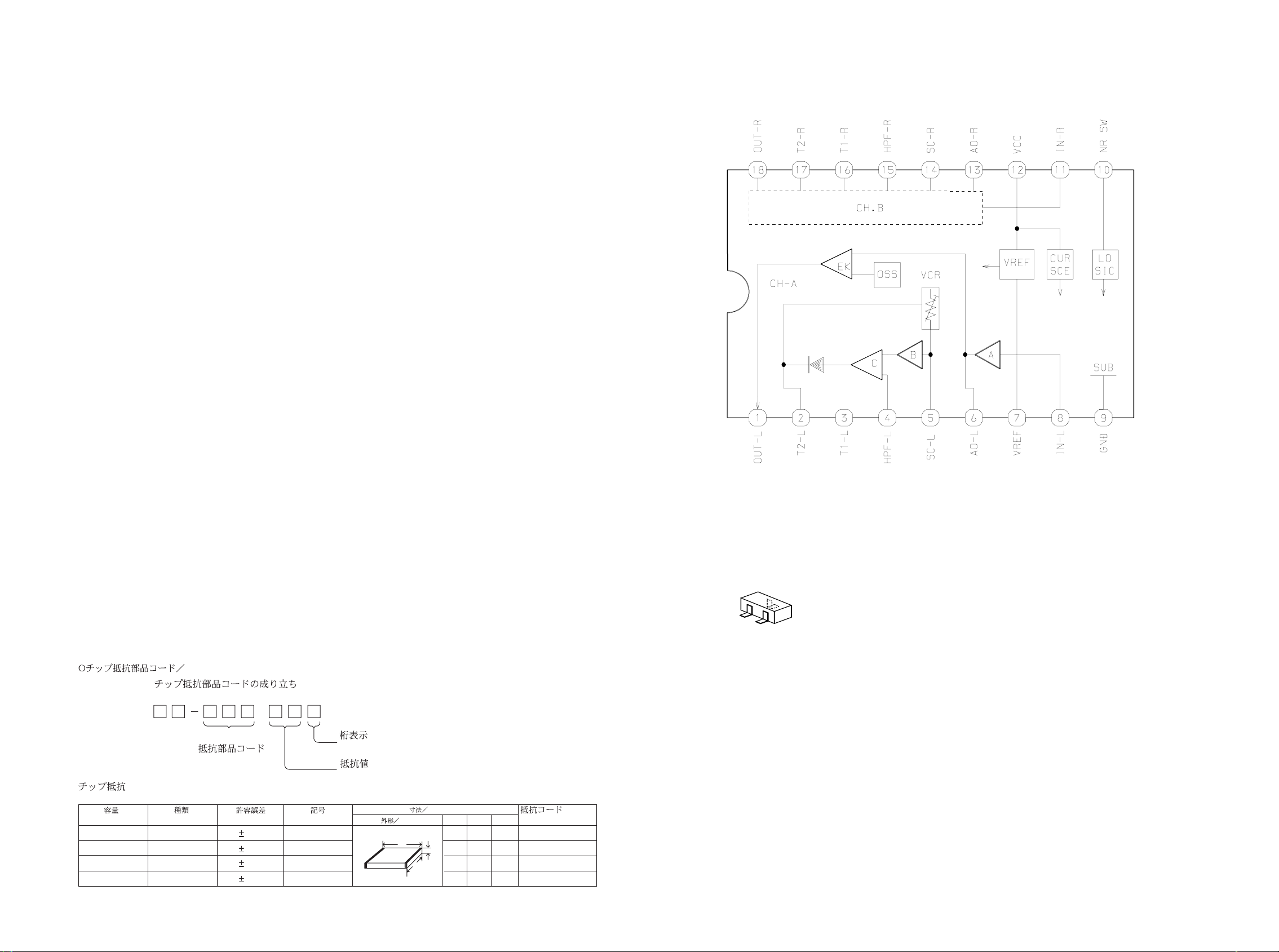
Resistor Code
Chip Resistor Part Coding
Figure
Value of resistor
Chip resistor
Wattage Type Tolerance
1/16W
1/10W
1/8W
1608
2125
3216
5%
5%
5%
CJ
CJ
CJ
Form LW t
1.6 0.8 0.45
2 1.25 0.45
3.2 1.6
108
118
128
: A
: A
CHIP RESISTOR PART CODE
0.55
Resistor Code
Dimensions (mm)
Symbol
1/16W 1005 5% CJ
1.0 0.5 0.35 104
Lt
W
IC BLOCK DIAGRAM
43
IC,AN7375NS
2SC2712
RN1411
TRANSISTOR ILLUSTRATION
BE
C